

KitchenAid KAC-48 Technical Education

TECHNICAL EDUCATION
JOB AID 4317414
KAC-48
MICROWAVE OVEN /
HOOD COMBINATION
MODEL: KHMS1850S

FORWARD
This KitchenAid Job Aid, “Microwave Oven / Hood Combination” (Part No. 4317414) provides
the In-Home Service Professional with information on the installation, operation, and service of
the Microwave Hood Combination. For specific information on the model being serviced, refer
to the Use and Care Guide or Tech Sheet provided with the Microwave Oven / Hood Combination.
The Wiring Diagram and Strip Circuits used in this Job Aid are typical and should be used for
training purposes only. Always use the Wiring Diagram supplied with the product when servicing
the unit.
GOALS AND OBJECTIVES
The goal of this Job Aid is to provide information that will enable the In-Home Service Professional to properly diagnose malfunctions and repair the KitchenAid Microwave Oven / Hood
Combination.
The objectives of this Job Aid are to:
•
Understand and follow proper safety precautions.
•
Successfully troubleshoot and diagnose malfunctions.
•
Successfully perform necessary repairs.
•
Successfully return the microwave oven to its proper operational status.
WHIRLPOOL CORPORATION assumes no responsibility for any repairs made on
our products by anyone other than authorized In-Home Service Professionals.
Copyright © 2007, Whirlpool Corporation, Benton Harbor, MI 49022
- ii -

TABLE OF CONTENTS
Page
GENERAL . . . . . . . . . . . . . . . . . . . . . . . . . . . . . . . . . . . . . . . . . . . . . . . . . . . . . . . . . . . . . . 1-1
Microwave Oven Safety. . . . . . . . . . . . . . . . . . . . . . . . . . . . . . . . . . . . . . . . . . . . . . . . . . . 1-1
Precautions to Be Observed Before and During Servicing to Avoid
Possible Exposure to Excessive Microwave Energy . . . . . . . . . . . . . . . . . . . . . . . . . . . 1-2
Model and Serial Number Designations . . . . . . . . . . . . . . . . . . . . . . . . . . . . . . . . . . . . . . 1-3
Model and Serial Number Label and Tech Sheet Locations . . . . . . . . . . . . . . . . . . . . . . . 1-4
Specifications . . . . . . . . . . . . . . . . . . . . . . . . . . . . . . . . . . . . . . . . . . . . . . . . . . . . . . . . . . 1-5
INSTALLATION INFORMATION . . . . . . . . . . . . . . . . . . . . . . . . . . . . . . . . . . . . . . . . . . . . . 2-1
Installation Requirements . . . . . . . . . . . . . . . . . . . . . . . . . . . . . . . . . . . . . . . . . . . . . . . . . 2-1
Installation Instructions . . . . . . . . . . . . . . . . . . . . . . . . . . . . . . . . . . . . . . . . . . . . . . . . . . . 2-3
PRODUCT OPERATION . . . . . . . . . . . . . . . . . . . . . . . . . . . . . . . . . . . . . . . . . . . . . . . . . . . . 3-1
Parts and Features . . . . . . . . . . . . . . . . . . . . . . . . . . . . . . . . . . . . . . . . . . . . . . . . . . . . . . 3-1
Microwave Oven Control . . . . . . . . . . . . . . . . . . . . . . . . . . . . . . . . . . . . . . . . . . . . . . . . . . 3-2
COMPONENT ACCESS . . . . . . . . . . . . . . . . . . . . . . . . . . . . . . . . . . . . . . . . . . . . . . . . . . 4-1
Component Locations . . . . . . . . . . . . . . . . . . . . . . . . . . . . . . . . . . . . . . . . . . . . . . . . . . . . 4-1
Removing a Hood Lamp Socket and Bottom Cover . . . . . . . . . . . . . . . . . . . . . . . . . . . . . 4-2
Removing the Cabinet . . . . . . . . . . . . . . . . . . . . . . . . . . . . . . . . . . . . . . . . . . . . . . . . . . . . 4-4
Removing Cavity Thermostat #3 and the Humidity Sensor . . . . . . . . . . . . . . . . . . . . . . . . 4-5
Removing the Hood Exhaust Fan Motor . . . . . . . . . . . . . . . . . . . . . . . . . . . . . . . . . . . . . . 4-8
Removing the Cavity Lamp Holder, the Stirrer Motor
and Cavity Thermostat #2 . . . . . . . . . . . . . . . . . . . . . . . . . . . . . . . . . . . . . . . . . . . . . . . 4-9
Removing Cavity Thermostat #1, the Motor Capacitor,
the AC Line Filter and the Power Supply Cord . . . . . . . . . . . . . . . . . . . . . . . . . . . . . . 4-12
Removing the Electronic Control Board and the Touch Control Assembly . . . . . . . . . . . 4-14
Removing the Primary, Secondary and Monitor Interlock Switches . . . . . . . . . . . . . . . . 4-16
Removing the Line Fuse Holder and the Magnetron Thermostat . . . . . . . . . . . . . . . . . . 4-18
Removing the Cooling Fan Motor and the Exhaust Fan Thermostat . . . . . . . . . . . . . . . 4-19
Removing High-Voltage Diode and the Power Resistor . . . . . . . . . . . . . . . . . . . . . . . . . 4-20
Removing the High-Voltage Capacitor and the Magnetron . . . . . . . . . . . . . . . . . . . . . . . 4-21
Removing the High-Voltage Transformer . . . . . . . . . . . . . . . . . . . . . . . . . . . . . . . . . . . . 4-24
Removing the Turntable Motor . . . . . . . . . . . . . . . . . . . . . . . . . . . . . . . . . . . . . . . . . . . . 4-25
Removing the Oven Door and Components . . . . . . . . . . . . . . . . . . . . . . . . . . . . . . . . . . 4-26
- iii -

Page
COMPONENT TESTING . . . . . . . . . . . . . . . . . . . . . . . . . . . . . . . . . . . . . . . . . . . . . . . . . . . 5-1
Thermostats . . . . . . . . . . . . . . . . . . . . . . . . . . . . . . . . . . . . . . . . . . . . . . . . . . . . . . . . . . . . 5-1
Humidity Sensor . . . . . . . . . . . . . . . . . . . . . . . . . . . . . . . . . . . . . . . . . . . . . . . . . . . . . . . . 5-2
Hood Exhaust Fan Motor. . . . . . . . . . . . . . . . . . . . . . . . . . . . . . . . . . . . . . . . . . . . . . . . . . 5-2
Stirrer Motor . . . . . . . . . . . . . . . . . . . . . . . . . . . . . . . . . . . . . . . . . . . . . . . . . . . . . . . . . . . . 5-3
Motor Capacitor . . . . . . . . . . . . . . . . . . . . . . . . . . . . . . . . . . . . . . . . . . . . . . . . . . . . . . . . . 5-3
AC Line Filter . . . . . . . . . . . . . . . . . . . . . . . . . . . . . . . . . . . . . . . . . . . . . . . . . . . . . . . . . . . 5-4
Door Interlock Switches . . . . . . . . . . . . . . . . . . . . . . . . . . . . . . . . . . . . . . . . . . . . . . . . . . . 5-4
Line Fuse . . . . . . . . . . . . . . . . . . . . . . . . . . . . . . . . . . . . . . . . . . . . . . . . . . . . . . . . . . . . . . 5-5
Cooling Fan Motor . . . . . . . . . . . . . . . . . . . . . . . . . . . . . . . . . . . . . . . . . . . . . . . . . . . . . . . 5-5
High-Voltage Diode . . . . . . . . . . . . . . . . . . . . . . . . . . . . . . . . . . . . . . . . . . . . . . . . . . . . . . 5-6
Power Resistor . . . . . . . . . . . . . . . . . . . . . . . . . . . . . . . . . . . . . . . . . . . . . . . . . . . . . . . . . 5-6
High-Voltage Capacitor . . . . . . . . . . . . . . . . . . . . . . . . . . . . . . . . . . . . . . . . . . . . . . . . . . . 5-7
Magnetron . . . . . . . . . . . . . . . . . . . . . . . . . . . . . . . . . . . . . . . . . . . . . . . . . . . . . . . . . . . . . 5-7
High-Voltage Transformer . . . . . . . . . . . . . . . . . . . . . . . . . . . . . . . . . . . . . . . . . . . . . . . . . 5-8
Turntable Motor . . . . . . . . . . . . . . . . . . . . . . . . . . . . . . . . . . . . . . . . . . . . . . . . . . . . . . . . . 5-8
DIAGNOSTICS AND TROUBLESHOOTING . . . . . . . . . . . . . . . . . . . . . . . . . . . . . . . . . . . 6-1
Primary, Secondary and Monitor Interlock Switch Checkout Procedure . . . . . . . . . . . . . . 6-1
Failure Code Indications . . . . . . . . . . . . . . . . . . . . . . . . . . . . . . . . . . . . . . . . . . . . . . . . . . 6-2
Touch Panel and Electronic Control Test . . . . . . . . . . . . . . . . . . . . . . . . . . . . . . . . . . . . . . 6-3
Microwave Oven Power Output Test . . . . . . . . . . . . . . . . . . . . . . . . . . . . . . . . . . . . . . . . . 6-4
WIRING DIAGRAM AND STRIP CIRCUITS . . . . . . . . . . . . . . . . . . . . . . . . . . . . . . . . . . . . 7-1
Wiring Diagram . . . . . . . . . . . . . . . . . . . . . . . . . . . . . . . . . . . . . . . . . . . . . . . . . . . . . . . . . 7-1
Strip Circuits . . . . . . . . . . . . . . . . . . . . . . . . . . . . . . . . . . . . . . . . . . . . . . . . . . . . . . . . . . . 7-2
- iv -

GENERAL
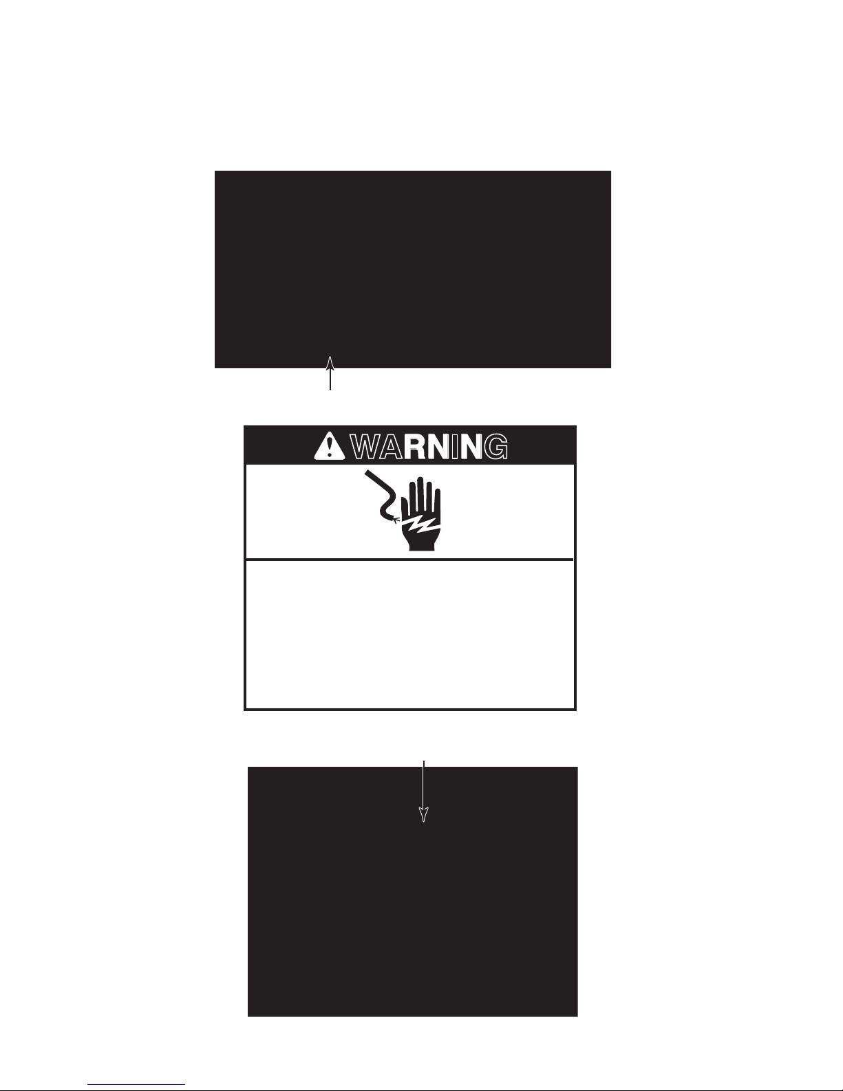
DANGER
WARNING
MICROWAVE OVEN SAFETY
Your safety and the safety of others are very important.
We have provided many important safety messages in this manual and on your appliance.
Always read and obey all safety messages.
This is the safety alert symbol.
This symbol alerts you to potential hazards that can kill or hurt you and others.
All safety messages will follow the safety alert symbol and either the word
“DANGER” or “WARNING.” These words mean:
You can be killed or seriously injured if you don’t
immediately follow instructions.
You can be killed or seriously injured if you don’t
follow instructions.
All safety messages will tell you what the potential hazard is, tell you how to reduce the chance
of injury, and tell you what can happen if the instructions are not followed.
1-1

PRECAUTIONS TO BE OBSERVED BEFORE AND
DURING SERVICING TO AVOID POSSIBLE EXPOSURE
TO EXCESSIVE MICROWAVE ENERGY
a) Do not operate or allow the oven to be operated with the door open.
b) Make the following safety checks on all ovens to be serviced before activating the
magnetron or other microwave source, and make repairs as necessary:
1. Interlock Operation
2. Proper Door Closing
3. Seal and Sealing Surfaces (Arcing, Wear and Other Damage)
4. Damage to or Loosening of Hinges and Latches
5. Evidence of Dropping or Abuse
Before turning on microwave power for any service test or inspection within the microwave
c)
generating compartments, check the magnetron, waveguide or transmission line, and
cavity for proper alignment, integrity and connections.
d)
Any defective or misadjusted components in the interlock, monitor, door seal, and micro-
wave generation and transmission systems shall be repaired, replaced, or adjusted by
procedures described in service manual before the oven is released to the owner.
A microwave leakage check to verify compliance with the Federal Performance Standard
e)
should be performed on each oven prior to release to the owner.
Do not attempt to operate the oven if the door glass is broken.
f)
1-2

MODEL AND SERIAL NUMBER DESIGNATIONS
MODEL NUMBER
MODEL NUMBER K HM S 18 5 0 S BL 0
PRODUCT GROUP
K = KITCHENAID BRAND
PRODUCT IDENTIFICATION
BH = BUILT-IN HIGH SPEED OVEN
BM = BUILT-IN MICROWAVE
CM = COUNTERTOP MICROWAVE
HM = MICROWAVE HOOD
HS = HIGH SPEED
MERCHANDISING SCHEME
S = SENSOR
C = MICRO-CONVECTION
CAPACITY / SIZE / SERIES / CONFIGURATION
05 = 0.5 CU FT 16 = 1.6 CU FT
08 = 0.8 CU FT 17 = 1.7 CU FT
10 = 1.0 CU FT 18 = 1.8 CU FT
13 = 1.3 CU FT 20 = 2.0 CU FT
14 = 1.4 CU FT 22 = 2.2 CU FT
15 = 1.5 CU FT
FEATURES
2 = PLUS FEATURES
5 = DELUXE FEATURES
6 = MICRO-CONVECTION
7 = MICRO-CONVECTION WITH SENSOR
9 = MULTIMODE - HI SPEED - CONVECTION
S = CARRY-IN WARRANTY (EFFECTIVE 02/96)
X = IN-HOME WARRANTY (EFFECTIVE 02/96)
PRODUCT SIZE
0 = 30˝ WIDE 7 = 27˝ WIDE
2 = 22˝ WIDE 8 = 18˝ WIDE
4 = 24˝ WIDE 9 = 19˝ WIDE
6 = 36˝ WIDE
YEAR OF INTRODUCTION
S = 2007
COLOR CODE
WH = WHITE, BL = BLACK, SS = STAINLESS STEEL
ENGINEERING CHANGE (0, 1, 2, ETC.)
SERIAL NUMBER
SERIAL NUMBER TR T 44 10023
MANUFACTURING SITE
TR = SHUNDE, CHINA
YEAR OF PRODUCTION
T = 2007
WEEK OF PRODUCTION
44TH WEEK
PRODUCT SEQUENCE NUMBER
1-3
MODEL AND SERIAL NUMBER LABEL AND
WARNING
TECH SHEET LOCATIONS
The Model/Serial Number label and Tech Sheet locations are shown below.
Model/Serial Number Label
Disconnect power before servicing.
Replace all parts and panels before
operating.
Failure to do so can result in death or
electrical shock.
Electrical Shock Hazard
Tech Sheet Location
1-4

SPECIFICATIONS
Model KHMS1850SBL/WH/SS
Control System
Timer Electronic
Limits 99 min. 99 sec.
Scale Linear (Digital)
Operation Touch Control, Pads TBD
Display 5 + 2 Digit - Blue-Green
Clock Yes
Independent Minute Timer Yes
Stage Cooking Yes (3)
In-Use Reprogramming Yes
More/Less Function Yes - Hidden “Cook Power” Button
Keypad Disable/Control Lockout Mode Yes - Press “OFF/Cancel” Key For 5 Seconds
Cook Power Yes (10 Levels)
Exhaust Fan Yes - 1-Key Operation
Number of Speeds 5 (including Off)
Manual Off Yes
Automatic Turn-On @
Cooktop Light Halogen
Settings 3 Levels (High, Night, Off)
Stoppable Turntable Function / Button Yes
Oven Interior Features
Size (Inches)
Size (Metric) 581 mm W x 241 mm H x 368 mm D
Capacity 1.8 Cu. Ft.
Finish Powder Coating
Cooking Power 1000 Watts
Glass Turntable Diameter
Ventilation Standard Air Flow System
Cooling Fan Automatic: On if Oven Is Operating; Off If Door Is Open
Door Features
Side Swing Left-Hand (Hinge Side)
Seals Two-Stage
Microwave System
Distribution Top Feed w/ Stirrer
Magnetron Standard Transformer
Safety Features
Interlock 3 Door/Latch Operated Primary, Secondary and Monitor
Thermal Protectors 5 - 1 Magnetron, 1 Oven Cavity, 1 Hood, 2 Wave Guide
140°F/60°C
22 7/8˝ W x 9 1/2˝ H x 14 1/2˝ D
12˝
1-5

Ventilation System
Type Convertible Recirculation or Exhaust Vertical/Horizontal
Recirculation CFM Out 162
Exhaust CFM Out 200
Touch Control 4-Speed
Auto On/High Speed
Damper Yes
Grease Filter Yes (2)
Charcoal Filter Yes - Behind Mesh Filter Under Unit
Blower Type Twin Squirrel Cage
Shipped Recirculation Mode
Exterior Features
Outside Dimensions (Inches)
Outside Dimensions (Metric) 762 mm x 457 mm x 438 mm
Power Cord Length 3 Feet
Other Specications
Electrical
Domestic Use Only Yes
Agency Approvals FCC, DHHS, CDRH, UL
Net Weight (Approx.) 73 Lbs.
Literature
Use & Care Guide #8206647
Cooking Guide (Label) #8206649
Installation Instructions #8206650
Warranty 1 Year Full; 2-5 Year Limited, Magnetron Tube
Tech Sheet #8206648
Job Aid #4317414
Yes: 140°F / 60°C
30˝ x 18˝ x 17 1/4˝
120 VAC, Single Phase, 60 Hz
1500 Watts, For Use With 15-20 Amp Circuit
1-6
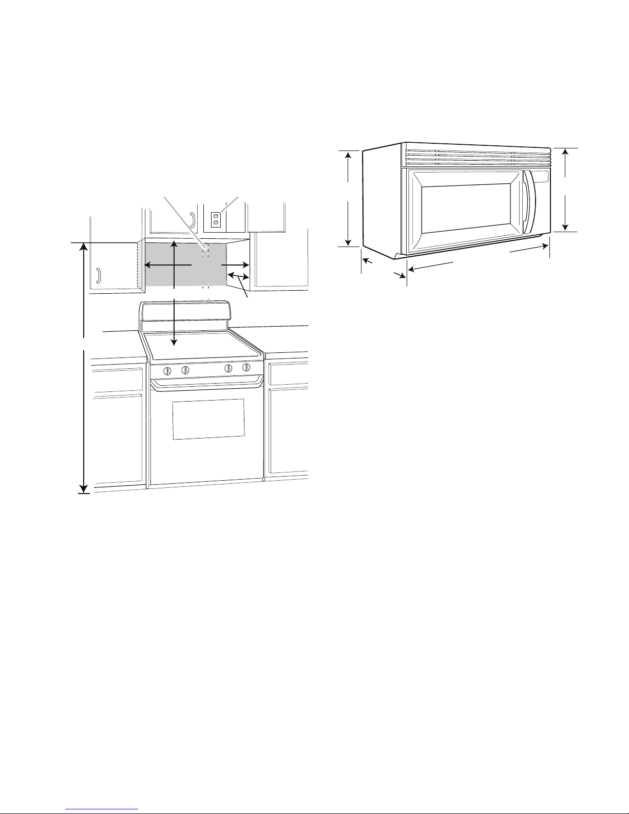
INSTALLATION INFORMATION
*30" (76.2 cm) is typical for 66" (167.6 cm) installation height.
Exact dimensions may vary depending on type of range/
cooktop below.
A. 2" x 4" wall stud
B. Grounded 3 prong outlet
66" (167.6 cm) min.
12" (30.5 cm) min.
14" (35.6 cm) max.
A B
30" (76.2 cm) typical*
30"
(76.2 cm)
min.
mc 0.67( )
)m 4.93( c
17-1/4
"
29-7/8
"
(43.8 cm)
"
(42.0 cm)
"
15-1/2
16-1/2
INSTALLATION REQUIREMENTS
INSTALLATION DIMENSIONS
NOTE: The grounded 3 prong outlet must be
inside the upper cabinet. See “Electrical Requirements,” page 2-2.
PRODUCT DIMENSIONS
2-1

WARNING
ELECTRICAL REQUIREMENTS
Electrical Shock Hazard
Plug into a grounded 3 prong outlet.
Do not remove ground prong.
Do not use an adapter.
Do not use an extension cord.
Failure to follow these instructions can
result in death, fire, or electrical shock.
Observe all governing codes and ordinances.
Required:
A 120 Volt, 60 Hz, AC only, 15- or 20-amp
•
fused electrical supply (or circuit breaker).
Recommended:
GROUNDING INSTRUCTIONS
For all cord connected appliances:
•
The microwave oven must be grounded.
In the event of an electrical short circuit,
grounding reduces the risk of electric
shock by providing an escape wire for
the electric current. The microwave oven
is equipped with a cord having a grounding wire with a grounding plug. The plug
must be plugged into an outlet that is
properly installed and grounded.
WARNING: Improper use of the ground-
ing plug can result in a risk of electric
shock. Consult a qualified electrician
or serviceman if the grounding instructions are not completely understood, or
if doubt exists as to whether the microwave oven is properly grounded.
Do
not use an extension cord. If the
power supply cord is too short, have a
qualified electrician or serviceman install
an outlet near the microwave oven.
•
A time-delay fuse or circuit breaker is
recommended.
•
A separate circuit serving only this microwave oven.
2-2

INSTALLATION INSTRUCTIONS
A Screw
B. Damper plate
A
B
A. Screws
A
A. Blower motor
A
A
A. Exhaust port
A. Damper plate
B. Tabs at back of damper plate
C. Slots in back of microwave oven exterio
r
D. Damper plate tabs
E. Slots in top of microwave oven exterior
A B C D E
ROTATE BLOWER MOTOR
The microwave oven is set for recirculation
installation. For wall or roof venting, changes
must be made to the venting system.
NOTE: Skip this section if you are using recirculation installation. Keep the damper assembly in case the venting method is changed, or
the microwave oven is reinstalled in another
location where wall or roof venting may be
used.
Wall Venting Installation Only
Remove screw attaching damper plate
1.
to top of microwave oven exterior. Slide
damper plate back and lift up.
5. Rotate blower motor end over end.
6. Rotate blower motor so that exhaust
ports face the back of microwave oven,
and lower blower motor back into the
microwave oven.
2. Keep damper plate and screw together
and set aside.
Remove two screws attaching blower
3.
motor to back of microwave oven.
4. Lift blower motor out of microwave oven.
Reattach blower motor to back of
7.
microwave oven with 2 screws removed
in Step 3.
Reattach damper plate. Make sure tabs
8.
at top and back of damper plate are inserted fully into their respective slots in
the microwave oven.
9. Secure damper plate with screw.
2-3

A. Exhaust port
A
Roof Venting Installation Only
A. Damper plate
B. Tabs at back of damper plate
C. Slots in back of microwave oven exterio
r
D. Damper plate tabs
E. Slots in top of microwave oven exterior
A B C D E
WARNING
1. Repeat Step 1 from “Wall Venting Installation Only on page 13.”
Repeat Step 2 from “Wall Venting Instal-
2.
lation Only.”
Repeat Step 3 from “Wall Venting Instal-
3.
lation Only.”
Repeat Step 4 from “Wall Venting Instal-
4.
lation Only.”
Rotate the blower motor so the exhaust
5.
ports face the top of the microwave oven
and the flat sides of the blower motor
face the back of the microwave oven.
Lower the blower motor back into the
microwave oven.
7. Reattach damper plate. Make sure tabs
at top and back of damper plate are inserted fully into their respective slots in
the microwave oven.
8. Secure damper plate with screw.
INSTALL THE MICROWAVE OVEN
IMPORTANT: If blower motor is not posi-
tioned with flat sides facing the back of the
microwave oven (as shown), performance will
be poor.
Reattach blower motor to back of mi-
6.
crowave oven with 2 screws removed in
Step 3 of “Wall Venting Installation Only.”
Securely tighten screws.
NOTE: If blower motor is not correctly oriented, the 2 screws removed in Step 3 cannot be
reattached to the microwave oven.
Excessive Weight Hazard
Use two or more people to move and
install microwave oven.
Failure to do so can result in back or
other injury.
IMPORTANT: The control side of the
microwave oven is the heavy side. Handle the
microwave oven gently.
Place a washer on each 1/4-20 x 3˝ bolt
1.
and place inside upper cabinet near the
3/8˝ (10 mm) holes.
Make sure the microwave oven door is
2.
closed and taped shut.
2-4

3. Using 2 or more people, lift microwave
A. Mounting plate
B. Support tabs
A
B
A. Bolts
A
oven and hang it on support tabs at the
bottom of mounting plate.
NOTE: To avoid damage to the microwave
oven, do not grip or use the door or door
handle while the microwave oven is being
handled.
5. Rotate the microwave oven up toward
upper cabinet.
NOTE: If venting through the wall, make sure
the damper assembly fits easily into the vent
in the wall cutout.
Push the microwave oven against mount-
6.
ing plate and hold in place.
NOTE: If microwave oven does not need to
be adjusted, skip steps 7-9.
If adjustment is required, rotate the
7.
microwave oven downward. Using 2 or
more people, lift microwave oven off of
mounting plate, and set aside on a protected surface.
Loosen mounting plate screws. Adjust
8.
mounting plate and retighten screws.
9.
Repeat steps 3-6.
10. With the microwave oven centered, and
with at least one person holding it in
place, insert bolts through upper cabinet
into microwave oven. Tighten bolts until
there is no gap between upper cabinet
and microwave oven.
NOTES:
•
With front of microwave oven still tilted,
4.
thread power supply cord through the
power supply cord hole in the bottom of
the upper cabinet.
Some upper cabinets may require bolts
longer or shorter than 3˝ (7.6 cm). Longer
or shorter bolts are available at most hardware stores.
•
Overtightening bolts may warp the top
of the microwave oven. To avoid warping, wood filler blocks may be added. The
blocks must be the same thickness as the
space between the upper cabinet bottom
and the microwave oven.
2-5

For Roof Venting Installation Only
A. Raised tabs
B. Damper assembly
C. Sheet metal screw
D. Upper cabinet cutout
E. Long tab
F. Damper plate
A B C
D E F
A. Vent
B. Damper assembly (under vent)
A B
A. Filler panels
A
1. Insert damper assembly through the
cabinet cutout so that the long tab of the
damper assembly slides under the raised
tabs of the damper plate. Then secure
with sheet metal screw.
NOTE: The screw cannot be installed if the
damper assembly is not positioned as shown.
2. Connect vent to damper assembly.
ACCESSORIES
Filler Panel Kits are available from your
dealer to use when installing this microwave
oven in a 36˝ (91.4 cm) or 42˝ (106.7 cm) wide
opening. The filler panels come in pairs. Each
panel is 3˝ (7.6 cm) wide.
Filler Panel Kit Number 8171336 White
8171337 Black
8171338 Biscuit
8171339 Stainless Steel
99403 Almond
See your authorized dealer or service center
for details.
2-6
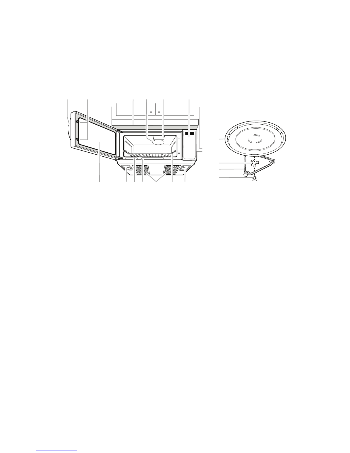
PRODUCT OPERATION
A. Door handle
B. Door lock system
C. Vent grille
D. Microwave inlet cover
E. Microwave oven light
F. Control panel
G. Metal shielded window
H. Cooktop lights
I. Model and serial number plate
J. Cooking guide label
K. Charcoal and Grease filters
(shipped in microwave oven
cavity)
L. Cooking rack
A B C D E F
G H I J K L H
A. Turntable
B. Hub
C. Support
D. Shaft
A
B
C
D
PARTS AND FEATURES
This manual may cover several different models. The model you have purchased may have
some or all of the features shown here.
The appearance of your particular model
may differ slightly from the illustrations in this
manual.
3-1

MICROWAVE OVEN CONTROL
1
2
3
SENSOR
ENTER
AUTO
COOK
REHEAT
TIMER
DEFROST
WARM
QTY TURN
TABLE
OFF
LBS OZ
POWER
START?
When the microwave oven is in use, the display shows cooking power, quantities, weights
and/or prompts. When the microwave oven is
not in use, the display shows the time of day
or Timer countdown.
START
The START control starts any function. If nonsensor cooking is interrupted, touching START
will resume the preset cycle.
Add a Minute
The Add a Minute control automatically starts
the microwave oven at 100% power for 1
minute, and adds 1 minute of cook time up to
10 minutes, with each additional touch of the
control.
Touching Add a Minute during a cook cycle
will add 1 minute of cook time at the current
cook power.
OFF
The OFF control (Cancel OFF) clears any incorrect command and cancels all functions except
for the Demo Mode. It will not erase the time
of day. The control panel can be locked and
unlocked using the OFF control (see “Control
Lock” section).
DISPLAY
When power is rst supplied to the microwave
oven, a “:” will blink in the display. Touch OFF
(Cancel OFF) to stop the blinking. If the “:”
blinks in the display at any other time, a power
failure has occurred. Touch OFF and reset the
clock if needed.
If “RETRY” blinks in the display for 1 second,
an invalid value has been entered. Retry your
entry.
The microwave oven will also turn off when
the door is opened. Close the door and touch
START to resume the cycle. A sensor cooking
cycle may not be resumed if interrupted by
opening the door.
Clock
This is a standard 12-hour clock (12:0011:59) and does not show a.m. or p.m.
To Set:
The microwave oven and timer must be off.
Touch Clock.
1.
2. Touch the number pads to set the time of
day.
3. Touch Clock or START.
3-2

To Remove:
To Set:
1. Touch Clock.
2. Touch 0.
3. Touch Clock.
The time will disappear, and “:” will appear on
the display.
TONES
Tones are audible signals, indicating the
following:
One tone
•
Valid entry (short tone)
•
End-of-Timer countdown (long tone)
Two tones
•
Reminder, repeating each minute after the
end-of-cycle tones
•
End of stage in multistage cooking
•
Hidden feature has been entered or exited
Three tones
•
Invalid entry
Four tones
1. Touch Timer.
If no action is taken after 1 minute, the dis-
play will return to the time-of-day mode.
2. Touch the number pads to set the length
of time.
Touch Timer or START.
3.
If Timer or START is not touched within
5 seconds, “START?” will appear in the
display. If Timer or START is not touched
within one minute, the display will return to
the time-of-day mode and the programmed
function will be canceled.
When
the set time ends, “END” will appear
in the display and one tone will sound.
T
ouching OFF while a cook function is
active in the display will cancel the cook
function, not the Timer.
To cancel the Timer, touch TIMER or OFF while
the countdown is active in the display.
The length of time can be changed during the
countdown by repeating the above steps.
End of cycle
•
To Turn Off Valid Entry Tones: Touch and
hold the number pad “1” for 5 seconds until two
tones sound. Repeat to turn tones back on.
To Turn Off All Tones (except End-of-Timer
and hidden feature signals): Touch and hold
the number pad “2” for 5 seconds until two
tones sound. Repeat to turn tones back on.
TIMER
The Timer can be set in minutes and seconds,
up to 99 minutes 99 seconds, and counts down
the set time.
NOTE: The Timer does not start or stop the
microwave oven.
When the Timer is in use, the microwave oven
can also operate. To see the countdown for 5
seconds when the microwave oven is in use,
touch Timer.
CONTROL LOCK
The Control Lock shuts down the control panel
pads to avoid unintended use of the microwave
oven. When the control is locked, only the Vent
Fan and Light pads will function.
To Lock/Unlock Control: The microwave
oven and Timer must be off. Touch and hold
OFF for 5 seconds until two tones sound and a
lock icon appears in the display. Repeat to unlock and remove the lock icon from display.
VENT FAN
The vent fan has 4 speeds: high, medium-high,
medium and low.
To protect the microwave oven, if the temperature from the range or cooktop below the
microwave oven gets too hot, the vent fan will
automatically turn on at high speed. It may
stay on for up to 1 hour to cool the microwave
oven. When this occurs, the vent fan cannot
be turned off.
3-3

To Turn Vent Fan On/Off: Repeatedly touch
the Vent Fan 4 Speeds pad to cycle through
the four speeds, and then turn the fan off.
COOKTOP LIGHT
The cooktop light has three settings: on, night
and off.
To Turn On/Night/Off: Touch Light On/
Night/Off pad repeatedly to cycle through the
settings.
DEMO MODE
The Demo Mode is ideal for learning how to
use the microwave oven. When set, functions
can be entered without actually turning on the
magnetron. The microwave oven light will come
on, the fan will run, and if on, the turntable will
rotate.
To Turn On/Off: The microwave oven and
Timer must be off. Touch and hold Timer for 5
seconds until two tones sound and “d” appears
in the display. Repeat to turn off and remove
“d” from the display.
3-4

COMPONENT ACCESS
A. Cavity Thermostat #3—opens @ 329ºF
(165ºC), closes at –31ºF (–35ºC)
B. Humidity Sensor
C. Hood Exhaust Fan Motor
D. Cavity Thermostat #2—opens at 257ºF
(125ºC), closes at –31ºF (–35ºC)
E. Cavity Thermostat #1—opens @ 257ºF
(125ºC), closes @ –31ºF (–35ºC)
F. AC Line Filter
G. Power Resistor
H. Magnetron
I. Magnetron Thermostat—opens @
257ºF (125ºC), closes @ 185ºF (85ºC)
J. Cooling Fan Motor
K. H.V. Transformer
L. H.V. Capacitor
M. H.V. Diode
N. Line Fuse (20 amp)
O. Hood (cooktop) Lamp Holders
P. Hood (cooktop) Lamps
Q. Fuse Holder
R. Electronic Control
S. Touch Panel
T. Exhaust Fan Thermostat—opens @
113ºF (45ºC), closes @ 140ºF (60ºC)
U. Secondary Interlock Switch
V. Monitor Interlock Switch
W. Primary Interlock Switch
X. Turntable Motor
Y. Cavity Lamp Holder
Z. Cavity Lamp
AA. Motor Capacitor
BB. Stirrer Motor
X
T
W
V
P
AA
M
K
N
Q
S
Z
U
J
I
G
D
H
E
F
B
L
ACS
E
5:4
L
BB
O
P
Y
A
C
O
R
This section instructs you on how to service each component inside the Microwave Oven/Hood
Combination. The components and their locations are shown below.
COMPONENT LOCATIONS
4-1
 Loading...