

Page 1
TECHNICAL EDUCATION
ELECTRIC BUILT-IN
SINGLE OVEN
KAC-28
JOB AID 4317323
Page 2

FORWARD
This Job Aid, “KitchenAid Electric Built-In Single Oven,” (Part No. 4317323), provides the
technician with information on the installation, operation, and service of the Electric Built-In Single
Oven. It is to be used as a training Job Aid and Service Manual. For specific information on the
model being serviced, refer to the “Use and Care Guide,” or “Tech Sheet” provided with the oven.
The Wiring Diagrams and Strip Circuits used in this Job Aid are typical and should be used for
training purposes only. Always use the Wiring Diagram supplied with the product when servicing
the unit.
GOALS AND OBJECTIVES
The goal of this Job Aid is to provide detailed information that will enable the service technician to
properly diagnose malfunctions and repair the KitchenAid Electric Built-In Single Oven.
The objectives of this Job Aid are to:
• Understand and follow proper safety precautions.
• Successfully troubleshoot and diagnose malfunctions.
• Successfully perform necessary repairs.
• Successfully return the oven to its proper operational status.
WHIRLPOOL CORPORATION assumes no responsibility for any repairs made
on our products by anyone other than Authorized Service Technicians.
Copyright © 2001, Whirlpool Corporation, Benton Harbor, MI 49022
- ii -
Page 3

TABLE OF CONTENTS
Page
GENERAL............................................................................................................................... 1-1
Important Safety Information ............................................................................................. 1-1
KitchenAid Model & Serial Number Designations.............................................................. 1-2
Model & Serial Number Label And Tech Sheet Locations................................................. 1-3
Specifications..................................................................................................................... 1-4
KitchenAid Single Thermal Convection Oven Warranty .................................................... 1-7
KitchenAid Electric Built-In Oven Warranty ....................................................................... 1-8
INSTALLATION INFORMATION ........................................................................................... 2-1
Electrical Supply Requirements ......................................................................................... 2-1
Removing & Reinstalling The Oven Door .......................................................................... 2-3
Oven/Cooktop Combination-Approved Installation ............................................................ 2-4
THEORY OF OPERATION ..................................................................................................... 2-1
Air Flow .............................................................................................................................. 3-1
The Oven Shutdown Thermal Fuse ................................................................................... 3-2
The Oven Door Latch Assembly ........................................................................................ 3-3
How The Self-Clean Cycle Works ..................................................................................... 3-4
COMPONENT ACCESS ......................................................................................................... 4-1
Component Locations ........................................................................................................ 4-1
Removing The Oven Control/Display Boards And The Touch Panel Assembly................ 4-2
Removing The Power Supply Wiring Terminal Block And The Blower Motor ................... 4-4
Removing The Oven Light Transformer & The Control Power Transformer ..................... 4-6
Removing The Oven Door Latch Assembly....................................................................... 4-7
Removing An Oven Halogen Light And The Oven Temperature Sensor .......................... 4-8
Removing The Broil Element ........................................................................................... 4-10
Removing The Meat Probe Jack ..................................................................................... 4-11
Removing The Hidden Bake Element.............................................................................. 4-12
Removing The Convection Bake Element And The Fan Motor Assembly ...................... 4-14
Removing The Oven Shutdown Thermal Fuse................................................................ 4-16
Removing The Oven Door Glass, Hinges, & Handle ....................................................... 4-17
Removing The Oven Door Gasket................................................................................... 4-19
COMPONENT TESTING ........................................................................................................ 5-1
Blower Motor...................................................................................................................... 5-1
Oven Temperature Sensor ................................................................................................ 5-1
Convection Bake Element ................................................................................................. 5-2
Convection Fan Motor ....................................................................................................... 5-2
Broil Element ..................................................................................................................... 5-3
Bake Element .................................................................................................................... 5-3
Oven Door Latch Assembly ............................................................................................... 5-4
Oven Shutdown Thermal Fuse .......................................................................................... 5-4
Oven Light & Control Power Transformers ........................................................................ 5-5
- iii -
Page 4

Page
DIAGNOSIS & TROUBLESHOOTING ................................................................................... 6-1
Diagnostics ........................................................................................................................ 6-1
Fahrenheit To Celsius Conversion .................................................................................... 6-1
Programming The Cavity Size ........................................................................................... 6-1
Electrostatic Discharge Sensitive Electronics .................................................................... 6-1
Failure/Error Display Codes............................................................................................... 6-2
Control Panel Test Locations............................................................................................. 6-3
Relay Logic Chart .............................................................................................................. 6-3
WIRING DIAGRAMS & STRIP CIRCUITS ............................................................................. 7-1
Model Number/Tech Sheet Use ........................................................................................ 7-1
Schematic Diagram ........................................................................................................... 7-2
Strip Circuits ...................................................................................................................... 7-3
- iv -
Page 5
GENERAL
IMPORTANT SAFETY INFORMATION
Your safety and the safety of others is very important.
Important safety messages have been provided in this Job Aid. Always read and obey all
safety messages.
This is the safety alert symbol.
This symbol alerts you to hazards that can kill or hurt you
and others.
All safety messages will be preceded by the
safety alert symbol and the word “WARNING.”
All safety messages will identify the hazard, tell
you how to reduce the chance of injury, and tell
you what can happen if the instructions are not
followed.
WARNING
ELECTRICAL SHOCK HAZARD
Disconnect power before servicing.
Replace all panels before operating.
Failure to do so could result in death or
electrical shock.
ELECTROSTATIC DISCHARGE
(ESD) SENSITIVE ELECTRONICS
ESD problems are present everywhere. ESD
may damage or weaken the electronic control
assembly. The new control assembly may appear to work well after repair is finished, but
failure may occur at a later date due to ESD
stress.
• Use an antistatic wrist strap. Connect the
wrist strap to a green ground connection
point or unpainted metal in the appliance;
or touch your finger repeatedly to a green
ground connection point or unpainted metal
in the appliance.
• Before removing the part from its package, touch the antistatic bag to a green
ground connection point or unpainted metal
in the appliance.
• Avoid touching electronic parts or terminal
contacts. Handle the electronic control
assembly by the edges only.
• When repackaging the failed electronic
control assembly in an antistatic bag, observe the above instructions.
1-1
Page 6
KITCHENAID MODEL & SERIAL NUMBER DESIGNATIONS
MODEL NUMBER
MODEL NUMBER K EB S 10 7 D S S 8
INTERNATIONAL SALES IND.
OR MARKETING CHANNEL
IF PRESENT
PRODUCT GROUP
K = KITCHENAID BRAND
PRODUCT IDENTIFICATION
EB = ELECTRIC BUILT-IN OVEN
EH = ELECTRIC BUILT-IN HI SPEED COMBO
EM = ELECTRIC BUILT-IN MICRO COMBO
EW = ELECTRIC WARMING OVEN
GB = GAS BUILT-IN OVEN
GM = GAS BUILT-IN MICRO COMBO OVEN
MERCHANDISING SCHEME
C = FLUSH LOOK
D = DRAWER
I = IMPERIAL
N = INTERNATIONAL COLLECTION EUROPEAN
S = SUPERBA
CAPACITY / SIZE / SERIES / CONFIGURATION
1ST POSITION 2ND POSITION
1 = SINGLE OVEN 4 = 24˝ WIDE
2 = DOUBLE OVEN 6 = 36˝ WIDE
3 = COMBO OVEN 7 = 27˝ WIDE
4 = OVEN W/DRAWER 0 = 30˝ WIDE
5 = MINI OVEN
6 = COMBO W/MINI OVEN
FEATURES
0 = STANDARD FEATURES
1 = STANDARD FEATURES / ELECTRIC CLOCK
5 = DELUXE FEATURES
6 = DELUXE FEATURES / ELECTRIC CLOCK
7 = DELUXE FEATURES / THERMAL CONVECTION
8 = DOUBLE THERMAL CONVECTION
9 = MULTIMODE
YEAR OF INTRODUCTION
D = 1995, G = 1998, H = 1999, J = 2000
COLOR CODE
AL = ALMOND, BL = BLACK, BT = BISCUIT,
WH = WHITE, SS = BRUSHED STAINLESS STEEL
ENGINEERING CHANGE (0, 1, 2, ETC.)
SERIAL NUMBER
SERIAL NUMBER X K 0 3 01006
MANUFACTURING SITE
X = OXFORD
YEAR OF PRODUCTION
K = 2000, L = 2001, M = 2002
WEEK OF PRODUCTION
3RD WEEK
PRODUCT SEQUENCE NUMBER
1-2
Page 7
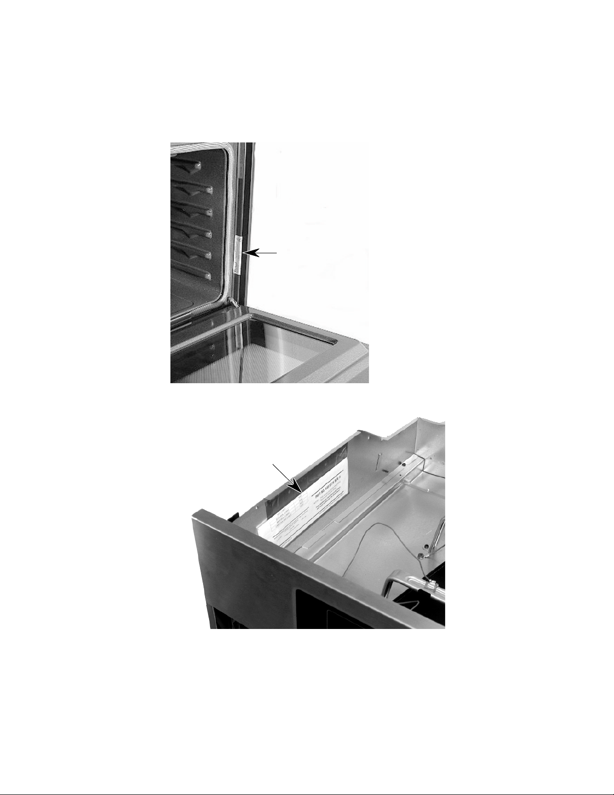
MODEL & SERIAL NUMBER LABEL
AND TECH SHEET LOCATIONS
The Model/Serial Number label and Tech Sheet locations are shown below.
Model & Serial Number Location
Tech Sheet Location
(Below Top Front Cover)
1-3
Page 8
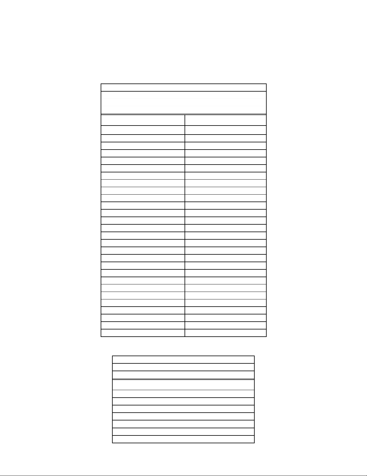
SPECIFICATIONS
Model Number
Colors Available
Model Description
Size-Configuration
Dimensions/Specifications
Overall Height (in)
Overall Width (in)
Overall Depth Inc Hrdwr/Hndl (in)
Depth W/O Handle (in)
Cutout Dimensions
Cutout Height (in) (Measure Or Min/Max)
Cutout Width (in) (Measure Or Min/Max)
Cutout Depth (in) (Measure Or Min/Max)
Other Dimensions
Conduit Size (in) (Length/Diameter)
Net Weight (lbs)
Shipping Weight (lbs)
Total Connected Load in kW
240 Volts
208 Volts
240/120V AC
Circuit Amps
Exterior
Oven Front Frame
Oven Control Type
Bake
Maxi Broil
Econo Broil
Convection
Child Lock Out
Interior
Main Oven
Cooking System
Cleaning System
Auto Self Clean Latch
Main Oven Liner Finish
Main Oven Volume (cu ft)
Main Oven Height (in)
Main Oven Width (in)
Main Oven Depth (in)
Main Electric Oven
Main Hidden Bake Element
Main Electric Element Output
Main Oven Bake (w@240/208v)
Main Oven Broil Inner Element (w@240/208v)
Main Oven Broil Outer Element (w@240/208)
Main Oven Convection )w@240/208v)
Miscellaneous
Cookbook Part/Comment
Installation Instructions Part/Comment
Service Manual Part/Comment
Tech Sheet Part/Comment
Use & Care Guide Oven Part/Comment
Other
Agency Approvals
Installation Hardware
Residential Use Only
Under Counter Capability
Warranty
Full (Months)
Extended
Electronic Controls (Months)
Electrical Elements (Months)
Porcelain Liner/Door (Months)
KEBI141D KEBS147D KEBS177D
BL, WH BL, WH S S
Single Built-In Oven Single Built-In Oven Single Built-In Oven
24" 24" 27"
28 7/8" 28 7/8" 28 7/8"
23 3/4" 23 3/4" 26 3/4"
25 1/8" 25 1/8" 25 1/8"
23 7/8" 23 7/8" 23 7/8"
27 3/4" 27 3/4" 27 3/4"
22 1/2" 22 1/2" 25 1/2"
23 1/4" 23 1/4" 23 1/4"
48"; 1/2" 48"; 1/2" 48"; 1/2"
115 121 12 6
123 129 134
4.9 kw 4.9 kw 4.9 kw
3.7 kw 3.7 kw 3.7 kw
30 AMP 30 AMP 30 AMP
Porcelain Porcelain Porcelain
Electronic Electronic Electronic
Standard Standard Standard
Yes Yes Yes
Yes Yes Yes
3rd Element
Yes Yes Yes
True Convection True Convection
Self Cleaning Self Cleaning Self Cleaning
Yes Yes Yes
Porcelain Porcelain Porcelain
3.27 3.09 3.58
16" 16" 16"
19" 19" 2 2"
18 1/2" 18 1/2" 18 1/2"
Yes Yes Yes
2000W/1500W 2000W/1500W 2000W/1500W
1667W/1250W 1667W/1250W 1667W/1250W
1000W/750W 1000W/750W 1000W/750W
1600W/1200W 1600W/1200W
4449066 4449066
4448970 4448970 4450411
4317323 4317323 4317323
4451876 4451876 4451876
4448999 4449000 4450571
UL, CSA UL, CSA UL, CSA
Yes Yes Yes
Yes Yes Yes
Yes Yes Yes
12 12 12
60 60 60
60 60 60
120 120 120
1-4
Page 9
Model Number
Colors Available
Model Description
Size-Configuration
Dimensions/Specifications
Overall Height (in)
Overall Width (in)
Overall Depth Inc Hrdwr/Hndl (in)
Depth W/O Handle (in)
Cutout Dimensions
Cutout Height (in) (Measure Or Min/Max)
Cutout Width (in) (Measure Or Min/Max)
Cutout Depth (in) (Measure Or Min/Max)
Other Dimensions
Conduit Size (in) (Length/Diameter)
Net Weight (lbs)
Shipping Weight (lbs)
Total Connected Load in kW
240 Volts
208 Volts
240/120V AC
Circuit Amps
Exterior
Oven Front Frame
Oven Control Type
Bake
Maxi Broil
Econo Broil
Convection
Child Lock Out
Interior
Main Oven
Cooking System
Cleaning System
Auto Self Clean Latch
Main Oven Liner Finish
Main Oven Volume (cu ft)
Main Oven Height (in)
Main Oven Width (in)
Main Oven Depth (in)
Main Electric Oven
Main Hidden Bake Element
Main Electric Element Output
Main Oven Bake (w@240/208v)
Main Oven Broil Inner Element (w@240/208v)
Main Oven Broil Outer Element (w@240/208)
Main Oven Convection )w@240/208v)
Miscellaneous
Cookbook Part/Comment
Installation Instructions Part/Comment
Service Manual Part/Comment
Tech Sheet Part/Comment
Use & Care Guide Oven Part/Comment
Other
Agency Approvals
Installation Hardware
Residential Use Only
Under Counter Capability
Warranty
Full (Months)
Extended
Electronic Controls (Months)
Electrical Elements (Months)
Porcelain Liner/Door (Months)
KEBS107D KEBC177H
S S BT, BL, WH
Single Built-In Oven Single Built-In Oven
30" 27"
28 7/8" 28 7/8"
29 3/4" 26 3/4"
25 1/8" 25 1/8"
23 7/8" 23 7/8"
27 3/4" 27 3/4"
28 1/2" 25 1/2"
23 1/4" 23 1/4"
48"; 1/2" 48"; 1/2"
126 126
139 134
4.9 kw 4.9 kw
3.7 kw 3.7 kw
30 AMP 30 AMP
Porcelain Porcelain
Electronic Electronic
Standard Standard
Yes Yes
Yes Yes
3rd Element 3rd Element
Yes Yes
True Convection True Convection
Self Cleaning Self Cleaning
Yes Yes
Porcelain Porcelain
4.24 3.58
16" 16"
25" 22"
18 1/2" 18 1/2"
Yes Yes
2000W/1500W 2000W/1500W
1667W/1250W 1667W/1250W
1000W/750W 1000W/750W
1600W/1200W 1600W/1200W
4449066 4449066
4450411 4448970
4317323 4317323
4451876 4451876
4450571 4449000
UL, CSA UL, CSA
Yes Yes
Yes Yes
Yes Yes
12 12
60 60
60 60
120 120
1-5
Page 10
Model Number
Colors Available
Model Description
Size-Configuration
Dimensions/Specifications
Overall Height (in)
Overall Width (in)
Overall Depth Inc Hrdwr/Hndl (in)
Depth W/O Handle (in)
Cutout Dimensions
Cutout Height (in) (Measure Or Min/Max)
Cutout Width (in) (Measure Or Min/Max)
Cutout Depth (in) (Measure Or Min/Max)
Other Dimensions
Conduit Size (in) (Length/Diameter)
Net Weight (lbs)
Shipping Weight (lbs)
Total Connected Load in kW
240 Volts
208 Volts
240/120V AC
Circuit Amps
Exterior
Oven Front Frame
Oven Control Type
Bake
Maxi Broil
Econo Broil
Convection
Child Lock Out
Interior
Main Oven
Cooking System
Cleaning System
Auto Self Clean Latch
Main Oven Liner Finish
Main Oven Volume (cu ft)
Main Oven Height (in)
Main Oven Width (in)
Main Oven Depth (in)
Main Electric Oven
Main Hidden Bake Element
Main Electric Element Output
Main Oven Bake (w@240/208v)
Main Oven Broil Inner Element (w@240/208v)
Main Oven Broil Outer Element (w@240/208)
Main Oven Convection )w@240/208v)
Miscellaneous
Cookbook Part/Comment
Installation Instructions Part/Comment
Service Manual Part/Comment
Tech Sheet Part/Comment
Use & Care Guide Oven Part/Comment
Other
Agency Approvals
Installation Hardware
Residential Use Only
Under Counter Capability
Warranty
Full (Months)
Extended
Electronic Controls (Months)
Electrical Elements (Months)
Porcelain Liner/Door (Months)
KEBC107H KEBC107H
BT, WH BL
Single Built-In Oven Single Built-In Oven
30" 30"
28 7/8" 28 7/8"
29 3/4" 29 3/4"
25 1/8" 25 1/8"
23 7/8" 23 7/8"
27 3/4" 27 3/4"
28 1/2" 28 1/2"
23 1/4" 23 1/4"
48"; 1/2" 48"; 1/2"
131 131
139 139
4.9 kw 4.9 kw
3.7 kw 3.7 kw
30 AMP 30 AMP
Porcelain Porcelain
Electronic Electronic
Standard Standard
Yes Yes
Yes Yes
3rd Element 3rd Element
Yes Yes
True Convection True Convection
Self Cleaning Self Cleaning
Yes Yes
Porcelain Porcelain
4.07 4.07
16" 16"
25" 25"
18 1/2" 18 1/2"
Yes Yes
2000W/1500W 2000W/1500W
1667W/1250W 1667W/1250W
1000W/750W 1000W/750W
1600W/1200W 1600W/1200W
4449066 4449066
4448970 4448970
4317323 4317323
4451876 4451876
4449000 4449000
UL, CSA UL, CSA
Yes Yes
Yes Yes
Yes Yes
12 12
60 60
60 60
120 120
1-6
Page 11
KITCHENAID SINGLE THERMAL
CONVECTION OVEN WARRANTY
LENGTH OF WARRANTY
FULL ONE YEAR WARRANTY
From Date of Purchase.
FIVE YEAR LIMITED WARRANTY
2nd through 5th Year
TEN YEAR LIMITED WARRANTY
2nd through 10th Year
KITCHENAID WILL NOT PAY FOR:
A. Service calls to:
1. Correct the installation of the oven.
2. Instruct you how to use the oven.
3. Replace house fuses or correct house wiring or plumbing.
4. Replace owner-accessible light bulbs.
B. Repairs when oven is used in other than normal, single family household use.
C. Pickup and delivery. Your oven is designed to be repaired in the home.
D. Damage to your oven caused by accident, misuse, fire, flood, acts of God, or use of products not approved
by Whirlpool.
E. Repairs to parts or systems caused by unauthorized modifications made to the appliance.
KITCHENAID SHALL NOT BE LIABLE FOR INCIDENTAL OR CONSEQUENTIAL DAMAGES. Some states do
not allow the exclusion or limitation of incidental or consequential damages, so this exclusion or limitation may not
apply to you. This warranty gives you special legal rights, and you may also have other rights which vary from stateto-state.
Outside the United States, a different warranty may apply. For details, please contact your authorized Whirlpool or
KitchenAid distributor or military exchange.
If you need service first see the “Troubleshooting” section of the Use and Care Guide. After checking ”Troubleshooting,” additional help can be found by checking the “Requesting Assistance or Service” section, or by calling
our Consumer Assistance Center telephone number from anywhere in the U.S.A.
KitchenAid: 1-800-422-1230 Benton Harbor, Michigan 49022
Canadian Residents call: 1-800-461-5681
KITCHENAID WILL PAY FOR:
Replacement parts and repair labor to correct defects in materials or workmanship. Service must be provided by an authorized KitchenAid service company.
Parts only.
Electric element, electronic control, & convection element.
Parts only.
Oven cavity and inner door.
1-7
Page 12

KITCHENAID ELECTRIC
BUILT-IN OVEN WARRANTY
LENGTH OF
WARRANTY:
ONE-YEAR FULL
WARRANTY
From Date of
Purchase.
SECOND-THROUGH
FIFTH-YEAR
LIMITED WARRANTY
From Date of
Purchase.
KITCHENAID
WILL PAY FOR:
Replacement parts
and repair labor costs
to correct defects in
materials or workmanship. Service must be
provided by a KitchenAid designated servicing company.
Replacement parts for
any oven electric
element to correct
defects in materials or
workmanship. Replacement parts for
solid state touch
control system to
correct defects in
materials or workmanship.
KITCHENAID
WILL NOT PAY FOR:
A. Service calls to:
1. Correct the installation of the oven.
2. Instruct you how to use the oven.
3. Replace house fuses or correct house wiring.
B. Repairs when oven is used in other than normal
home use.
C. Damage resulting from accident, alteration, misuse,
abuse, acts of God, improper installation, or installation not in accordance with local electrical codes.
D. Any labor costs during the limited warranties.
E. Replacement parts or repair labor costs for units
operated outside the United States and Canada.
F. Pickup and delivery. This product is designed to be
repaired in the home.
G. Repairs to parts or systems resulting from unautho-
rized modifications made to the appliance.
H. In Canada, travel or transportation expenses for
customers who reside in remote areas.
SECOND-THROUGH
TENTH-YEAR
LIMITED WARRANTY
From Date of
Purchase.
KITCHENAID AND KITCHENAID CANADA DO NOT ASSUME ANY RESPONSIBILITY FOR INCIDENTAL OR
CONSEQUENTIAL DAMAGES. Some states or provinces do not allow the exclusion or limitation of incidental or
consequential damages, so this exclusion or limitation may not apply to you. This warranty gives specific legal
rights and you may also have other rights which vary from state to state or province to province.
Outside the United States and Canada, a different warranty may apply. For details, please contact your
authorized KitchenAid dealer.
If you need assistance or service, first see the “Diagnosis & Troubleshooting” section of this book. After checking
“Diagnosis & Troubleshooting,” additional help can be found by checking the “Requesting Assistance or Service”
section in the Use And Care Guide. In the U.S.A., call our Consumer Assistance Center at: 1-800-422-1230. In
Canada, call KitchenAid Canada at: 1-800-807-6777.
Replacement parts for
the porcelain oven
cavity/inner door if the
part rusts through due
to defects in materials
or workmanship.
1-8
Page 13
INSTALLATION INFORMATION
ELECTRICAL SUPPLY REQUIREMENTS
WARNING
ELECTRICAL SHOCK HAZARD
• An electrical ground is required on this
appliance.
• Do not use an extension cord with this
appliance.
• If a cold water pipe is interrupted by plastic, nonmetallic gaskets, or other insulating materials, do not use for grounding.
• Do not ground to a gas pipe.
• Do not use a fuse in the neutral or grounding circuit. It could result in an electrical
shock.
• Check with a qualified electrician if you are
in doubt as to whether the appliance is
properly grounded.
Failure to follow these instructions could
result in death or serious injury.
GENERAL
If codes permit, and a separate grounding wire
is used, it is recommended that a qualified electrician determine that the grounding path and
wire gauge are in accordance with local codes.
The following information applies to the builtin electric wall oven wiring:
• The oven must be connected to the proper
electrical voltage and frequency as specified
on the model/serial rating plate (located on
the oven frame).
• The oven must be connected with copper
wire only.
• Wire sizes and connections must conform to
the requirements of the National Electrical
Code, ANSI/NFPA 70—latest edition*, and
all local codes and ordinances. Wire sizes
and connections must conform with the rating of the appliance. Copies of the standards
listed above may be obtained from:
* National Fire Protection Association
Batterymarch Park
Quincy, Massachusetts 02269
• The oven should be connected directly to a
time delay fuse or circuit breaker through
flexible, armored, or nonmetallic sheathed,
copper cable. The flexible, armored cable
that extends from the appliance should be
connected directly to the junction box.
• Fuse both sides of the line.
• Locate the junction box to allow as much
slack as possible between the junction box
and the appliance so that the appliance can
be moved if servicing is ever necessary. Do
not cut the conduit.
• A U.L.-listed conduit connector must be provided at the junction box.
• Wiring diagrams are located in Section 7 of
this Job Aid.
• A Tech Sheet is located below the top access cover on all models.
• Models rated from 7.3 to 9.6 kW at 240-volts,
(6.5 to 7.2 kW at 208-volts), require a separate 40-ampere circuit. Models rated at 7.2
kW and below at 240-volts, (5.4 kW and
below at 208-volts), require a separate 30ampere circuit.
2-1
Page 14
ELECTRICAL WIRING
WARNING
ELECTRICAL SHOCK HAZARD
• An electrical ground is required on this
appliance.
• Do not connect to the electrical supply
until the appliance is permanently
grounded.
• Turn off power to the junction box before
making the electrical connections.
• Connect the appliance to a grounded,
metallic, permanent wiring system.
Failure to follow these instructions could
result in death or serious injury.
1. Insert the end of the flexible conduit through
the cabinet opening to the junction box
inlet.
2. Disconnect the power going to the junction box.
3. Open the junction box cover and connect
the flexible conduit to the U.L.-listed conduit connector.
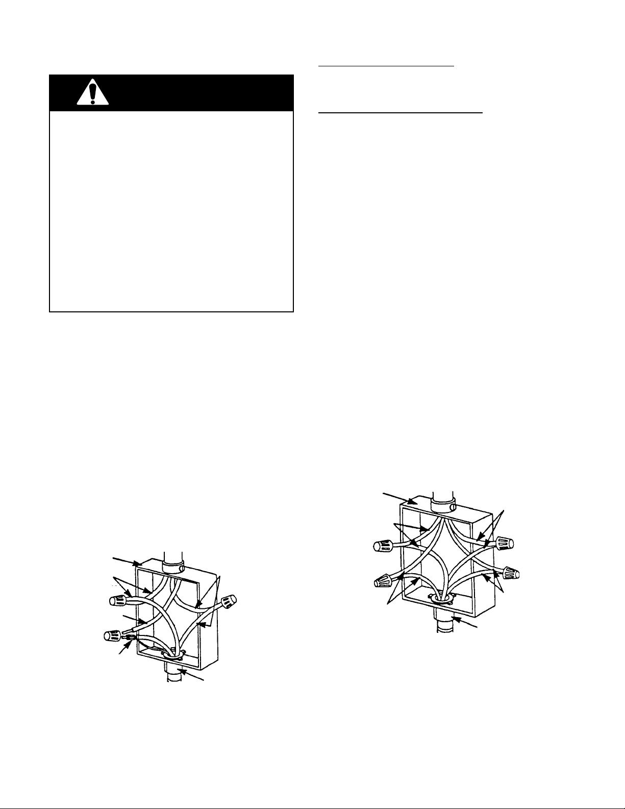
4. Connect the ends of the black wires together with twist-on connectors (see the
illustration below).
5. Connect the ends of the red wires together
with twist-on connectors.
cable from
power supply
junction box
red wires
black wires
If local codes DO permit connecting the cabinet-grounding conductor to a neutral junction
box wire, perform steps 6 and 7.
If local codes DO NOT permit connecting the
cabinet-grounding conductor to a neutral junction box wire, or if you are connecting the
appliance to a 4-wire electrical system, perform steps 8 through 11.
6. Connect the factory-crimped bare and
white electrical wires coming from the
appliance conduit cable to the white (neutral) wire inside the junction box (see the
illustration below).
7. Replace the junction box cover.
8. Separate the factory-crimped bare and
white electrical wires coming from the
appliance conduit cable.
9. Connect the white appliance wire to the
white (neutral) wire inside the junction
box.
10. Connect the bare grounding wire from the
appliance to a grounded wire inside the
junction box. IMPORTANT: Do not con-
nect the bare grounding wire to the
white (neutral) wire in the junction box.
11. Replace the junction box cover.
cable from
power supply
junction box
white wires
red wires
white wire
white & bare
grounding
appliance wires
factory crimped cable from
oven
Crimped Grounding Conductors
To White (Neutral) Wire
U.L.-listed
connector
conduit
2-2
bare
grounding
appliance wires
cable from
oven
Separate Grounding Conductors
To White (Neutral) & Bare Wires
U.L.-listed
conduit
connector
black wires
Page 15
REMOVING & REINSTALLING THE OVEN DOOR
WARNING
PERSONAL INJURY HAZARD
• Use both hands to remove oven doors.
• Do not use the handle or any portion of the
front frame or trim for lifting.
• Because of the weight and size of the
oven, two or more people are required to
move and safely install it.
Failure to properly grasp the oven doors or to
lift the oven properly could result in personal
injury or damage to the product.
CAUTION: Do not remove the shipping base
or the shipping feet at the front lower corners of the oven. The shipping feet will
protect the lower oven trim until the oven is
inserted into the cabinet cutout.
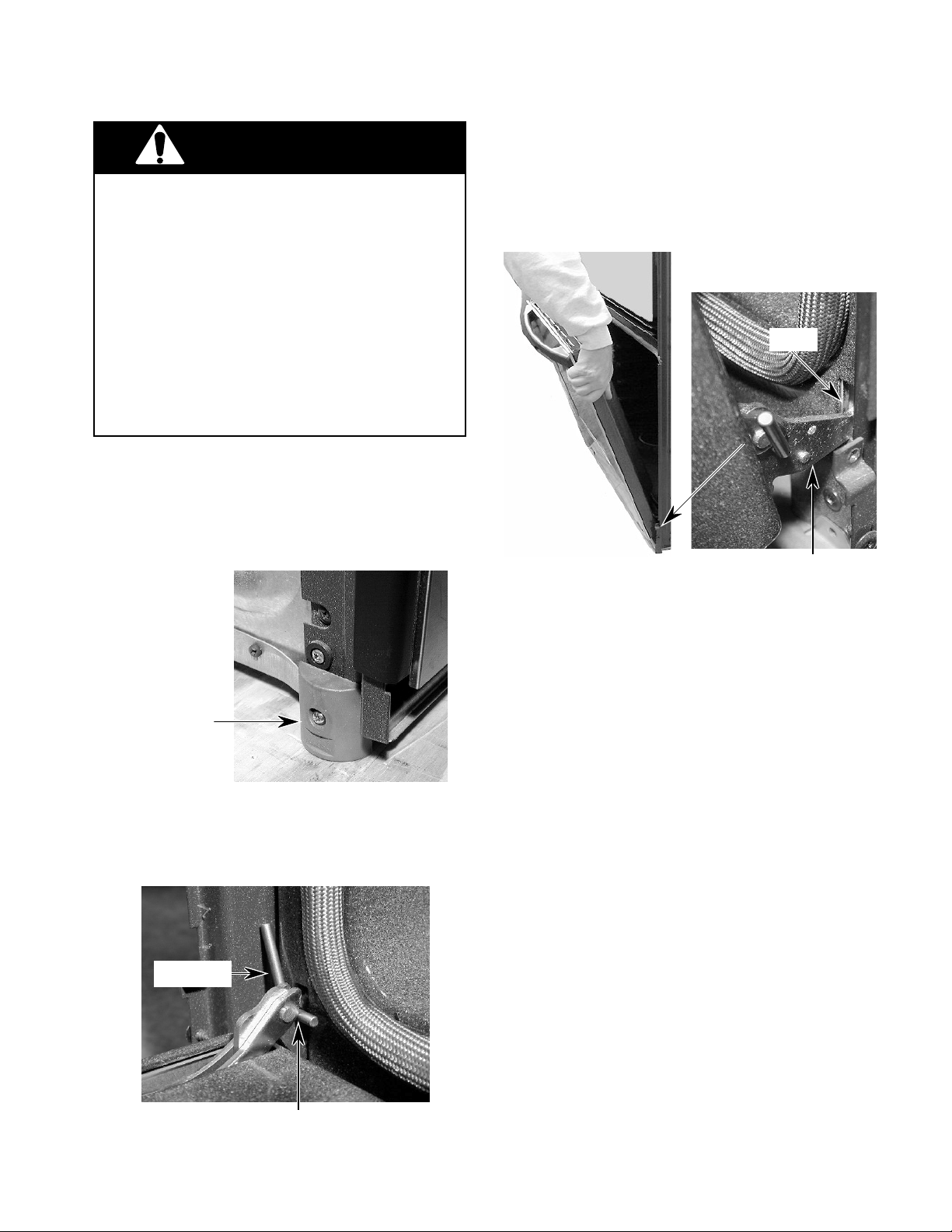
2. Close the oven door as far as the two pins
will allow.
3. Grasp the sides of the door and lift the door
until it stops, then pull the hinge hangers
out of the slots.
Slot
Hinge Hanger
Shipping Foot
To remove the oven door:
1. Install a pin in the hole of each oven door
hinge hanger.
Door Pin
To reinstall the oven door:
1. Grasp the sides of the door and tilt it back
at a slight angle, then insert the hinge
hangers into the hinge slots as far as they
will go.
2. Rotate the top of the door towards the
oven so the hinge hangers fit onto the
support pins.
3. Close the oven door as far as the pins will
allow, and make sure that the hinge hangers are fully seated on the support pins. If
they are not seated properly, the door will
not close tightly and may be off-center. To
seat the hinge hangers, open the door
slightly, and push in on the bottom until the
hangers are fully seated.
4. Open the oven door to its fully open position and remove the two hinge hanger
pins.
5. Close the oven door completely and check
it for proper operation and alignment.
Door Pin Into Hinge Hanger Hole
2-3
Page 16
OVEN / COOKTOP
COMBINATION-APPROVED INSTALLATION
The following built-in ovens are approved for installation over electric and gas cooktops, as noted.
U.S. MODELS
BUILT-IN OVENS
KEBI141D / KEBS147D / KEBI171D / KEBS177D / KEBI101D
KEBS107D / GBS277PD / GBS307PD / RBS240PD / RBS245PD
RBS270PD / RBS275PD / RBS277PD / RBS305PD / RBS307PD
ELECTRIC COOKTOPS GAS COOKTOPS
KECC563H KGCT055G
KECC501G KGCT305G
KECC502G KGCT365G
KECC507G KGCT366G
KECC508G GLT3014G
KECC562G GLT3614G
KECC576G GLT3615G
KECC568G KGCS105G
RCC3024G KGCS166G
GJC3034G KGCS127G
GJC3634G SCS3004G
KECS100G SCS3014G
KECS161G SCS3614G
RCS3004G KGCT305E
RCS3014G KGCT365E
RCS3614G KGCT366E
GJ8646XD SC8640ED
KECC501B SC8830EB
KECC502B SC8836EB
KECC507B GL8856EB
KECC560B
KECC567B
GJ8640XB
RC8600XB
RC8640XB
RC8200XB
RC8400XB
KECS100S
CANADIAN MODELS
BUILT-IN OVENS
YKEBS177D / YKEBS107D / YKEBI101D / YGBS277PD
YRBS275PD / YRBS277PD / YRBS305PD / YRBS307PD
ELECTRIC COOKTOPS
YKECC502G
YKECC507G
YKECC567G
GJC3034G
GJC3634G
RCC3024G
RCS3014G
2-4
Page 17
THEORY OF OPERATION
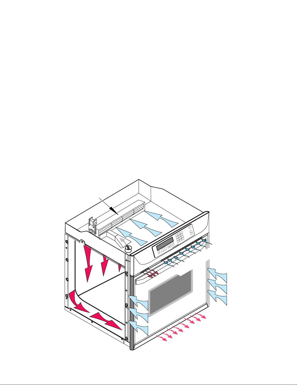
AIR FLOW
Intake air is drawn into the oven at two locations: through the control panel vent, (over the
latch assembly and the inner chassis top), and
through the side mounting rails (over the oven
sides and around the back). Air also enters the
oven at the back through the openings on the
upper section of the rear cover. At this point,
the air from the sides and the top mix. The air
is then pulled through the blower, down the
back of the unit between the outer and inner
rear covers, and out the front of the unit via the
bottom vent trim.
Air from the blower is forced over the cavity
vent. The pressure differential causes air to be
drawn from the cavity, where the air exits
through a small opening on the left side of the
control panel vent.
Air passes through the oven door by a combination of natural and forced convection. Air
enters the door through the bottom slots, and
passes between the outer glass, and the angled
inner glass. This air exits through the top slots
in the door via natural convection. Air also
enters the bottom of the door, and is drawn
between the two pieces of inner door glass,
where it exits through the top slots in the upper
part of the door. This air is then drawn into the
blower, and is forced down the back of the unit
between the inner and outer chassis covers,
and finally out the bottom vent.
The purpose of the convection fan is to circulate hot air inside the oven cavity, not to evacuate the air. Thus, the air flow for the convection
models and the non-convection models, is the
same.
BLOWER
INTAKE AIR
EXHAUST AIR
INTAKE AIR
OVEN
3-1
EXHAUST AIR
Page 18
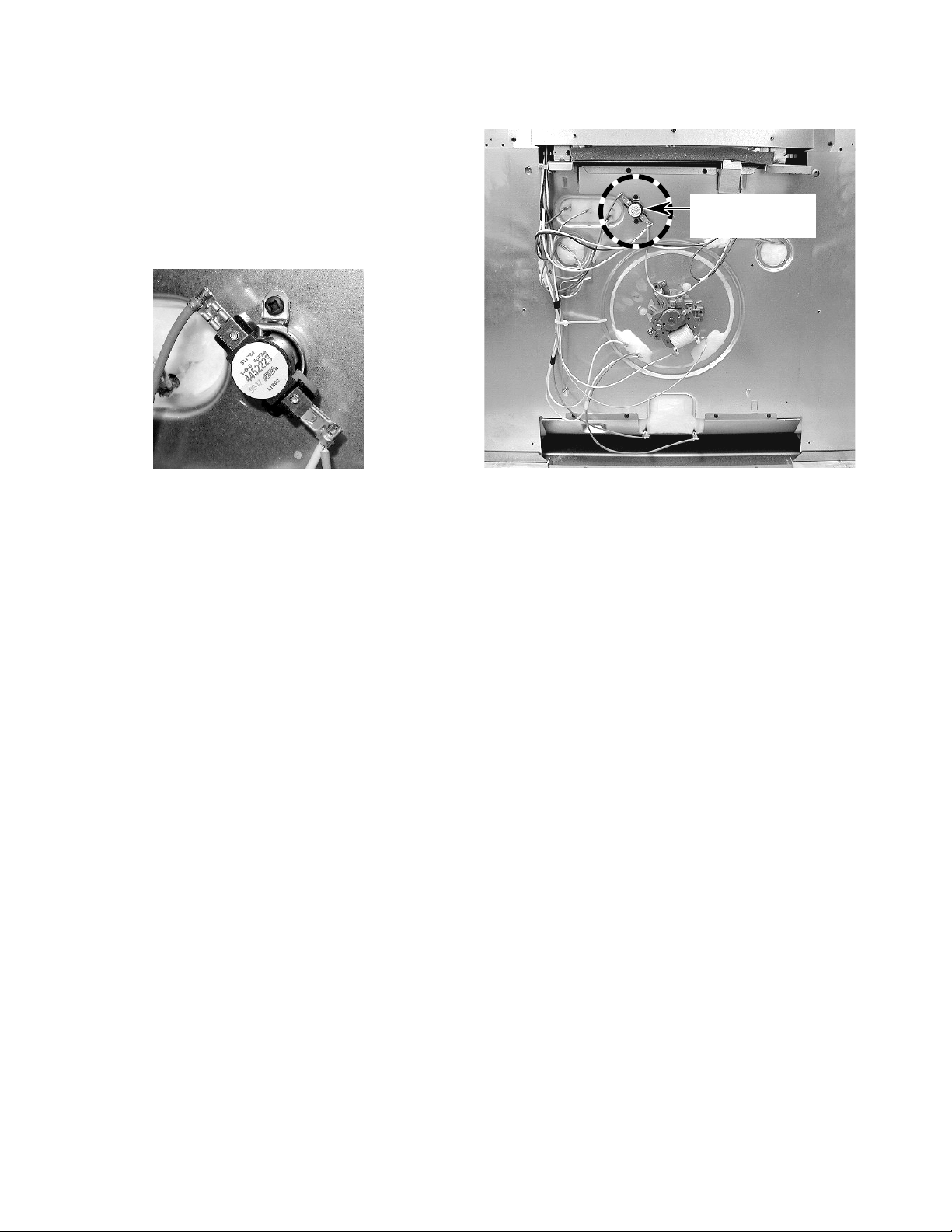
THE OVEN SHUTDOWN THERMAL FUSE
The thermal fuse is located on the rear of the
oven at the indicated location. The oven shutdown thermal fuse opens L2 to the oven if the
temperature at the rear panel exceeds 160˚C/
320˚F. The fuse is a one-time, non-resettable
safety device.
Oven Shutdown
Thermal Fuse
Oven Shutdown Thermal Fuse
BACK OF OVEN
3-2
Page 19

THE OVEN DOOR LATCH ASSEMBLY
The door latch solenoid operates on a 120-volt
dc pulse from the electronic control board.
When the solenoid plunger is retracted, the
oven door is in the “unlocked” position. When
the solenoid plunger is extended, the oven
door is in the “locked” position. When the door
lock switch is open, the control senses that the
door is “unlocked.” When the door lock switch
closes, the control senses that the door is
locked. The door lock switch, mounted on the
solenoid bracket, is in the N.O. (normallyopen) position.
Door Lock Solenoid
Door Lock Switch
Oven Light Switch
During the self-clean cycle, the control board
sends a 120-volt dc pulse to the solenoid
windings, which extends the plunger (pushes it
out), and moves the latch arm to lock the oven
door. The movement of the arm also actuates
the door lock switch arm, and closes it. When
the self-clean cycle is over, the control board
sends a 120-volt dc pulse to the solenoid, the
plunger is retracted (pulled in), the latch arm
releases the door, and the door lock switch
opens.
Door Lock Solenoid
Plunger Retracted
Door Open & Unlocked
Door Pin Out
Plunger Extended
Door Pin In
Door Closed & Locked
3-3
Page 20

HOW THE SELF-CLEAN CYCLE WORKS
The Self-Clean cycle uses high heat to burn
away soil and grease from inside the oven.
During this cycle, the oven will get much hotter
than it does under normal baking and broiling
conditions (see the following chart).
875˚F (468˚C)
CLEANING CYCLE
OVEN SHUTS OFF
(NORMAL BROILING TEMPERATURE)
TEMPERATURE
DOOR LOCKS
START 1 2 3 STOP
TIME (IN HOURS)
DOOR UNLOCKS
(FAN STAYS ON)
The oven is preset for a 3-
1
/2 hour Self-Clean
cycle. However, you can adjust this cycle time
to between 2-1/2 and 4-1/2 hours. The chart
shows a normal 3-1/2 hour Self-Clean cycle.
Note that although the heating turns off after 3hours, the door will remain locked for an additional 1/2 hour so the oven can cool sufficiently.
If the latch switch is not satisfied during the
clean operation, the cycle is terminated, and
the display will show “close door” on convection models. On non-convection models, “door”
will be displayed (see the strip circuit below).
DOOR LOCK
SOLENOID
NL2
L1
BK
PULSE
RELAY
LOCK
UNLOCK
Y
R
OUT BROIL–1000W
BU
OR
GY/W
IN BROIL–1667W
BAKE–2000W
R/W
BU
OR
M
BLOWER
W
25A/240V
R
T.O.D.
W
3-4
Page 21

COMPONENT ACCESS
This section instructs you on how to service each component inside the Electric Built-In Single
Oven. The components and their locations are shown below.
COMPONENT LOCATIONS
Blower Motor
Power Supply Wiring
Terminal Block
Light Transformer
Oven Control/
Display Boards
Control Power
Transformer
Broil Element
Convection Bake
Element & Fan Motor
Bake Element
(Hidden)
Door Latch Assembly
Oven Temperature
Sensor
Oven Shutdown
Thermal Fuse
(Rear Of Oven)
Halogen Light (2)
4-1
Page 22

REMOVING THE OVEN CONTROL/DISPLAY BOARDS,
AND THE TOUCH PANEL ASSEMBLY
5. Remove the screws from the oven control
WARNING
ELECTRICAL SHOCK HAZARD
Disconnect power before servicing.
Replace all panels before operating.
Failure to do so could result in death or
electrical shock.
CAUTION: When you work on the built-in
oven, be careful when handling the sheet metal
parts. Sharp edges may be present, and you
can cut yourself if you are not careful.
1. Disconnect the electrical power to the
oven.
2. Open the oven door.
3. Remove the bottom screw from each of
the two side trim pieces (see below).
panel.
Control
Panel
Screw
6. To remove the oven control panel, pull it
out at the bottom, and lift and unhook it
from the oven cabinet support at the top.
Oven
Control
Panel
Lift Off
Top
Support
4. To remove the side trim, pull the bottom
out approximately 2˝, and slide the top
down to free it from the control panel.
Side Trim Screw
(1 On Each Side)
Pull Side Trim
Down & Away
From Control
Panel
Pull Out Bottom
Of Side Trim
7. Disconnect the wire connectors from the
control board and set the panel assembly
face down on a padded surface to protect
the finish.
5 Wire Connectors
4-2
Page 23

8. To remove the oven control/display
boards:
b) Remove the six screws from the control
panel bracket and remove the bracket.
a) Remove the five mounting screws.
Screws
Screws
Lift Ends Of
Locking Arm
b) Lift the ends of the locking arm and
disconnect the ribbon cable from its
connector.
NOTE: The control and display boards are
designed to be replaced as an assembly.
9. To remove the touch panel assembly:
a) Remove the seven spacers and the
cardboard shield from the panel.
Bracket Screw (1 of 6)
Control Panel Bracket
c) Peel the touch panel off the bracket.
Touch Panel
Bracket
REASSEMBLY NOTE: When you reinstall the
oven control panel, use the following procedure (refer to the photos on the previous page,
as necessary):
1. Reconnect the wiring to the control board
terminals.
2. Hook the ends of the control panel over
the rubber tips of the brackets.
3. Push the bottom of the control panel in and
position the plastic air duct under the lip of
the panel.
Spacer (1 of 7) Cardboard Shield
Air Duct
Bottom Lip Of Control Panel
4. Align the mounting holes and install the
two side screws in the control panel.
4-3
Page 24

REMOVING THE POWER SUPPLY WIRING TERMINAL
BLOCK AND THE BLOWER MOTOR
4. Remove the screw from the conduit clamp
WARNING
ELECTRICAL SHOCK HAZARD
Disconnect power before servicing.
Replace all panels before operating.
Failure to do so could result in death or
electrical shock.
CAUTION: When you work on the built-in
oven, be careful when handling the sheet metal
parts. Sharp edges may be present, and you
can cut yourself if you are not careful.
1. Disconnect the electrical power to the
oven.
2. Remove the side trim from the oven (see
page 4-2, steps 1 through 4 for the procedure).
and remove the clamp.
5. Remove the 6 screws from the top rear
oven cabinet cover.
Conduit
Clamp
Top Rear Cover
(6 Screws)
NOTE: Before you move the oven from its
mounting location, remove the oven door to
make it easier to move (see page 2-3 for the
procedure).
3. Remove the oven cabinet mounting screws
and pull the oven out of its mounting
location so that you can access the back.
Cabinet Mounting Screw
(1 Screw On Each Side)
6. To remove the power supply wiring
terminal block:
a) Remove the hex nuts from the wire
terminal studs and remove the wires
from the studs.
b) Remove the two mounting screws from
the terminal block and remove it from
the top of the oven.
Power Supply
Wiring Terminal Block
Mounting
Screws
Wires
4-4
Page 25

7. To remove the blower motor assembly:
a) Remove the rear cover from the oven
(11 screws) .
Screw (1 of 11)
b) Remove the four screws from the blower
cover and remove the cover.
Rear Cover
2 Screws Blower Cover 2 Screws
c) Disconnect the two wires from the blow-
er motor terminals.
2 Wires
Blower Motor Assembly
5 Mounting Screws
d) Remove the five mounting screws.
4-5
Page 26

REMOVING THE OVEN LIGHT TRANSFORMER
& THE CONTROL POWER TRANSFORMER
3. Remove the mounting screw from the
WARNING
ELECTRICAL SHOCK HAZARD
transformer you are servicing and unhook
the tab from the oven chassis slot.
Disconnect power before servicing.
Replace all panels before operating.
Failure to do so could result in death or
electrical shock.
CAUTION: When you work on the built-in
oven, be careful when handling the sheet metal
parts. Sharp edges may be present, and you
can cut yourself if you are not careful.
1. Disconnect the electrical power to the
oven.
2. Remove the control panel from the oven
(see page 4-2, steps 1 through 6 for the
procedure). Position the control panel forward so you can access either transformer.
Oven Light & Control Power Transformers
Transformer
Light
Transformer
Control Pwr
Transformer
4. Disconnect the four wires from the LOAD
and LINE terminals of the transformer.
NOTE: The LOAD and LINE terminals are
different sizes so that you cannot make a
mistake when reconnecting the wires (see
below).
Light Transformer
Wht & Blk (Small)
Control Power Transformer
(2) Red (Small)
Screws
4-6
Wht & Blk (Large)
(2) Blue
(Large)
Page 27

REMOVING THE OVEN DOOR LATCH ASSEMBLY
WARNING
ELECTRICAL SHOCK HAZARD
Disconnect power before servicing.
Replace all panels before operating.
Failure to do so could result in death or
electrical shock.
3. Open the oven door and remove the two
front oven door latch mounting screws
from the air vent.
Oven Door Latch Assembly
CAUTION: When you work on the built-in
oven, be careful when handling the sheet metal
parts. Sharp edges may be present, and you
can cut yourself if you are not careful.
1. Disconnect the electrical power to the
oven.
2. Remove the control panel from the oven
(see page 4-2, steps 1 through 6 for the
procedure).
Air Vent
2 Air Vent Screws
4. Remove the wires from the terminals of
the solenoid and the latch and door
switches.
Solenoid
Latch Switch
Door Switch
2 Top Screws
5. Remove the two top screws from the oven
door latch assembly and remove the assembly.
4-7
Page 28

REMOVING AN OVEN HALOGEN LIGHT &
THE OVEN TEMPERATURE SENSOR
3. To remove an oven halogen light:
WARNING
ELECTRICAL SHOCK HAZARD
Disconnect power before servicing.
Replace all panels before operating.
Failure to do so could result in death or
electrical shock.
CAUTION: When you work on the built-in
oven, be careful when handling the sheet metal
parts. Sharp edges may be present, and you
can cut yourself if you are not careful.
1. Disconnect the electrical power to the
oven.
2. Open the oven door and remove the racks
from inside the oven.
a) Remove the lens from the halogen light
socket by lifting the end near the mounting screw and unsnapping it.
b) Remove the screw from the halogen
light assembly.
Lift Lens Here
Halogen Light
Assembly
Mounting Screw
c) Pull the halogen bulb out of the socket.
Oven Temperature
Sensor & Halogen
Lights
Halogen Bulb
Socket Assembly
4-8
Page 29

d) Pull the halogen socket assembly out
of the oven liner and cut the wires near
the socket terminals.
Cut Wires Here
4. To remove the oven temperature sen-
sor:
a) Remove the two mounting screws from
the oven temperature sensor and pull
the connector out of the mounting hole
in the oven liner.
Screws
Oven
Temperature
Sensor
b) Disconnect the sensor connector from
the main wire harness connector.
e) Cut the new halogen light socket wires
to the proper length.
f) Remove 3/8˝ of insulation from the cut
wires on the wire harness and the halogen light socket. Splice the halogen
light socket wires to the harness wires,
and twist two wire nuts over the bare
wire ends.
Sensor
Connector
4-9
Page 30

REMOVING THE BROIL ELEMENT
WARNING
ELECTRICAL SHOCK HAZARD
Disconnect power before servicing.
Replace all panels before operating.
Failure to do so could result in death or
electrical shock.
CAUTION: When you work on the built-in
oven, be careful when handling the sheet metal
parts. Sharp edges may be present, and you
can cut yourself if you are not careful.
1. Disconnect the electrical power to the
oven.
2. Open the oven door and remove the racks
from inside the oven.
3. Remove the two front bracket screws and
two rear bracket screws from the broil
element.
Front Bracket
Screws
Rear Bracket
Screws
4. Carefully pull the element forward so that
the wires are through the oven liner holes,
and disconnect the wires from the terminals.
4 Element Wires
Broil
Element
4-10
Page 31

REMOVING THE MEAT PROBE JACK
WARNING
ELECTRICAL SHOCK HAZARD
Disconnect power before servicing.
Replace all panels before operating.
Failure to do so could result in death or
electrical shock.
CAUTION: When you work on the built-in
oven, be careful when handling the sheet metal
parts. Sharp edges may be present, and you
can cut yourself if you are not careful.
1. Disconnect the electrical power to the
oven.
2. Remove the racks from inside the oven.
5. Remove the meat probe jack access panel
from the right side of the unit. Use a pair of
small cutters to clip the bridge.
Clip Bridge
Meat Probe
Jack
Access
Panel
Right Side
Of Oven
Meat Probe Jack
3. Remove the hex nut from the meat probe
jack.
Meat Probe
Jack
Hex Nut
4. Pull the oven out of its mounting location
approximately 8˝, (see page 4-4 steps 1
through 3 for the procedure), so that you
can access the meat probe jack access
panel on the right side.
6. Push aside the insulation, pull the meat
probe jack out of the access hole, and
remove the star washer from the jack.
7. Cut the wires near the lugs of the old meat
probe jack, then use two small wire nuts,
and splice the new jack to the oven wires.
Star Washer
Meat Probe Jack
REASSEMBLY NOTE: When you install the
new jack, be sure to place the star washer from
the old jack on the threaded end of the new
one. After you have installed the jack, mount
the access cover with two #8 x 1/4˝ screws.
Access Cover
#8 x 1/4˝ Screw
4-11
Page 32

REMOVING THE HIDDEN BAKE ELEMENT
WARNING
ELECTRICAL SHOCK HAZARD
Disconnect power before servicing.
Replace all panels before operating.
Failure to do so could result in death or
electrical shock.
CAUTION: When you work on the built-in
oven, be careful when handling the sheet metal
parts. Sharp edges may be present, and you
can cut yourself if you are not careful.
1. Disconnect the electrical power to the
oven.
2. Pull the oven out of its mounting location
so that you can access the rear cover (see
page 4-4, steps 1 through 3 for the procedure).
4. Remove the four screws from the hidden
bake element cover flange.
Cover Flange
& 2 Screws
5. Bend the cover flanges down as far as
they will go.
Bend Cover
Flange Down
Cover Flange
& 2 Screws
Bend Cover
Flange Down
3. Remove the rear cover from the oven (see
page 4-5 for the procedure).
Hidden Bake Element
6. Use a pen knife or a single-edged razor
blade and cut the insulation blanket, as
shown. Be sure to separate the insulation
blanket as cleanly as possible.
Cut Insulation Blanket
7. Carefully move the insulation blanket out
of the way so that you can access the
hidden bake element mounting bracket.
4-12
Page 33

8. Remove the four mounting bracket screws
and the two hidden bake element bracket
screws.
Remove Two Screws
Remove Four Screws
9. Carefully pull the hidden bake element
and its mounting bracket out of the oven.
Pull Out Hidden Bake Element
4-13
Page 34

REMOVING THE CONVECTION BAKE ELEMENT
AND THE FAN MOTOR ASSEMBLY
position the cover with the notch as shown
WARNING
when you reinstall it.
ELECTRICAL SHOCK HAZARD
Disconnect power before servicing.
Replace all panels before operating.
Failure to do so could result in death or
electrical shock.
CAUTION: When you work on the built-in
oven, be careful when handling the sheet metal
parts. Sharp edges may be present, and you
can cut yourself if you are not careful.
1. Disconnect the electrical power to the
oven.
2. To make servicing easier, remove the
oven door from the unit (see page 2-3 for
the procedure).
3. Remove the racks from inside the oven.
Screw 1 of 3
Convection
Cover
Notch
5. To remove the convection bake ele-
ment:
a) Remove the two screws from the con-
vection bake element.
b) Pull it forward so you can access the
terminals.
c) Disconnect the wires from the element
terminals.
Screw
Convection Bake
Element
Convection Bake
Element & Fan Motor
4. Remove the three screws from the convection cover and remove the cover from
the rear of the oven liner. Note the location
of the notch in the cover. Be sure to
Screw
Element Terminals
4-14
Page 35

6. To remove the convection fan motor:
a) If not already done, remove the con-
vection cover and the convection bake
element from the rear of the oven liner
(see page 4-14).
b) Use a 10 mm (7/16˝) socket and re-
move the hex nut from the convection
fan. NOTE: The nut has a left-rotation
thread for removal.
Convection
Fan
10 mm
(7/16˝)
Hex Nut
c) Remove the three front convection fan
motor screws from the rear of the oven
liner.
f) Remove the two rear convection fan
motor mounting screws from the oven,
and remove the motor from the rear of
the oven.
Convection
Fan Motor
Convection Fan Motor
Rear Screw (1 of 2)
Convection
Fan Motor
Front Screw
(1 of 3)
d) Pull the oven out of its mounting loca-
tion (see page 4-4, steps 1 through 3 for
the procedure) so that you can access
the rear cover.
e) Remove the rear cover from the oven
(see page 4-5 for the procedure).
Convection Fan
Motor Terminals
4-15
Page 36

REMOVING THE OVEN SHUTDOWN THERMAL FUSE
WARNING
ELECTRICAL SHOCK HAZARD
Disconnect power before servicing.
Replace all panels before operating.
Failure to do so could result in death or
electrical shock.
CAUTION: When you work on the built-in
oven, be careful when handling the sheet metal
parts. Sharp edges may be present, and you
can cut yourself if you are not careful.
1. Disconnect the electrical power to the
oven.
2. Pull the oven out of its mounting location,
(see page 4-4 steps 1 through 3 for the
procedure), so that you can access the
rear cover.
Oven Shutdown Thermal Fuse
4. Disconnect the wires from the thermal
fuse terminals.
Mounting Screw (1 of 2)
3. Remove the rear cover from the oven (see
page 4-5 for the procedure).
Oven Shutdown
Thermal Fuse
5. Remove the two screws and remove the
fuse from the rear of the oven.
4-16
Page 37

REMOVING THE OVEN DOOR GLASS, HINGES, & HANDLE
CAUTION: When you work on the built-in
oven, be careful when handling the sheet metal
parts. Sharp edges may be present, and you
can cut yourself if you are not careful.
1. Remove the oven door from the oven (see
page 2-3 for the procedure).
2. Place the oven door on a padded work
surface with the front decorative glass
facing down.
3. Remove the two top door liner screws and
the two door glass bracket screws, and lift
the liner assembly off the decorative door
glass and handle.
Top Liner Screws
4. To remove the outer door glass:
a) Remove the three outer glass holder
screws and two outer glass bracket
screws from the door liner.
b) Lift the outer glass with the glass holder
off the door liner.
c) Remove the bracket.
Outer Glass Holder Screws
Outer Door Glass
Outer Glass Bracket Screws
Door Glass
Bracket Screws
5. To remove the center door glass, re-
move the bottom bracket, (it is loose), and
slide the two top corners of the glass out of
the door liner slots.
Center Door Glass Corners
Center Door Glass
Remove Loose Bracket
Continued on the next page.
4-17
Page 38

6. To remove the hinges and the inner
door glass:
NOTE: You will have to remove both hinges to
remove the inner door glass from the oven door
liner.
d) Remove the insulation and the inner
door glass.
a) Lift either side of the door liner, remove
the two door hinge screws, and remove
the hinge.
Hinge Screws (4 total)
Inner Door Glass
Inner Door Glass Cover
b) Lift the other side of the door liner,
remove the two screws for the other
hinge, and remove the hinge.
c) Lift the inner door glass liner cover off
the liner.
Inner Door Glass
Insulation
7. To remove the door handle, remove the
two door handle screws from the bracket.
Door Handle
Bracket & Screws
(2 each)
4-18
Page 39

REMOVING THE OVEN DOOR GASKET
CAUTION: When you work on the built-in
oven, be careful when handling the sheet metal
parts. Sharp edges may be present, and you
can cut yourself if you are not careful.
1. Open the oven door to its fully open position.
2. Remove the screw from the door gasket
bracket and remove the bracket from the
oven.
Door Gasket
3. Pull the ends of the gasket out of the liner
holes and pull the clips out of their liner
holes.
Gasket Clips
REASSEMBLY NOTE: When you install the
new gasket, make sure that all of the clips are
seated in their liner holes, and that the ends of
the gasket are pushed fully into their holes. Use
the pointed end of a pencil to push the gasket
ends into the holes.
Screw
Gasket Bracket
4-19
Page 40

— NOTES —
4-20
Page 41

COMPONENT TESTING
WARNING
Before testing any of the components, perform
the following checks:
• The most common cause for control failure is
corrosion on connectors. Therefore, disconnecting and reconnecting wires will be necessary throughout test procedures.
• All tests/checks should be made with a VOM
or DVM having a sensitivity of 20,000 ohmsper-volt DC, or greater.
WARNING
ELECTRICAL SHOCK HAZARD
Disconnect power before servicing.
Replace all panels before operating.
Failure to do so could result in death or
electrical shock.
BLOWER MOTOR
• Check all connections before replacing components, looking for broken or loose wires,
failed terminals, or wires not pressed into
connectors far enough.
• Voltage checks must be made with all connectors attached to the boards.
• Resistance checks must be made with power
cord unplugged from outlet, and with wiring
harness or connectors disconnected.
ELECTRICAL SHOCK HAZARD
Disconnect power before servicing.
Replace all panels before operating.
Failure to do so could result in death or
electrical shock.
OVEN TEMPERATURE SENSOR
Refer to page 4-4 for the procedure for servicing the blower motor.
1. Disconnect the electrical power to the
oven.
2. Disconnect the wires from the blower motor
terminals.
3. Set the ohmmeter to the R x 1 scale.
4. Touch the ohmmeter leads to the motor
terminals. The meter should indicate between 14 and 18 Ω.
Refer to page 4-8 for the procedure for servicing the oven temperature sensor.
1. Disconnect the electrical power to the
oven.
2. Disconnect the oven temperature sensor
connector from the oven connector.
3. Set the ohmmeter to the R x 1K scale.
4. Touch the ohmmeter leads to the sensor
connector pins. The meter should indicate
1080 Ω @ 70˚F.
5-1
Page 42

WARNING
WARNING
ELECTRICAL SHOCK HAZARD
Disconnect power before servicing.
Replace all panels before operating.
Failure to do so could result in death or
electrical shock.
CONVECTION BAKE ELEMENT
Refer to page 4-14 for the procedure for servicing the convection bake element.
1. Disconnect the electrical power to the
oven.
2. Disconnect the wires from the convection
bake element terminals.
3. Set the ohmmeter to the R x 1 scale.
4. Touch the ohmmeter leads to the element
terminals. The meter should indicate between 28 and 35 Ω.
ELECTRICAL SHOCK HAZARD
Disconnect power before servicing.
Replace all panels before operating.
Failure to do so could result in death or
electrical shock.
CONVECTION FAN MOTOR
Refer to page 4-14 for the procedure for servicing the convection fan motor.
1. Disconnect the electrical power to the
oven.
2. Disconnect the wires from the convection
fan motor terminals.
3. Set the ohmmeter to the R x 1 scale.
4. Touch the ohmmeter leads to the motor
terminals. The meter should indicate between 8 and 12 Ω.
5-2
Page 43

WARNING
WARNING
ELECTRICAL SHOCK HAZARD
Disconnect power before servicing.
Replace all panels before operating.
Failure to do so could result in death or
electrical shock.
BROIL ELEMENT
Outer
Element
Refer to page 4-10 for the procedure for servicing the broil element.
1. Disconnect the electrical power to the
oven.
2. Disconnect the wires from the broil element terminals.
3. Set the ohmmeter to the R x 1 scale.
4. Touch the ohmmeter leads to the inner
broil element terminals. The meter should
indicate between 45 and 55 Ω.
Inner
Element
Outer
Element
ELECTRICAL SHOCK HAZARD
Disconnect power before servicing.
Replace all panels before operating.
Failure to do so could result in death or
electrical shock.
BAKE ELEMENT
Refer to page 4-12 for the procedure for servicing the hidden bake element.
1. Disconnect the electrical power to the
oven.
2. Disconnect the wires from the bake element terminals.
3. Set the ohmmeter to the R x 1 scale.
4. Touch the ohmmeter leads to the element
terminals. The meter should indicate between 25 and 30 Ω.
5. Touch the ohmmeter leads to the outer
broil element terminals. The meter should
indicate between 45 and 55 Ω.
5-3
Page 44

WARNING
WARNING
ELECTRICAL SHOCK HAZARD
Disconnect power before servicing.
Replace all panels before operating.
Failure to do so could result in death or
electrical shock.
OVEN DOOR LATCH ASSEMBLY
Solenoid
Latch
Switch
Refer to page 4-7 for the procedure for servicing the oven door latch assembly.
1. Disconnect the electrical power to the
oven.
2. Disconnect the wires from the door latch
assembly component under test.
3. Set the ohmmeter to the R x 1 scale.
4. To test the solenoid, touch the ohmme-
ter leads to the terminals. The meter should
indicate between 47 and 54 Ω.
Door
Switch
ELECTRICAL SHOCK HAZARD
Disconnect power before servicing.
Replace all panels before operating.
Failure to do so could result in death or
electrical shock.
OVEN SHUTDOWN THERMAL FUSE
Refer to page 4-16 for the procedure for servicing the oven shutdown thermal fuse.
1. Disconnect the electrical power to the
oven.
2. Disconnect the wires from the oven shutdown thermal fuse terminals.
3. Set the ohmmeter to the R x 1 scale.
4. Touch the ohmmeter leads to the oven
shutdown thermal fuse terminals. The
meter should indicate continuity (closed
circuit).
5. To test the door or latch switch:
a) Touch the ohmmeter leads to the fol-
lowing terminals (shown embossed on
the switch). The meter should indicate:
COM to N.O. = infinity (no continuity)
COM to N.C. = 0 Ω (continuity)
b) Press the switch actuator button and
touch the ohmmeter leads to the following terminals. The meter should indicate:
COM to N.O. = 0 Ω (continuity)
COM to N.C. = infinity (no continuity)
5-4
Page 45

WARNING
ELECTRICAL SHOCK HAZARD
Disconnect power before servicing.
Replace all panels before operating.
Failure to do so could result in death or
electrical shock.
Refer to page 4-6 for the procedure for servicing the oven light & control power transformers.
1. Disconnect the electrical power to the
oven.
2. Disconnect the wires from the transformer
under test.
3. Set the ohmmeter to the R x 1 scale.
4. To test the oven light transformer:
OVEN LIGHT & CONTROL POWER
TRANSFORMERS
LOAD
LINE
a) Touch the ohmmeter leads to the LINE
terminals. The meter should indicate
between 40 and 45 Ω.
b) Touch the ohmmeter leads to the LOAD
terminals. The meter should indicate
less than 1 Ω.
5. To test the control power transformer:
a) Touch the ohmmeter leads to the LINE
terminals. The meter should indicate
between 85 and 90 Ω.
b) Touch the ohmmeter leads to the LOAD
terminals. The meter should indicate
between 1 and 6 Ω.
5-5
Page 46

— NOTES —
5-6
Page 47

DIAGNOSIS & TROUBLESHOOTING
DIAGNOSTICS
Before servicing, perform the following checks:
• The most common cause for control failure is
corrosion on connectors. Therefore, disconnecting and reconnecting wires will be necessary throughout test procedures.
• All tests/checks should be made with a VOM
or DVM having a sensitivity of 20,000 ohmsper-volt DC, or greater.
• Check all connections before replacing components, looking for broken or loose wires,
failed terminals, or wires not pressed into
connectors far enough.
• Voltage checks must be made with all connectors attached to the boards.
• Resistance checks must be made with power
cord unplugged from outlet, and with wiring
harness or connectors disconnected.
• Is the oven in the “Sabbath Mode”? If so,
“SAB” will appear in the display. Press and
hold the 6 touchpad for 5 seconds to end the
Sabbath Mode.
• To check for the last five Fault codes: Press
and hold the 0 touchpad to access the previous codes. Numeric touchpads 0 - 4 indicate
faults 1 - 5 respectively, with “0” being the
most recent code.
FAHRENHEIT (°F) TO CELSIUS (°C)
CONVERSION
The default is Fahrenheit (° F).
1. Press the BROIL pad for 5 seconds. The
temperature will be displayed in degrees
Celsius indicated by the “C” in the temperature display.
2. To return the display to degrees Fahrenheit
press the BROIL pad again for 5 seconds.
“F” will show in the temperature display.
PROGRAMMING THE CAVITY SIZE
When replacing the electronic control, be sure
to program the cavity size within 60 seconds of
power up by pressing the following touchpads:
BAKE (upper half of BAKE touchpad),
CONVECTION BROIL (lower half of BROIL
touchpad.
STOP TIME, CONV FULL MEAL, digit #7,
digit #9, TIMER SET/START, & START.
1. The size is shown in the display “-ID 24”.
2. Press the CLOCK SET/START touchpad
until the correct size is displayed.
3. Press the CANCEL touchpad (do not press
the OVEN START touchpad).
4. To verify programming, press and hold the
1 touchpad for 5 seconds.
ELECTROSTATIC DISCHARGE
(ESD) SENSITIVE ELECTRONICS
ESD problems are present everywhere. ESD
may damage or weaken the electronic control
assembly. The new control assembly may appear to work well after repair is finished, but
failure may occur at a later date due to ESD
stress.
• Use an anti-static wrist strap. Connect wrist
strap to green ground connection point or
unpainted metal in the appliance
-OR-
Touch your finger repeatedly to a green
ground connection point or unpainted metal
in the appliance.
• Before removing the part from it’s package,
touch the anti-static bag to a green ground
connection point or unpainted metal in the
appliance.
• Avoid touching electronic parts or terminal
contacts; handle electronic control assembly by edges only.
• When repackaging failed electronic control
assembly in anti-static bag, observe above
instructions.
6-1
Page 48

FAILURE/ERROR DISPLAY CODES
• Always disconnect the power to the unit
before touching the internal parts of the
oven.
FAULT
CODE
F0
F1
F2
F3
F4
F5
ERROR
CODE
All E
Codes
E0
E1
E5
E0
E1
E2
E3
E1
E0
E1
E5
E7
MEANING OF FAILURE CODE RECOMM ENDED REPAIR PROCEDURE
Default F code — No failure
Electronic control malfunction Replace control.
Key held down too long, or key is shorted
Keypad keytail not connected
Cancel key drive line open
Temperature sensor opened
Temperature sensor shorted
Oven temp too high
°
(over 301
Oven temp too high
(over 510
Meat probe malfunction - shorted
Door is open, but latch is locked
(condition exists when door switch is closed
indicating an open door, and latch switch is
closed indicating a locked door)
Self clean latch will not lock
Self clean temperature (288
reached within 45 minutes
Self clean latch will not unlock
C [575°F] in Cook mode)
°
C [950°F] in Clean mode)
°
C [550°F] ) not
Will only be displayed if user presses and holds “0” key for 5 seconds and there are no preexisting faults. Press CANCEL to clear display.
1. Check keypad connector for firm connection.
2. Press CANCEL. If error code returns after 60 sec., replace keypad.
3. Replace control.
1. Check sensor connection.
2. Measure sensor resistance (1080
If resistance is not valid, replace sensor.
3. If sensor resistance and connections are good, then the oven cavity temperature
must have exceeded a safe level. Check for welded-closed relays on the control.
1. Disconnect meat probe and measure probe resistance: (78k
37k
2. Insert probe and check for a firm connection between probe and jack (in oven cavity).
3. Check connection between jack and harness (in rear of oven).
1. Check the latch assembly:
- Check latch arm pivot joint, arm/solenoid connection, solenoid spring,
and spring washer.
2. Check the Latch Solenoid:
- Check for firm electrical connections.
- Disconnect the two wires from the solenoid and measure the resistance of
the solenoid. A small resistance (approx. 175
If the solenoid is open (
3. Check the Latch Switch: Disconnect it and use a continuity tester:
- Door latched = switch closed, continuity should read 0
- Door unlatched = switch open, continuity should read
4. Check Door Open/Closed Switch. Disconnect it and use a continuity tester:
- Door open = switch closed, continuity should read 0
- Door closed = switch open, continuity should read
5. Check power and element connections.
• Upon replacement, immediately return the
old electronic oven control. Use the mailing
label that is supplied with each new control.
Ω
at 21°C [70°F]; add 2Ωper degree).
Ω
at 32.2°C[90°F] ). If resistance is not valid, replace probe.
Ω
∞ Ω
) or shorted (0Ω) it should be replaced.
) is normal.
∞ Ω
Ω
at 15.6°C[60°F];
Ω
.
∞ Ω
.
Ω
.
.
F6
E0
Return line not connected
If switch pulse return line is not connected, electronic control will display F6 within 60 seconds
after power up. Replace control.
6-2
Page 49

CONTROL PANEL TEST LOCATIONS
COMPONENT
Door Switch
Door Lock Solenoid
(with Door Closed)
Oven Temperature Sensor
Blower
Oven Light Transformer
Oven Shutdown
Thermal Fuse
Bake Element
Inner Broil Element
Outer Broil Element
Convection Ring Element
Convection Fan Motor
Meat Probe Jack
Latch Switch
FRONT/REAR
SERVICEABLE
Front
Front
Front
Rear
Front
Rear
Rear
Front
Front
Front
Rear P1-6 (OR) to Neutral (W) 8 Ω to 12 Ω
Rear
Front
to Red Wire at Terminal Block
P5-3 (R) to Red Wire at Terminal Block
P5-2 (OR) to Red Wire at Terminal Block
P5-1 (BU) to Red Wire at Terminal Block
P5-4 (Y) to Red Wire at Terminal Block
CHECK POINTS RESULTS
P7-2 (BR) to P7-1 (TAN)
P6-1 (Y) to P6-2 (W)
P7-4 (V) to P7-6 (GN)
P1-5 (GY) to Neutral (W)
Primary Winding
Secondary Winding
P5-2 (OR) or P5-3 (R)
P7-7 (GN) to P7-8 (Y)
P7-3 (BU) to P7-1 (TAN)
Door Open = Closed Circuit
Door Closed = Open Circuit
1080 Ω @ 21°C (70°F)
Probe into Jack - Check for
78k Ω @ Room Temperature
Door Unlocked = Open Circuit
Door Locked = Closed Circuit
14 Ω to 18 Ω
40 Ω to 45 Ω
Less than1 Ω
Closed Circuit
25 Ω to 30 Ω
45 Ω to 55 Ω
45 Ω to 55 Ω
28 Ω to 35 Ω
50 Ω
RELAY LOGIC CHART
RELAY LOGIC KEY
- OFF
O
- ON
X
- CYCLING (MAX PERIOD = 60SEC)
+
- ON OR OFF
OX
Thermal Convection Models Only
6-3
Page 50

— NOTES —
6-4
Page 51

WIRING DIAGRAM & STRIP CIRCUITS
MODEL NUMBER / TECH SHEET USE
MODEL NUMBER
KEBI141D**6 4452023
KEBS147D**6 4452024
KEBI171D**6 4452023
KEBI177D**6 4452024
KEBI101D**6 4452023
KEBI107D**6 4452024
KEBC177D**6
KEBC107D**6
KEBI141D**7
KEBI141D**8
KEBI141D**9
KEBI141D**10
KEBI141D**11
KEBI141D**12
KEBS147D**7
KEBS147D**8
KEBS147D**9
KEBS147D**10
KEBS147D**11
KEBS147D**12
KEBI171D**7
KEBI171D**8
KEBI171D**9
KEBI171D**10
KEBI171D**11
KEBI171D**12
KEBS177D**7
KEBS177D**8
KEBS177D**9
KEBS177D**10
KEBS177D**11
KEBS177D**12
KEBI101D**7
KEBI101D**8
KEBI101D**9
KEBI101D**10
KEBI101D**11
KEBI101D**12
KEBS107D**7
KEBS107D**8
KEBS107D**9
KEBS107D**10
KEBS107D**11
KEBS107D**12
TECH SHEET
NUMBER
4451876D
7-1
Page 52

SCHEMATIC DIAGRAM
WIRE HARNESS SCHEMATIC
NOTES:
• When replacing the electronic control, be sure to
program the cavity size (see “Programming The
Cavity Size” on page 6-1).
• Dots indicate connections or splices.
• Circuit shown in STANDBY/OFF mode with
oven door closed.
CONTROL POWER
TRANSFORMER
L1
TEMP SENSOR
1080
AT 21 70°F)°C(
1654
AT 177 350°F)°C(
MEAT PROBE
78k
AT 15.6 0°F)°C(6
37k
AT 32.2 0°F)°C(9
THERMAL CONVECTION
MODELS ONLY
TA N
LATCH
SWITCH
(OPERATED BY
SOLENOID)
TA N
W
t°
W
t°
DOOR ON LATCH ASSY
SWITCH
GN
W
W
P3-5 P3-7 P3-2 P3-3
BK
GN
BR
BU
BK
BK
P4-1
P4-2
P1-1
V
P7-4
Y
P7-8
P7-7
P7-2
P7-3
ELECTRONIC
R
R
CONTROL
CIRCUIT
GROUND (CHASSIS)
PLUG WITH FEMALE
CONNECTOR
RECEPTACLE WITH
MALE CONNECTOR
LIGHT
BU
BU
P1-3
P6-1
+
LATCH
DRIVE
P6-2
–
P1-6
P5-4
P5-3
P5-1
P5-2
P1-5
W
Y
W
18V DC
SOLENOID
OR
Y
BAKE-2000W
R
OUT BROIL-1000W
BU
IN BROIL-1667W
OR
GY
AC DRIVE
MOTOR
RELAY COIL
RELAY
CONTACTS
HEATING
ELEMENT
–
DOOR LOCK
SOLENOID
CONV.-1600W
R
BU
NON-CONVECTION
MODELS ONLY
M
THERMISTOR
+
THERMAL CONVECTION
MODELS ONLY
M
~
CONV. FAN
Y
OR
BLOWER
M
~
SOLENOID
ENCLOSED
OPERATED
BY DOOR
THERMAL
FUSE/T.O.D.
W
W
GND
t
°
L2N
R
RETURN LINE MUST BE CONNECTED
P7-1
P7-6
GN
ELECTRONIC CONTROL PINOUTS
PIN FUNCTION COLOR
P6-1 LATCH SOLENOID (+ ) Y
P6-2 LATCH SOLENOID (–)W
P6-3 NOT CONNECTED
P6-4 NOT CONNECTED
P6-5 NOT CONNECTED
P6-6 NOT CONNECTED
LIGHT POWER SUPPLY
BK
P1-9
BK
P3-1
GN
BK
W
PIN FUNCTION COLOR
P7-1 SWITCH COMMON (STROBE) TAN
P7-2 DOOR SWITCH BR
P7-3 LATCH SWITCH BU
P7-4 TEMP SENSOR V
P7-5 NOT CONNECTED
P7-6 GROUND GN
P7-7 MEAT PROBE SENSOR (GRND) GN
P7-8 MEAT PROBE SENSOR Y
7-2
W
HALOGEN
5W/BULB
W
W
BK
PART NO. 4451876 REV. D
Page 53

BAKE & PREHEAT-BAKE
L1
STRIP CIRCUITS
P5-3
R
BAKE-2000W
N
L2
R
BK
BK
BK
ECONO BROIL
L1
BK
BK
BK
MAXI BROIL
P4-1
P4-2
P1-1
P4-1
P4-2
P1-1
P5-1
P5-2
P1-5
P5-2
P1-5
OUT BROIL-1000W
BU
OR
IN BROIL-1667W
GY
IN BROIL-1667W
OR
GY
BU
BLOWER
OR
M
~
OR
BLOWER
M
~
W
W
R
N
L2
R
L1
BK
BK
BK
P4-1
P4-2
P1-1
P5-1
P5-2
P1-5
OUT BROIL-1000W
BU
OR
IN BROIL-1667W
GY
BU
BLOWER
OR
M
~
W
L2
N
R
7-3
Page 54

CONVECTION BROIL
(THERMAL CONVECTION MODELS ONLY)
L1
BK
BK
BK
P4-1
P4-2
P1-1
P5-1
P5-2
P1-5
P1-6
OUT BROIL-1000W
BU
OR
IN BROIL-1667W
GY
OR
BU
M
~
CONV. FAN
CONVECTION ROAST & PREHEAT-CONVECTION BAKE
(THERMAL CONVECTION MODELS ONLY)
L1
BK
BK
BK
P4-1
P4-2
P1-1
P5-3
P5-1
P5-2
P1-5
P1-6
R
BU
OR
GY
OR
BAKE-2000W
OUT BROIL-1000W
BU
IN BROIL-1667W
M
~
CONV. FAN
OR
M
~
BLOWER
OR
M
~
BLOWER
L2
N
R
W
W
L2
N
R
R
W
W
CONVECTION BAKE
(THERMAL CONVECTION MODELS ONLY)
L1
P5-4
BK
P4-1
BK
BK
P4-2
P1-1
P5-3
P1-5
P1-6
7-4
Y
R
GY
OR
CONV.-1600W
BAKE-2000W
CONV. FAN
R
M
~
Y
M
~
BLOWER
W
W
L2
N
R
Page 55

CLEAN
DOOR
SWITCH
TA N
LATCH SWITCH
(OPERATED BY
SOLENOID)
TA N
RETURN LINE MUST BE CONNECTED
L1
ON LATCH ASSY
BR
P7-2
BU
P7-3
P7-1
P4-1
BK
BK
P4-2
BK P1-1
LATCH
DRIVE
CIRCUIT
P6-1
+
P6-2
P5-3
P5-1
P5-2
P1-5
Y
W
18V DC
SOLENOID
R
BU
OR
GY
BAKE-2000W
OUT BROIL-1000W
IN BROIL-1667W
DOOR LOCK
SOLENOID
R
BU
OR
M
~
BLOWER
W
N
L2
R
7-5
Page 56

— NOTES —
7-6
Page 57

— NOTES —
7-7
Page 58

— NOTES —
7-8
Page 59

PRODUCT SPECIFICATIONS
AND
WARRANTY INFORMATION SOURCES
IN THE UNITED STATES:
FOR PRODUCT SPECIFICATIONS AND WARRANTY INFORMATION CALL:
FOR WHIRLPOOL PRODUCTS: 1-800-253-1301
FOR KITCHENAID PRODUCTS: 1-800-422-1230
FOR ROPER PRODUCTS: 1-800-447-6737
FOR TECHNICAL ASSISTANCE WHILE AT THE CUSTOMER’S HOME CALL:
THE TECHNICAL ASSISTANCE LINE: 1-800-253-2870
HAVE YOUR STORE NUMBER READY TO IDENTIFY YOU AS AN
AUTHORIZED SERVICER
FOR LITERATURE ORDERS:
PHONE: 1-800-851-4605
IN CANADA:
FOR PRODUCT SPECIFICATIONS AND WARRANTY INFORMATION CALL:
1-800-461-5681
FOR TECHNICAL ASSISTANCE WHILE AT THE CUSTOMER’S HOME CALL:
THE TECHNICAL ASSISTANCE LINE: 1-800-488-4791
HAVE YOUR STORE NUMBER READY TO IDENTIFY YOU AS AN
AUTHORIZED SERVICER
Page 60

 Loading...