

KitchenAid KAC-27, KGCP467JTL, KGCP467JSS, KGCP487JSS Technical Education

TECHNICAL EDUCATION
PROFESSIONAL
GAS COOKTOPS
KAC-27
JOB AID 4317318

FORWARD
This Job Aid, “Professional Gas Cooktops,” (Part No. 4317318), provides the technician with
information on the operation and service of the Professional Gas Cooktop. It is to be used as a
training Job Aid and Service Manual.
The wiring diagrams and strip circuits used in this Job Aid are typical and should be used for
training purposes only. Always use the wiring diagrams supplied with the product when servicing
the unit.
GOALS AND OBJECTIVES
The goal of this Job Aid is to provide detailed information that will enable the service technician to
properly diagnose malfunctions and repair the Professional Gas Cooktop.
The objectives of this Job Aid are to:
• Understand and follow proper safety precautions.
• Successfully troubleshoot and diagnose malfunctions.
• Successfully perform necessary repairs.
• Successfully return the Professional Gas Cooktop to the proper operational status.
WHIRLPOOL CORPORATION assumes no responsibility for any repair
made on our products by anyone other than Authorized Factory Service
Technicians.
Copyright 2001, Whirlpool Corporation, Benton Harbor, MI 49022
- ii -

Table of Contents
Page
SPECIFICATIONS .................................................................................................................. 1-1
INSTALLATION HIGHLIGHTS................................................................................................ 2-1
L.P.Gas Conversion........................................................................................................... 2-1
COMPONENT ACCESS ......................................................................................................... 3-1
Component Locations ........................................................................................................ 3-1
Removing A Sealed Burner & Ignitor ................................................................................. 3-2
Removing The Front Panel ................................................................................................ 3-4
Removing The Ignition Switches & A Gas Valve ............................................................... 3-5
Removing A Spark Module & The Power Supply Cord ..................................................... 3-7
COMPONENT TESTING ........................................................................................................ 4-1
Ignition Switches ................................................................................................................ 4-1
WIRING DIAGRAMS & STRIP CIRCUIT ................................................................................ 5-1
TECH TIPS ............................................................................................................................. 6-1
Requesting Assistance Or Service .................................................................................... 6-1
Cooktop Warranty .............................................................................................................. 6-2
- iii -

MODEL & SERIAL NUMBER DESIGNATIONS
MODEL NUMBER SERIAL NUMBER
MODEL NUMBER K GC P 4 6 7 J SS 0
INTERNATIONAL SALES IND.
or MARKETING CHANNEL
IF PRESENT
K = KITCHENAID BRAND
PRODUCT IDENTIFICATION
EC = ELECTRIC COOKTOP
GC = GAS COOKTOP
MERCHANDISING SCHEME
C = CERAMIC GLASS
D = DOWNDRAFT VENT
E = ELECTRONICS
G = GRILL / GRIDDLE
M = MODULAR / DOWNDRAFT
N = INTERNATIONAL COLLECTION
P = PROFESSIONAL / COMMERCIAL
S = STANDARD PORCELAIN METAL
T = TEMPERED GLASS
X = 208 VOLTS
CAPACITY / SIZE / SERIES / CONFIGURATION
1ST POSITION 2ND POSITION
1 = STANDARD 0 = 30" WIDE
2 = GRILL / GRIDDLE 2 = 42˝ OR 12˝ WIDE
3 = TEMPERED GLASS 3 = 33˝ WIDE
4 = COMMERCIAL 5 = 15˝ WIDE
5 = CERAMIC GLASS 6 = 36˝ WIDE
8 = MODULAR DOWNDRAFT 8 = 48˝ WIDE
0 = 2 BURNER / ELE. SYS.
FEATURES
0 = STANDARD ELEMENTS / BURNERS
1 = RADIANT ELEMENTS
2 = DUAL ELEMENTS
3 =
4 =
5 = SEALED BURNERS / CAST ELEMENTS
6 = 5 BURNERS / ELEMENTS
7 = HALOGEN ELEMENTS / 6 BURNERS
8 = TOUCH CONTROLS
9 = INDUCTION
YEAR OF INTRODUCTION
H = 1999
J = 2000
COLOR CODE
TL = TILE
SS = BRUSHED STAINLESS STEEL
ENGINEERING CHANGE
0 = BASIC RELEASE
1 = FIRST REVISION
2 = SECOND REVISION
SERIAL NUMBER X K 0 5 10052
MANUFACTURING SITE
X = OXFORD
YEAR OF PRODUCTION
K = 2000
WEEK OF PRODUCTION
5th Week
PRODUCT SEQUENCE NUMBER
- iv -
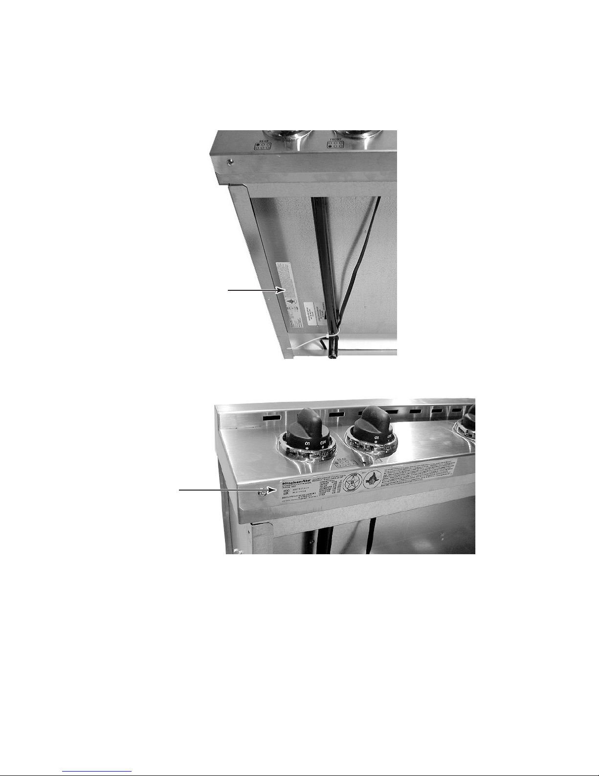
MODEL & SERIAL NUMBER LABEL LOCATION
The Model / Serial Number label is located in one of two positions, as shown below.
Model & Serial
Number Label Location
Prior To July, 2000
Model & Serial
Number Label Location
Beginning July, 2000
- v -

IMPORTANT SAFETY INFORMATION
Your safety and the safety of others is very important.
Important safety messages have been provided in this Job Aid. Always read and obey all
safety messages.
This is the safety alert symbol.
This symbol alerts you to hazards that can kill or hurt you and others.
All safety messages will be preceded by the safety alert symbol and the word
“WARNING.”
All safety messages will identify the hazard, tell you how to reduce the chance of injury, and tell
you what can happen if the instructions are not followed.
- vi -

SPECIFICATIONS
Model Number
Model Description
Size-Configuration
Feature Level/Series
Dimensions/Specifications
Exterior Dimensions
Overall Height (in)
Overall Width (in)
Overall Depth (in)
Cutout Dimensions
Cutout Height (in) (Measure Or Min/Max)
Cutout Width (in) (Measure Or Min/Max)
Cutout Depth (in) (Measure Or Min/Max)
Weight
Net Weight (lbs)
Shipping Weight (lbs)
Ratings
Electric Voltage/Phase/Frequency (Hz)
Circuit Amps
Exterior
Cooktop Controls
Cooktop Control Type
Cooktop Control Location
Cooktop Control #
Control Area
Burner Grate
Griddle
Gas Cooktop Burners
Gas Burner Type
Gas R Front Output (BTU)(Nat/LP)
Gas L Front Output (BTU)(Nat/LP)
Gas R Rear Output (BTU)(Nat/LP)
Gas L Rear Output (BTU)(Nat/LP)
Gas Center Rear Output (BTU)(Nat/LP)
Gas Center Front Output (BTU)(Nat/LP)
Gas Center Right Front (BTU)(Nat/LP)
Gas Center Left Front (BTU)(Nat/LP)
Gas Ignition
LP Conversion
Accessories
Backsplash
Backsplash Part/Comment
Island Trim
Island Trim Part/Comment
Other Accessory
Comment
Miscellaneous
Product Literature
Installation Instructions Part#
Service Manual Part#
Use & Care Guide Part#
Wiring Diagram Part#
Agency Approvals
Approved to Install Over BI Oven
Power Cord Length & # Wires
Warranty
Full
Gas Burners
KGCP467JTL KGCP467JSS KGCP487JSS
Sealed Cooktop Sealed Cooktop Sealed Cooktop
36" Dec. Tile Frames 36" 48"
Professional Professional Professional
7 1/2" 7 1/2" 7 1/2"
35 7/8" 35 7/8" 47 7/8"
26 1/4" 26 1/4" 26 1/4"
7 1/4" 7 1/4" 7 1/4"
36" (F); 35 1/4" (B) 36" (F); 35 1/4" (B) 48" (F); 47 1/4" (B)
1 1/4" (B); 22" (N) 1 1/4" (B); 22" (N) 1 1/4" (B); 22" (N)
140 140 T B D
160 160 T B D
120 V/Single Phase/60 Hz 120 V/Single Phase/60 Hz 120 V/Single Phase/60 Hz
15 Amp 15 Amp 15 Amp
Push-to-Turn Push-to-Turn Push-to-Turn
Infinite Infinite Infinite
Front Front Front
66 8
Yes Yes Yes
Cast Iron Cast Iron Cast Iron
Yes-Opt Yes-Opt Yes-Opt
Yes Yes Yes
Sealed Sealed Sealed
6000 BTU/5000 BTU 6000 BTU/5000 BTU 6000 BTU/5000 BTU
6000 BTU/5000 BTU 6000 BTU/5000 BTU 6000 BTU/5000 BTU
15000 BTU/12000 BTU 15000 BTU/12000 BTU 15000 BTU/12000 BTU
15000 BTU/12000 BTU 15000 BTU/12000 BTU 15000 BTU/12000 BTU
15000 BTU/12000 BTU 15000 BTU/12000 BTU 15000 BTU/12000 BTU
15000 BTU/12000 BTU 15000 BTU/12000 BTU 15000 BTU/12000 BTU
15000 BTU/12000 BTU
15000 BTU/12000 BTU
Electronic Electronic Electronic
Kit Included Kit Included Kit Included
Included Included Included
Standard 9" Standard 9" Standard 9"
Included Included Included
Standard Standard Standard
Yes Yes Yes
Simmer Plate - Factory
Packed
8284670 8284670 8284670
4317318 4317318 4317318
8284642 8284642 8284642
3192100 3192100
AGA,CGA AGA,CGA AGA,CGA
No No No
3 1/2 Foot/3 Wire 3 1/2 Foot/3 Wire 3 1/2 Foot/3 Wire
Yes Yes Yes
12 Mo 12 Mo 12 Mo
60 Mo 60 Mo 60 Mo
Simmer Plate - Factory
Packed
Simmer Plate - Factory
Packed
1-1

— NOTES —
1-2

INSTALLATION HIGHLIGHTS
L.P. GAS CONVERSION
The following parts are provided with Conver-
WARNING
sion Kit Part #8284673:
This conversion kit shall be installed by a
qualified service agency in accordance
with the manufacturer’s instructions and
all applicable codes and requirements of
the authority having jurisdiction. If the
information in these instructions is not
followed exactly, a fire, explosion or production of carbon monoxide may result
causing property damage, personal injury or loss of life. The qualified service
agency is responsible for the proper installation of this kit. The installation is not
proper and complete until the operation
of the converted appliance is checked as
specified in the manufacturer’s instructions supplied with this kit.
WARNING
Orifice/Spud Package
Part #8284663
Conversion Label
Part #8284675
Conversion Instructions - Part #8284674
To convert the cooktop for use with L.P. gas,
perform the following steps.
1. Turn off the gas supply to the cooktop.
2. Disconnect power to the cooktop.
3. Use a screwdriver and remove the access
cap on the gas pressure regulator.
Gas Pressure
Regulator
Access Cap
Explosion Hazard
Securely tighten all gas connections.
If connected to L.P. gas, have a qualified
person make sure gas pressure does not
exceed 14˝ water column.
Examples of a qualified person include
licensed heating personnel, authorized
gas company personnel, and authorized
service personnel.
Failure to do so can result in death, explosion, or fire.
4. Turn the access cap so that the letters L.P.
are facing up and then reinstall the cap on
the regulator.
NAT Position
L.P. Position
2-1
 Loading...