

KitchenAid KAC-24, KBMC140H, KBMC147H, KBHC179J, KBHC109J Technical Education

TECHNICAL EDUCATION
BUILT-IN
MICROWAVE OVEN
KAC-24
JOB AID 4317283

FORWARD
This Job Aid, “KitchenAid Built-In Microwave Oven,” (Part No. 4317283), provides the technician
with information on the installation and service of the KitchenAid Built-In Microwave Oven. It is to
be used as a training Job Aid and Service Manual. For specific information on the model being
serviced, refer to the “Use and Care Guide,” or “Tech Sheet” provided with the microwave oven.
The Wiring Diagrams and Strip Circuits used in this Job Aid are typical and should be used for
training purposes only. Always use the Wiring Diagram supplied with the product when servicing
the unit.
GOALS AND OBJECTIVES
The goal of this Job Aid is to provide detailed information that will enable the service technician to
properly diagnose malfunctions and repair the Built-In Microwave Oven.
The objectives of this Job Aid are to:
• Understand and follow proper safety precautions.
• Successfully troubleshoot and diagnose malfunctions.
• Successfully perform necessary repairs.
• Successfully return the microwave oven to proper operational status.
WHIRLPOOL CORPORATION assumes no responsibility for any repair
made on our products by anyone other than Authorized Factory Service
Technicians.
Copyright 2000, Whirlpool Corporation, Benton Harbor, MI 49022
- ii -

Table of Contents
Page
SPECIFICATIONS .................................................................................................................. 1-1
COMPONENT ACCESS ......................................................................................................... 2-1
Oven Cabinet Component Locations ................................................................................... 2-1
Microwave Oven Component Locations .............................................................................. 2-1
Removing The Microwave Oven Assembly ......................................................................... 2-2
Removing The Oven Control & Display Boards
And The Touch Panel Assembly ....................................................................................... 2-3
Removing The Low Voltage Transformer, The Light Power
Supply, & Suppressor Board ............................................................................................. 2-5
Removing The Blower Motor Assembly ............................................................................... 2-7
Removing The Microwave Oven From The Oven Cabinet .................................................. 2-8
Removing The Primary, Secondary, & Monitor Interlock Switches
And The Air Pressure Relief Valve.................................................................................. 2-10
Removing The Grill Thermal Fuse And The Grill Element Assembly ................................ 2-12
Removing The Convection Temperature Sensor, The Halogen Lamp,
And The Cavity Thermal Fuse ........................................................................................ 2-14
Removing The Convection Thermal Fuse, Convection Element,
And Convection Fan Motor ............................................................................................. 2-16
Removing The Cooling Fan Motor & Air Vent Solenoid ..................................................... 2-18
Removing The Magnetron Thermal Fuse And The Magnetron.......................................... 2-20
Removing The High Voltage Transformer.......................................................................... 2-22
Removing The Line Fuse & Fuseholder, The High Voltage Rectifier,
& High Voltage Capacitor ................................................................................................ 2-24
Removing The Turntable Motor ......................................................................................... 2-26
Removing The Oven Door Handle & Front Door Glass ..................................................... 2-27
Removing The Oven Door & The Inner Glass ................................................................... 2-28
COMPONENT TESTING ........................................................................................................ 3-1
The Turntable & Cooling Fan Motors ................................................................................... 3-1
The Low Voltage Transformer & Light Power Supply .......................................................... 3-2
The Blower & Convection Fan Motors ................................................................................. 3-3
The Convection Temperature Sensor .................................................................................. 3-4
The Cavity, Grill, Convection, & Magnetron Thermal Fuses ................................................ 3-5
The Convection Element & Grill Element Assembly ............................................................ 3-6
The Line Fuse, High Voltage Rectifier, & High Voltage Capacitor ....................................... 3-7
The Air Vent Solenoid & Interlock Switches ......................................................................... 3-8
The High Voltage Transformer & Magnetron ....................................................................... 3-9
Control Panel Resistor ....................................................................................................... 3-10
DIAGNOSIS & TROUBLESHOOTING.................................................................................... 4-1
Failure/Error Display Codes ................................................................................................. 4-1
Components That Can Be Tested At The Control Panel ..................................................... 4-1
Electronic Oven Control Pinouts .......................................................................................... 4-2
Microwave Oven Power Output Test ................................................................................... 4-3
Microwave Oven Relay Logic............................................................................................... 4-3
Troubleshooting Chart.......................................................................................................... 4-4
WIRING DIAGRAMS & STRIP CIRCUITS .............................................................................. 5-1
TECH TIPS ............................................................................................................................. 6-1
- iii -

KITCHENAID MODEL & SERIAL NUMBER DESIGNATIONS
MODEL NUMBER
MODEL NUMBER K B M C 1 4 7 H WH 0
INTERNATIONAL SALES IND.
OR MARKETING CHANNEL
IF PRESENT
PRODUCT GROUP
K = KITCHENAID BRAND
PRODUCT IDENTIFICATION
BH = BUILT-IN HIGH-SPEED OVEN
BM = BUILT-IN MICROWAVE
CM = COUNTERTOP MICROWAVE
HM = MICROWAVE HOOD
MERCHANDISING SCHEME
S = STANDARD
C = MICRO-CONVECTION
CAPACITY / SIZE / SERIES / CONFIGURATION
05 = 0.5 CU FT
08 = 0.8 CU FT
10 = 1.0 CU FT
13 = 1.3 CU FT
14 = 1.4 CU FT
FEATURES
2 = PLUS FEATURES
5 = DELUXE FEATURES
6 = MICRO-CONVECTION
7 = MICRO-CONVECTION WITH SENSOR
S = CARRY-IN WARRANTY (EFFECTIVE 02/96)
X = IN-HOME WARRANTY (EFFECTIVE 02/96)
YEAR OF INTRODUCTION
H = 1999, J = 2000, K = 2001
COLOR CODE
WH = WHITE, BL = BLACK, SS = STAINLESS STEEL
ENGINEERING CHANGE (0, 1, 2, ETC.)
SERIAL NUMBER
SERIAL NUMBER X K 1 6 01004
MANUFACTURING SITE
X = OXFORD
YEAR OF PRODUCTION
K = 2000, L = 2001, M = 2002
WEEK OF PRODUCTION
16TH WEEK
PRODUCT SEQUENCE NUMBER
- iv -

MODEL NUMBER
MODEL NUMBER K BH C 1 7 9 J WH 0
INTERNATIONAL SALES IND.
OR MARKETING CHANNEL
IF PRESENT
PRODUCT GROUP
K = KITCHENAID BRAND
PRODUCT IDENTIFICATION
BH = BUILT-IN HIGH-SPEED OVEN
BM = BUILT-IN MICROWAVE
CM = COUNTERTOP MICROWAVE
HM = MICROWAVE HOOD
MERCHANDISING SCHEME
S = STANDARD
C = MICRO-CONVECTION
CAPACITY / SIZE / SERIES / CONFIGURATION
05 = 0.5 CU FT
08 = 0.8 CU FT
10 = 1.0 CU FT
13 = 1.3 CU FT
17 = 1.4 CU FT
FEATURES
2 = PLUS FEATURES
5 = DELUXE FEATURES
6 = MICRO-CONVECTION
7 = MICRO-CONVECTION WITH SENSOR
9 = MULTIMODE-HI SPEED-CONVECTION
S = CARRY-IN WARRANTY (EFFECTIVE 02/96)
X = IN-HOME WARRANTY (EFFECTIVE 02/96)
YEAR OF INTRODUCTION
H = 1999, J = 2000, K = 2001
COLOR CODE
WH = WHITE, BL = BLACK, SS = STAINLESS STEEL
ENGINEERING CHANGE (0, 1, 2, ETC.)
SERIAL NUMBER
SERIAL NUMBER X K 1 6 01004
MANUFACTURING SITE
X = OXFORD
YEAR OF PRODUCTION
K = 2000, L = 2001, M = 2002
WEEK OF PRODUCTION
16TH WEEK
PRODUCT SEQUENCE NUMBER
- v -
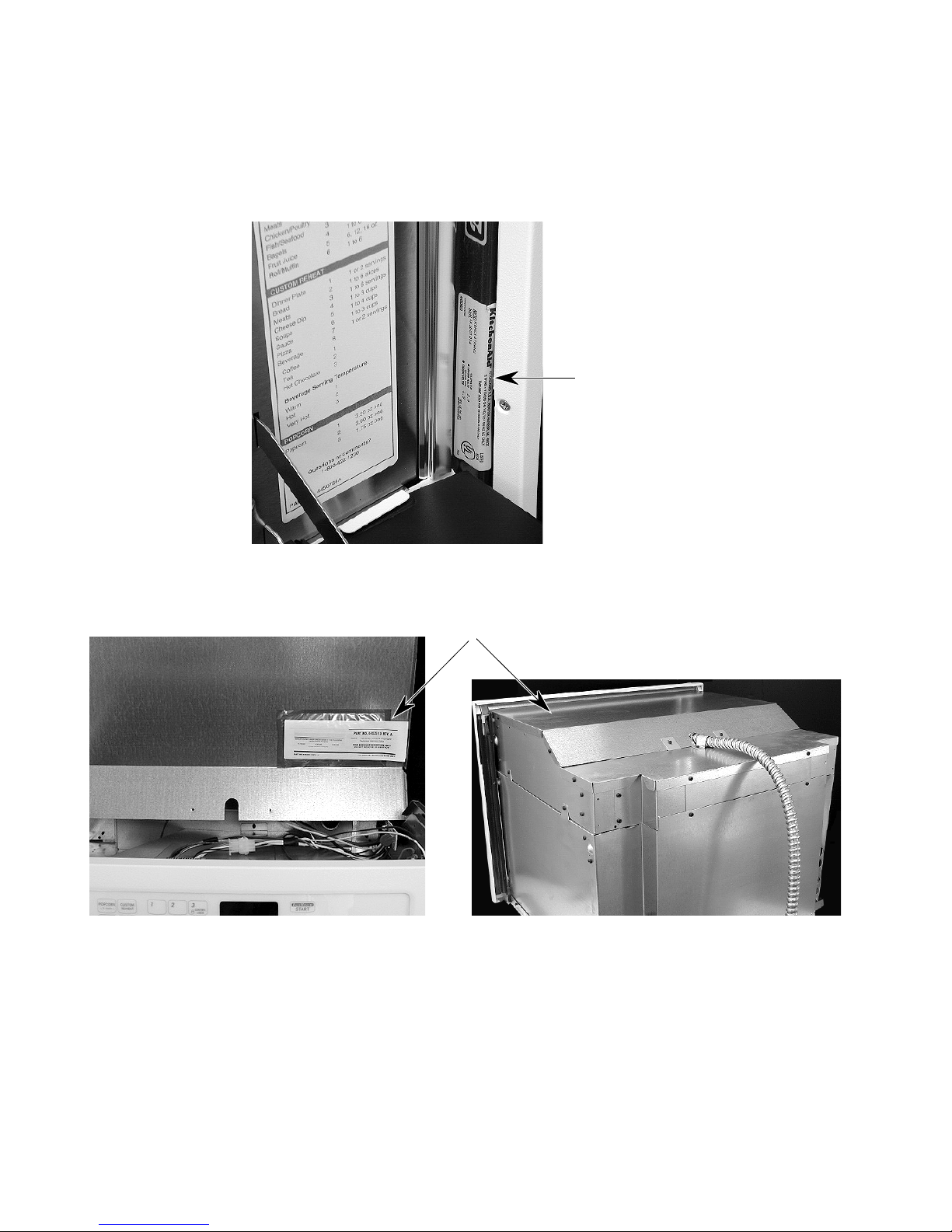
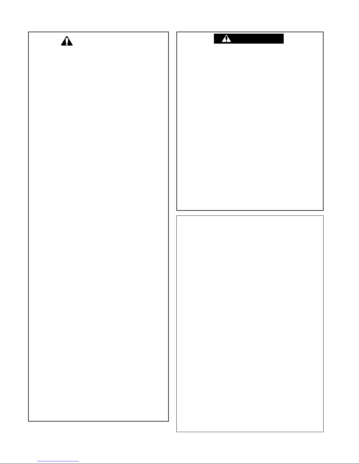
MODEL & SERIAL NUMBER LABEL
AND TECH SHEET LOCATIONS
The Model/Serial Number label and Tech Sheet locations are shown below.
Model & Serial
Number Location
Tech Sheet Location
(Below Top Front Cover)
- vi -

IMPORTANT SAFETY INFORMATION
Your safety and the safety of others is very important.
Important safety messages have been provided in this Job Aid. Always read and obey all safety
messages.
This is the safety alert symbol.
This symbol alerts you to hazards that can kill or hurt you and others.
All safety messages will be preceded by the safety alert symbol and the word
“WARNING.”
All safety messages will identify the hazard, tell you how to reduce the chance of injury, and tell
you what can happen if the instructions are not followed.
Grounding Instructions
CORD CONNECTED
The microwave oven must be grounded. In the event of an electrical short circuit, grounding
reduces the risk of electric shock by providing an escape wire for the electrical current. The
microwave oven is equipped with a cord having a grounding wire with a grounding plug. The plug
must be plugged into an outlet that is properly installed and grounded.
Improper use of the grounding plug can result in a risk of
WARNING
Consult a qualified electrician or serviceman if the grounding instructions are not completely
understood, or if doubt exists as to whether the microwave oven is properly grounded. Do not use
an extension cord. If the power supply cord is too short, have a qualified electrician or serviceman
install an outlet near the microwave oven.
electric shock.
PERMANENTLY CONNECTED
The microwave oven must be connected to a grounded, metallic, permanent wiring system, or an
equipment grounding conductor should be run with the circuit conductors and connected to the
equipment grounding terminal, or lead, on the microwave oven.
- vii -

Warning To Service Technicians
To avoid possible exposure to microwave radiation or energy, visually check the oven for damage
to the door and door seal before operating any oven. Use a microwave survey meter to check the
amount of leakage before servicing. In the event the R.F. Ieakage exceeds 4 mw/cm
appropriate repair must be made before continuing to service the unit. Check interlock function by
operating the door latch. The oven cook cycle should cut off before the door can be opened.
The door and latching assembly contains the radio frequency energy within the oven. The door is
protected by three safety interlock switches. Do not attempt to defeat them.
UNDER NO CIRCUMSTANCES SHOULD YOU TRY TO OPERATE THE OVEN WITH THE
DOOR OPEN.
• Proper operation of microwave ovens requires that the magnetron be properly assembled to
the waveguide and cavity. Never operate the magnetron unless it is properly installed.
• Be sure the “RF” seal is not damaged and is assembled around the magnetron dome properly
when installing the magnetron.
• Routine service safety procedures should be exercised at all times.
• Untrained personnel should not attempt service without a thorough review of test procedures
and safety information contained in this Job Aid.
KitchenAid microwave ovens have a monitoring system designed to assure proper operation of the
safety interlock systems.
2
at 5 cm,
The interlock monitor switch will immediately cause the oven fuse to blow if the door is opened and
the primary door interlock switch and/or the secondary interlock switch contacts fail in a closed
position.
CAUTION: REPLACE BLOWN FUSE WITH 20 AMPERE CLASS H FUSE ONLY
Test the upper and lower door interlock switches, cook relay and interlock monitor switch (middle
switch) for proper operation as described in the component test procedures, before replacing the
blown oven fuse.
DO NOT ATTEMPT TO REPAIR STICKING CONTACTS OF ANY INTERLOCK SWITCH,
SAFETY SWITCH OR COOK (LATCH) RELAY. THE COMPONENTS MUST BE REPLACED.
Any indication of sticking contacts during component tests requires replacement of that component
to assure reliability of the safety interlock system.
IF THE FUSE IS BLOWN, THE MONITOR, PRIMARY, AND SECONDARY INTERLOCK
SWITCHES MUST BE REPLACED. BE SURE THEY ARE PROPERLY CONNECTED.
- viii -

Precautions To Be Observed Before And During
Servicing To Avoid Possible Exposure
To Excessive Microwave Energy
1. Do not operate or allow the oven to be operated with the door open.
2. Make the following safety checks on all ovens to be serviced before activating the magnetron
or other microwave source and make repairs as necessary.
a) Interlock Operation
b) Proper Door Closing
c) Seal and Sealing Surfaces (Arcing, Wear and Other Damage)
d) Damage to or Loosening of Hinges and Latches
e) Evidence of Dropping or Abuse
3. Before turning on the microwave power for any service test or inspection within the microwave
generating components, check the magnetron, wave guide or transmission line and cavity for
proper alignment.
4. Any defective or misadjusted components in the interlock, monitor, door seal and microwave
generation and transmission system shall be repaired by procedures described in the Job Aid
for the specific microwave oven being serviced before the oven is released to the owner.
5. A microwave leakage check to verify compliance with Federal Performance Standards should
be performed on each oven prior to release to the owner.
6. Do not attempt to operate the oven if the door glass is broken.
- ix -
CAUTION
• High voltages are present during the cook
cycle. Extreme caution should be observed at all times.
• Abrasive cleansers, steel-wool pads, gritty
wash cloths, etc. can damage the control
panel and the interior and exterior oven
surfaces. Use a sponge with mild detergent or paper towels with spray glass
cleaner. Apply spray glass cleaner to paper towel. Do not spray directly on oven.
• Before touching any oven component or
wiring, always unplug the oven from its
power source and discharge the capacitor by using a 20,000 ohm discharge
resistor or use an insulated plastic handle
screwdriver to short across the capacitor
terminals.
• Check that the unit is grounded before
troubleshooting. Be careful of the high
voltage circuits. Discharge any static
charge from your body by touching ground
before handling any part of the circuitry on
the control board. Electrostatic discharge
may damage the control circuit.
• Do not touch oven components or wiring
during operation. Attach meter leads with
alligator clips when making operational
tests.
• For continued protection against radiation emission, replace only with these
types of switches: Primary (Interlock)
Switch: SZM-V16-FA-63 or VP-533A-OF;
Secondary (Interlock) Switch: SZM-V01FA-32; Interlock (Monitor) Switch: SZMVI6-FA-62 or VP-532A-OF; Oven Lamp
Switch: SZM-V6-FA-31 or VP-331 A-OD.
• It is neither necessary nor advisable to
attempt measurement of high voltage.
• Attaching the adaptor ground terminal to
the wall receptacle cover screw does not
ground the appliance unless the cover
screw is metal and not insulated and the
wall receptacle is grounded through the
house wiring.
WARNING
• Disconnect the oven from electrical supply before servicing. Failure to do so could
result in electrical shock or death.
• Improper use of the grounding plug can
result in a risk of electrical shock. Do not,
under any circumstance, cut or remove
the third ground prong from the power
cord plug.
Fire, Electrical Shock, Excessive
Exposure to Microwave Energy,
Personal Injury & Product
Damage Hazard
• Do not block the rear air intake openings
or exhaust vents. Allow a few inches of
space at the back of the oven where
intake openings and exhaust vents are
located. Blocking the air intake openings
and exhaust vents can cause damage to
the oven and poor cooking results.
Electrostatic Discharge (ESD)
Sensitive Electronics
ESD problems are present everywhere. ESD
may damage or weaken the electronic control assembly. The new control assembly
may appear to work well after repair is finished, but failure may occur at a later date
due to ESD stress.
• Use an antistatic wrist strap. Connect
wrist strap to green ground connection
point or unpainted metal in the appliance, or touch your finger repeatedly to
a green ground connection point or unpainted metal in the appliance.
• Before removing the part from its package, touch the antistatic bag to a green
ground connection point or unpainted
metal in the appliance.
• Avoid touching electronic parts or terminal contacts; handle electronic control assembly by the edges only.
• When repackaging failed electronic control assembly in antistatic bag, observe
above instructions.
- x -

R.F. LEAKAGE TEST
EQUIPMENT
• Electromagnetic energy leakage monitor
(NARDA 81 00B, HOLADAY H 1 501 ).
• 250 ml glass beaker.
TEST
On every service call, checks for microwave
energy emission must be made according to
the following manner.
1. Remove the cooking rack from the oven
cavity, if the microwave oven is so
equipped.
2. Place a 250 ML (8.0 oz.) glass of water in
the center of the oven bottom.
3. Select "HIGH" cook power, turn the micro-
wave oven on, and test for R.F. Ieakage at
the following locations using the pattern
shown below:
a) Around the cabinet at the front.
b) Around the door.
c) Across the console panel.
d) Horizontally across the door.
e) Vertically across the door.
f) Diagonally across the door.
g) Across the air vents.
h) Across the rear air vent.
i) All lockseams.
j) Weld at bottom.
k) Bottom plate.
I) Oven feet.
NOTE: Enter leakage readings in space BEFORE and AFTER on the service document.
All microwave ovens exceeding the emission
2
level of 4 mw/cm
must be reported to Dept. of
Service for microwave ovens immediately and
the owner should be told not to use the microwave oven until it has been repaired completely.
If a microwave oven is found to operate with the
door open, report to Dept. of Service, the
manufacturer and CDRH* immediately. Also
tell the owner not to use the oven.
The interlock monitor switch acts as the final
safety switch protecting the customer from
microwave radiation. If the interlock monitor
switch operated to blow the fuse when the
interlocks failed, you must replace all interlock
switches with new ones, because the contacts
of those interlock switches may be melted and
welded together.
All repairs must be performed in such a manner
that microwave energy emissions are minimal.
Address for CDRH is:
Office of Compliance (HFZ-312) Center
for Devices and Radiological Health
1390 Piccard Drive
Rockville, Maryland 20850
* CDRH: Center for Device and Radiological Health,
Food and Drug Administration.
4. The scan speed is one inch per second.
When checking for R.F. Ieakage, use an approved R.F. measuring device to assure less
than 4 mw/cm2 emission at 5 cm distance with
a maximum scan rate of 2.5 cm/second, in
compliance with U.S. Government Department
of Health, Education and Welfare 21 CFR1030,
performance Standard for Microwave Ovens.
A properly operating door and seal assembly
will normally register small emissions, but they
must be no greater than 4 mw/cm2 to allow for
measurement uncertainty.
- xi -

— NOTES —
- xii -

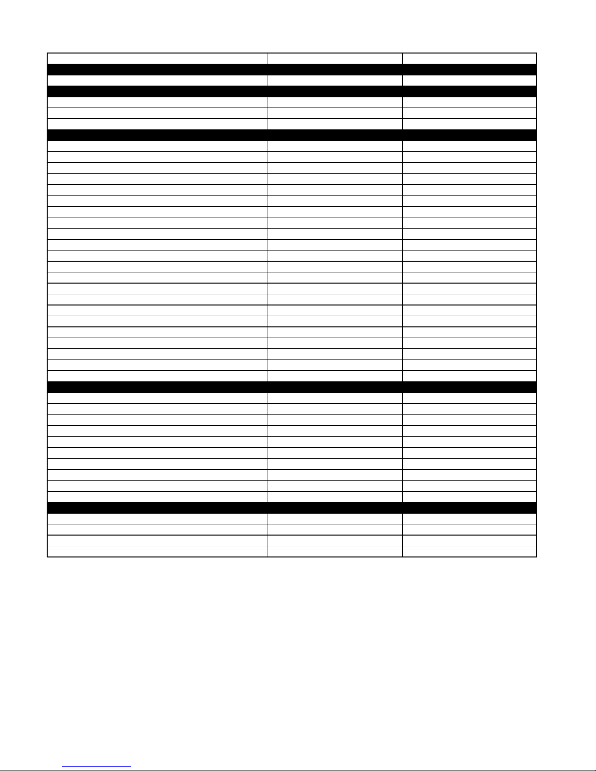
SPECIFICATIONS
Model Number
Release Info
Model Description
Size-Configuration
Feature Level/Series
Dimensions/Specifications
Exterior Dimensions
Overall Height (in)
Overall Width (in)
Cutout Height (in) (Measure Or Min/Max)
Cutout Width (in) (Measure Or Min/Max)
Cutout Depth (in) (Measure Or Min/Max)
Other Dimensions
Conduit Size (in) (Length/Diameter)
Total Connected Load in kW
240 Volts
208 Volts
Circuit Amps
Exterior
Oven Control Type
Microwave Controls
Membrane Touch
Probe
Microwave Timer
Diagnostics
Error Indication
MW Power (Watts)
Off/Cancel
Programming Tone
Staged Cooking # Levels/Type
Start/Enter
Stoppable Turntable
Broil Element Output (Watts)
Broil Heat-Up Time
Crisp Turntable Performance # IEC Pts/Min for Release
Crisp Pan Size/Type
MW Cavity Volume (cu ft)
MW Cavity Material
Miscellaneous
Product Literature
Installation Instructions Part/Comment
Tech Sheet Part/Comment
Use & Care Guide Microwave Part/Comment
Other
Agency Approvals
Installation Hardware
Residential Use Only
Warranty
Full (Months)
Extended
Electronic Controls (Months)
Electrical Elements (Months)
Magnetron (Months)
KBMC140H KBMC147H
Built In Microwave Built In Microwave
30" 27"
Crisp Convection Crisp Convection
20 1/2" 20 1/2"
29 3/4" 26 3/4"
19 7/16" 19 7/16"
28 1/2" 25 1/2"
23 1/4" 23 1/4"
57"; 1/2" 57"; 1/2"
3 kw 3 kw
3 kw 3 kw
20 AMP 20 AMP
Electronic Electronic
VFD (Blue,Green,Red) VFD (Blue,Green,Red)
Yes Yes
No No
Yes Yes
Yes Yes
Yes Yes
900 Watts 900 Watts
Yes Yes
Yes Yes
3 Level 3 Level
Yes Yes
No No
1200 Watts 1200 Watts
<1 minute <1 minute
3.5 3.5
322 mm OD 322 mm OD
1.4 1.4
Stainless Stainless
4452615 4452615
4452613 4452613
4452614 4452614
Cooking Tips - 3191638 Cooking Tips - 3191638
UL & CSA UL & CSA
Yes Yes
Yes Yes
12 12
60 60
60 60
60 60
1-1
Model Number KBHC179J KBHC109J
Release Info
Colors Black, White, Stainless, Biscuit Black, White, Stainless, Biscuit
Model
Model Description Built-In High Speed Built-In High Speed
Size-Configuration 27" 30"
Feature Level/Series Crisp Convection Crisp Convection
Dimensions/Specifications
Exterior Dimensions
Overall Height (in) 20 1/2" 20 1/2"
Overall Width (in) 26 3/4" 29 3/4"
Overall Depth Inc Hrdwr/Hndl (in) 25 1/8" 25 1/8"
Depth W/O Handle (in) 23 7/8" 23 7/8"
Other Dimensions
Conduit Size (in) (Length/Diameter) 57"; 1/2" 57"; 1/2"
Weight
Net Weight (lbs) 110 117
Total Connected Load in kW
240 Volts 4.4 kw 4.4 kw
208 Volts 3.8 kw 3.8 kw
Circuit Amps 30 Amp 30 Amp
Probe No No
Microwave Timer Yes Yes
Diagnostics Yes Yes
Error Indication Yes Yes
MW Power (Watts) 900 Watts 900 Watts
Stoppable Turntable No No
Broil Element Type Quartz Quartz
Broil Element Output (Watts) 1200 Watts 1200 Watts
Broil Heat-Up Time <1 minute <1 minute
Interior
MW Cavity Volume (cu ft) 1.4 1.4
MW Cavity Material Porcelain Enamel Steel Porcelain Enamel Steel
Other
Agency Approvals UL UL
Residential Use Only Yes Yes
Warranty
Full (Months) 12 12
Electronic Controls (Months) 60 60
Electrical Elements (Months) 60 60
Magnetron (Months) 60 60
Miscellaneous
Installation Instructions Yes Yes
Installation Instructions Part 4452615 4452615
Tech Sheet Part 4452613 4452613
Use & Care Guide Microwave Part 4452614 4452614
1-2

COMPONENT ACCESS
This section instructs you on how to service each component inside the Model KBMC147H BuiltIn Microwave Oven. The components and their locations are shown below.
OVEN CABINET COMPONENT LOCATIONS
Blower Motor
Suppressor Board
Light Power Supply
Oven Control &
Display Boards
MICROWAVE OVEN COMPONENT LOCATIONS
Convection
Temperature
Sensor
Air Pressure
Relief Valve &
Secondary
Interlock Switch
Convection Fan Motor
Convection Element
Halogen Lamp
Convection
Thermal Fuse
Thermal Fuse
Low Voltage
Transformer
High Voltage Rectifier
Line Fuse
Cavity
High Voltage
Capacitor
High Voltage
Transformer
Magnetron
Mag. Thermal Fuse
Air Vent
Solenoid
Primary
Interlock Switch
Monitor
Interlock Switch
Cooling Fan
Motor
Grill Element
Assembly
Turntable
Motor
2-1
Grill
Thermal Fuse

REMOVING THE MICROWAVE OVEN ASSEMBLY
WARNING
WARNING
Electrical Shock Hazard
Disconnect power before servicing.
Replace all panels before operating.
Failure to do so could result in death or
electrical shock.
CAUTION: When you work on the microwave
oven, be careful when handling the sheet metal
parts. Sharp edges may be present, and you
can cut yourself if you are not careful.
5. To remove the side trim, pull the bottom
out approximately 2˝ and slide the top
down to disengage it from the front panel.
Slide Down
Side Trim
1. Disconnect the electrical power to the
microwave oven.
2. Remove the glass turntable and roller
assembly from inside the oven cavity.
Turntable &
Roller Assembly
3. Completely open the microwave oven door.
4. Remove the screws from the side trim.
Pull Out
6. Remove the two cabinet mounting screws.
Cabinet Mounting
Screw (1 On Each
Side)
Side Trim Screw
(1 On Each Side)
Excessive Weight Hazard
Use two or more people to remove and
reinstall the microwave oven.
Failure to follow this instruction can result in
back, or other injury.
7. Slide the microwave oven out of its mounting location.
2-2

REMOVING THE OVEN CONTROL & DISPLAY BOARDS
AND THE TOUCH PANEL ASSEMBLY
4. To remove the oven control panel, pull it
WARNING
Electrical Shock Hazard
out at the bottom, and lift and unhook it
from the oven cabinet support at the top.
Disconnect power before servicing.
Replace all panels before operating.
Failure to do so could result in death or
electrical shock.
CAUTION: When you work on the microwave
oven, be careful when handling the sheet metal
parts. Sharp edges may be present, and you
can cut yourself if you are not careful.
1. Disconnect the electrical power to the
microwave oven.
2. Pull the microwave oven assembly forward several inches so that you can access the sides of the front panel (see page
2-2 for the side trim and mounting screw
removal procedure).
3. Remove the screws from the oven control
panel.
Oven
Control
Panel
Lift Off
Top
Support
Pull Out
5. Pull the ground clip on the end of the green
wire from the edge of the metal panel, and
disconnect the wire connectors from the
board. Set the panel face down on a
padded surface to protect the finish.
Ground Clip
Oven Control Panel Screw
(1 On Each Side)
Wire Connectors
Continued on the next page.
2-3

6. To remove the oven control & display
boards:
a) Remove the seven mounting screws.
b) Lift the ends of the locking arm and
disconnect the ribbon cable from its
connector.
NOTE: The control and display boards are
designed to be replaced as an assembly.
Lift Ends Of
Locking Arm
Screws
7. To remove the touch panel assembly:
a) Remove the standoffs and spacers from
over the mounting studs.
Touch Panel
Assembly
Standoffs & Spacers
Mounting Screws
b) Remove the six mounting screws.
c) Lift the touch panel assembly off the
front of the oven cabinet.
REASSEMBLY NOTE: When you reinstall the
oven control panel, use the following procedure (refer to the photos on the previous page,
as necessary):
Screws
1. Reconnect the wiring to the control board
terminals.
2. Clip the ground wire to the metal edge of
the control panel.
3. Hook the ends of the control panel over
the rubber tips of the brackets.
4. Push the bottom of the control panel in and
position the plastic air duct
under the lip of
the panel.
Air Duct
Bottom Lip Of Control Panel
5. Align the mounting holes and install the
two side screws in the control panel.
2-4

REMOVING THE LOW VOLTAGE TRANSFORMER,
THE LIGHT POWER SUPPLY, & SUPPRESSOR BOARD
5. To remove the low voltage transformer:
WARNING
Electrical Shock Hazard
Disconnect power before servicing.
Replace all panels before operating.
Failure to do so could result in death or
electrical shock.
CAUTION: When you work on the microwave
oven, be careful when handling the sheet metal
parts. Sharp edges may be present, and you
can cut yourself if you are not careful.
1. Disconnect the electrical power to the
microwave oven.
2. Remove the microwave oven assembly
from its mounting location (see page 2-2
for the procedure).
3. Remove the screw from the power conduit
clamp and remove the clamp.
4. Remove the 10 screws from the top front
and top rear oven cabinet covers.
a) Disconnect the 10-hole connector from
the control board at P17.
b) Remove the mounting screw at the top
and unhook the bottom transformer tab
from the oven cabinet slot.
Screw LV Transformer Connector P17
6. To remove the light power supply:
a) Disconnect the four wires from the LINE
and LOAD terminals. Note that the LINE
terminals are smaller than the LOAD
terminals to prevent miswiring.
b) Remove the mounting screw and un-
hook the tab from the oven cabinet slot.
Conduit
Clamp
Top Front Cover
(4 Screws)
Line & Load
Wires
Top Rear Cover
(6 Screws)
Screw
Light Power
Supply
Continued on the next page.
2-5

7. To remove the suppressor board:
a) Remove the hex nuts from the black
and white wires and remove the wires
from the screw terminals.
b) Remove the mounting screw holding
the suppressor board to the terminal
strip.
Suppressor Board
White Wires Black Wires
Screw
2-6
 Loading...