

KitchenAid GAS RANGE Installation Instructions Manual
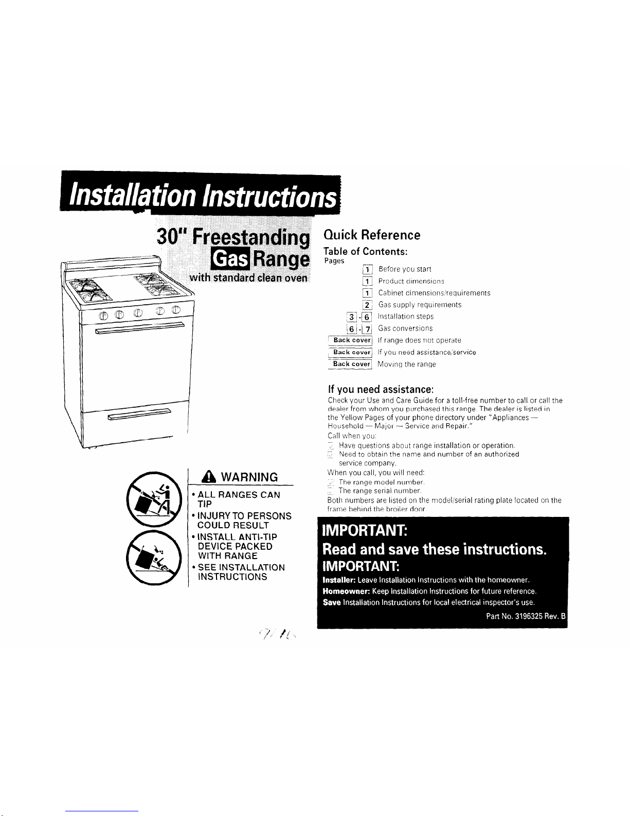
A WARNING
l
ALL RANGES CAN
TIP
l
INJURY TO PERSONS
COULD RESULT
l
INSTALL ANTI-TIP
DEVICE PACKED
WITH RANGE
l
SEE INSTALLATION
INSTRUCTIONS
Reference
Contents:
m Before you start
q
1 Product dimensions
m Cabinet dimensions/requirements
z Gas supply requrrements
a -(61 Installation steps
m-j Gas conversions
‘Back1 If range does not operate
;v If you need assistance,‘service
Back Moving the range
If you need assistance:
Check your Use and Care Guide for a toil-free number to call or call the
dealer from whom you purchased this range. The dealer is listed in
the Yellow Pages of your phone directory under “Appliances Household - Major - ‘Service and Repair.”
Call when you:
:I Have questions about range installation or operation
2 Need to obtain the name and number of an authorized
service company.
When you call, you will need:
;,-. The range model number.
z The range serial number.
Both numbers are listed on the model/serial rating plate located on the
frame behind the broiler door.
Important: Observe all governing codes
and ordinances.
This installation must conform with
all local
codes and ordinances. In the absence of local
codes, installation must conform with American
National Standard, National Fuel Gas Code ANSI
2223.1 - latest edition**.
Proper installation is your responsibility. A
qualified technician must install this range. Make
sure you have everything necessary for correct
installation. It is the installer’s responsibility to
comply with installation clearances specified on
the gas information label. The gas information
label and model/serial rating plate are located on
the frame behind the broiler door.
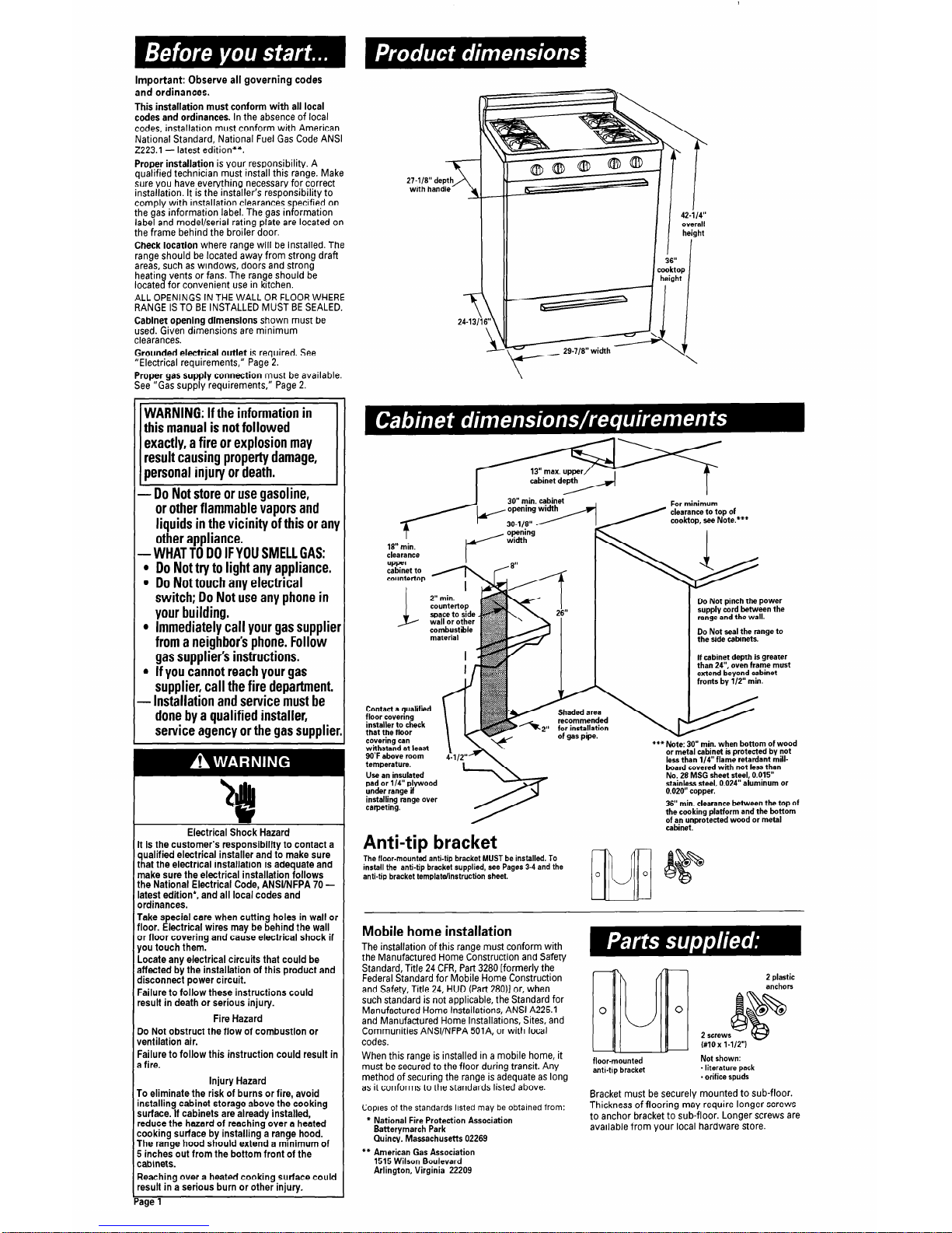
Check location where range will be installed. The
range should be located away from strong draft
areas, such as windows, doors and strong
heating vents or fans. The range should be
located for convenient use in kitchen.
ALL OPENINGS IN THE WALL OR FLOOR WHERE
RANGE IS TO BE INSTALLED MUST BE SEALED.
Cabinet opening dimensions shown must be
used. Given dimensions are minimum
clearances.
Grounded electrical outlet is required. See
“Electrical requirements,” Page 2.
Proper gas supply connection must be available.
See “Gas supply requirements,” Page 2.
24-13116”
3
i
42-i14"
overall
height
36”
cooktop
height
I
WARNING: If the information in
this manual is not followed
exactly, a fire or explosion may
result causing property damage,
personal injury or death.
- Do Not store or use gasoline,
or other flammable vapors and
liquids in the vicinity of this or any
other aooliance.
ia”
min.
-WHAT id DO IFYOU SMELL GAS:
l
Do Not try to light any appliance.
l
Do Not touch any electrical
switch; Do Not use any phone in
your building.
l
Immediately call your gas supplier
from a neighbor’s phone. Follow
gas supplier’s instructions.
l
If you cannot reach your gas
supplier, call the fire department.
- Installation and service must be
done by a qualified installer,
service agency or the gas supplier.
Do Not pinch the power
supply cord between the
range and the wall.
Do Not seal the range to
the side cabinets.
If cabinet depth is greater
than 24”, oven frame must
extend beyond cabinet
fronts by l/2” min.
Contact a qualified
floor covering
installer to check
that the floor
covering can
withstand at least
9O’F above room
temperature.
Use an insulated
pad or l/4” plywood
under range if
installing range over
carpeting.
Shaded area
recommended
for installation
-1 --- -I--
1
***Note: 30” min. when bottom of wood
or metal cabinet is protected by not
less than l/4” flame retardant mill-
board covered with not less than
No 28 MSG sheet steel, 0.015”
stainless steel, 0.024” aluminum or
0.020” copper.
36” min. clearance between the top of
the cooking platform and the bottom
of an unprotected wood or metal
Electrical Shock Hazard
It is the customer’s responsibility to contact a
qualified electrical installer and to make sure
that the electrical installation is adequate and
make sure the electrical installation follows
the National Electrical Code, ANSUNFPA 70 latest edition*, and all local codes and
ordinances.
Take special care when cutting holes in wall or
floor. Electrical wires may be behind the wall
or floor covering and cause electrical shock if
you touch them.
Locate any electrical circuits that could be
affected by the installation of this product and
disconnect power circuit.
Failure to follow these instructions could
result in death or serious injury.
Fire Hazard
Do Not obstruct the flow of combustion or
ventilation air.
Failure to follow this instruction could result in
a fire.
Injury Hazard
To eliminate the risk of burns or fire, avoid
installing cabinet storage above the cooking
surface. If cabinets are already installed,
reduce the hazard of reaching over a heated
cooking surface by installing a range hood.
The range hood should extend a minimum of
5 inches out from the bottom front of the
cabinets.
Reaching over a heated cooking surface could
result in a serious burn or other injury.
Anti-tip bracket
-
The floor-mou& anti-tip bracket MUST be installed. To
install the anti-tip bracket supplied, see Pages 3-4 and the
anti-tip bracket templatelinstruction sheet.
Mobile home installation
The installation of this range must conform with
the Manufactured Home Construction and Safety
2 plastic
anchors
Standard, Title 24 CFR, Part 3280 [formerly the
Federal Standard for Mobile Home Construction
and Safety, Title 24, HUD (Part 28011 or, when
such standard is not applicable, the Standard for
Manufactured Home Installations, ANSI A225.1
and Manufactured Home Installations, Sites, and
Communities ANSI/NFPA 501A, or with local
codes.
When this range is installed in a mobile home, it
i
must be secured to the floor during transit. Any
floor-m01
unted
method of securing the range is adequate as long
anti-tip bracket
0
L
2 screws
(#10x l-1/2")
Not shown:
- literature pack
* orifice spuds
as it conforms to the standards listed above.
Bracket must be securely mounted to sub-floor.
Copies of the standards listed may be obtained from:
* National Fire Protection Association
Batterymarch Park
Thickness of flooring may require longer screws
to anchor bracket to sub-floor. Longer screws are
available from your local hardware store.
Quincj, Massachusetts 02269
** American Gas Association
1515 Wilson Boulevard
Arlington, Virginia 22209
‘age
1
- A.G.A. design-certified flexible metal
connector
(4-5 feet) or rigid gas supply line as needed
- Insulated pad or l/4” plywood if range is installed
over carpeting
combination
wrench
wood floor:
l/8” drill bit
concrete/ceramic floors:
3/16” carbide-tipped masonry
drill bit (Hammer may be
needed for anchors.)
tape measure
or ruler
d
Fire Hazard
Range must be connected to a regulated gas
supply.
Gas supply must NOT exceed 1 Cinch water
column pressure. This must be checked by a
qualified technician before installing the
range.
Do Not use an open flame to test for leaks
from gas connections.
New A.G.A. design-certified flexible gas line
should be used when local codes permit.
Failure to follow these instructions could
result in a fire or injury.
Observe all governing codes and ordinances.
This installation must conform with all local
codes and ordinances. In the absence of local
codes, installation must conform with American
National Standard, National Fuel Gas Code ANSI
2223.1 - latest edition**.
Input ratings shown on the model/serial rating
plate are for elevations up to 2,000 feet. For
assistance when installing the range at higher
elevations, contact your local service company.
Type of gas: This range is design-certified by the
American Gas Association (A.G.A.) for Natural or
L.P. gases with appropriate conversion. (See
“Gas conversions” instructions, Pages 6-7.) The
model/serial rating plate (located on the frame
behind the broiler door) has information on the
type of gas that can be used. If the type of gas
listed does not agree with the type of gas
available, check with the local gas supplier.
Conversion must be done by a qualified service
technician.
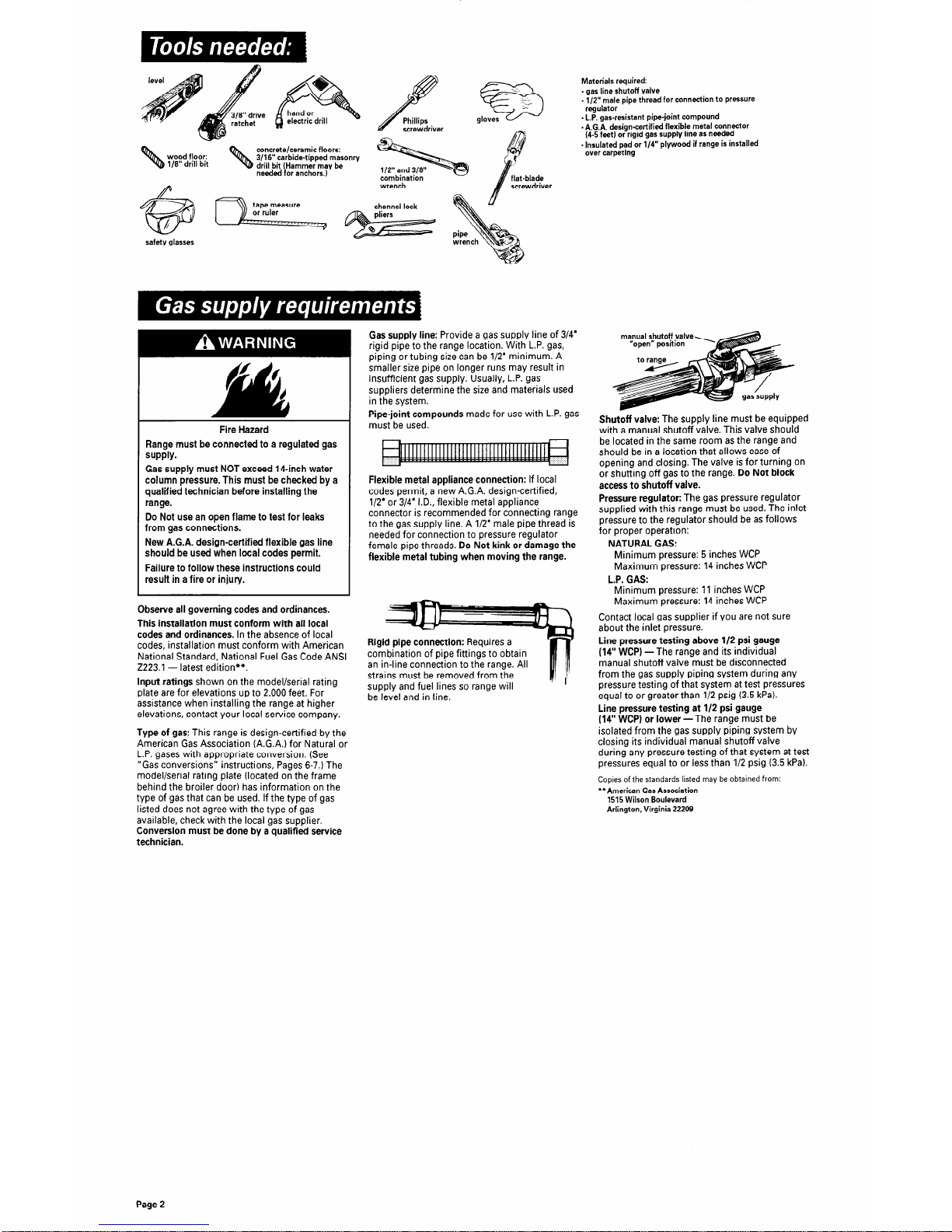
Gas supply line: Provide a gas supply line of 3/4’
rigid pipe to the range location. With L.P. gas,
piping or tubing size can be l/2’ minimum. A
smaller size pipe on longer runs may result in
insufficient gas supply. Usually, L.P. gas
suppliers determine the size and materials used
in the system.
Pipe-joint compounds made for use with L.P. gas
must be used.
Flexible metal appliance connection: If local
codes permit, a new A.G.A. design-certified,
l/2’ or 3/4’ I.D., flexible metal appliance
connector is recommended for connecting range
to the gas supply line. A l/2’ male pipe thread is
needed for connection to pressure regulator
female pipe threads. Do Not kink or damage the
flexible metal tubing when moving the range.
rpe fittings to obtain
strains must be removed from the
supply and fuel lines so range will
be level and in line.
manual shutoff valve
Shutoff valve: The supply line must be equipped
with a manual shutoff valve. This valve should
be located in the same room as the range and
should be in a location that allows ease of
opening and closing. The valve is for turning on
or shutting off gas to the range. Do Not block
access to shutoff valve.
Pressure regulator: The gas pressure regulator
supplied with this range must be used. The inlet
pressure to the regulator should be as follows
for proper operation:
NATURAL GAS:
Minimum pressure: 5 inches WCP
Maximum pressure: 14 inches WCP
L.P. GAS:
Minimum pressure: 11 inches WCP
Maximum pressure: 14 inches WCP
Contact local gas supplier if you are not sure
about the inlet pressure.
Line pressure testing above l/2 psi gauge
(14” WCP) -The range and its individual
manual shutoff valve must be disconnected
from the gas supply piping system during any
pressure testing of that system at test pressures
equal to or greater than l/2 psig (3.5 kPa).
Line pressure testing at l/2 psi gauge
(14” WCPI or lower -The range must be
isolated from the gas supply piping system by
closing its individual manual shutoff valve
during any pressure testing of that system at test
pressures equal to or less than l/2 psig (3.5 kPa).
Copies of the standards listed may be obtained from:
**American Gas Association
1515 Wilson Boulevard
Arlington, Virginia 22209
Page 2
 Loading...