

Page 1
TECHNICAL EDUCATION
KAR-8
25 cu. ft. TOP-MOUNT
REFRIGERATOR/FREEZER
G-MODEL
JOB AID 4322312
I
Page 2

INTRODUCTION
This Job Aid, 1998 "G" Model, 25 cu. ft. TOP-MOUNT REFRIGERATOR/FREEZERS, (Part No.
4322312) provides specific information for the installation, service and repair of 1998 "G" Model 25 cu.
ft. Top Mount Refrigerator/Freezers.
1998 "G" Model, 25 cu. ft. T0P-MOUNT REFRIGERATOR/FREEZERS has been compiled to provide
the most recent information on design, features, troubleshooting, service and repair procedures.
Whirlpool-required sweep charge procedures are to be strictly adhered to when repairing the sealed
system. For a complete explanation of those procedures, refer to the Job Aid, SWEEP CHARGE
PROCEDURES FOR THE 90's, (Part No. 4321717) and its companion video (Part No. 4321718.)
GOALS AND OBJECTIVES
The goal of this Job Aid is to provide detailed information that will enable the service technician to
properly diagnose malfunctions and repair 1998 "G" Model 25 cu. ft. Top-Mount Refrigerator/Freezers.
The objectives of the Job Aid are:
The service technician will -
• Understand proper safety precautions.
• Follow proper refrigerant recovery procedures.
• Successfully troubleshoot and diagnose malfunctions.
• Successfully perform necessary repairs.
• Successfully return the refrigerator/freezer to proper operational status.
TO THE INSTRUCTOR/INDEPENDENT STUDENT
At the end of certain sections of this Job Aid you will find a "Confirmation of Learning Exercise." A
pencil will be necessary to complete these exercises. Certain exercises may require that service
procedures be performed if an appropriate appliance is available.
Inc.Inc.
Inc.
Inc.Inc.
For the way it's made.™
II
Page 3

TABLE OF CONTENTS
INTRODUCTION ..................................................................................... II
TABLE OF CONTENTS ......................................................................... III
SAFETY ......................................................................................................... IV
R134a REFRIGERANT SERVICE INFORMATION ......................................... V
SECTION ONE
INSTALLATION CONSIDERATIONSINSTALLATION CONSIDERATIONS
INSTALLATION CONSIDERATIONS
INSTALLATION CONSIDERATIONSINSTALLATION CONSIDERATIONS
SECTION TWO
THEORY OF OPERATIONTHEORY OF OPERATION
THEORY OF OPERATION
THEORY OF OPERATIONTHEORY OF OPERATION
Temperature Control....................................................................................3
Refrigerant Flow ..........................................................................................3
Air Flow ......................................................................................................... 4
Defrost System .............................................................................................5
SECTION THREE
COMPONENT ACCESSCOMPONENT ACCESS
COMPONENT ACCESS
COMPONENT ACCESSCOMPONENT ACCESS
..............................................
....................... 1
..............................................
Accessing the Component Compartment .................................................7
Accessing the Heat Exchanger and Wiring Harness ................................8
Accessing Components in the Freezer Compartment .............................8
Accessing Component in the Refrigerator Compartment .....................12
SECTION FOUR
DIAGNOSIS AND TROUBLESHOOTINGDIAGNOSIS AND TROUBLESHOOTING
DIAGNOSIS AND TROUBLESHOOTING
DIAGNOSIS AND TROUBLESHOOTINGDIAGNOSIS AND TROUBLESHOOTING
Troubleshooting Guide..............................................................................15
Diagnostic Information ..............................................................................17
SECTION FIVE
TECH TIPSTECH TIPS
TECH TIPS
TECH TIPSTECH TIPS
Typical External Sweat Patterns ...............................................................19
Wiring Harness Schematic ........................................................................20
Wiring Diagram .......................................................................................... 21
Strip Circuits ..............................................................................................22
Serial and Model Number Designators ....................................................24
KitchenAid Warranty .................................................................................. 25
III
Page 4
SAFETY
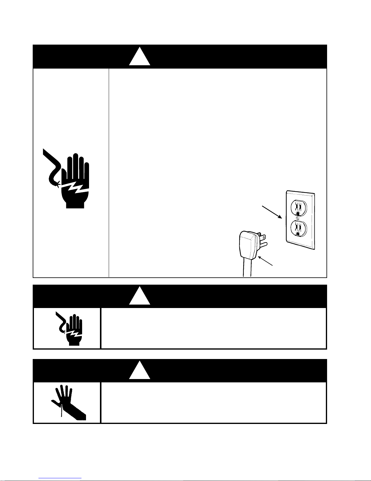
! WARNING
To avoid the risk of electrical shock,
property damage, personal injury or death:
• The power cord must be plugged into a 3-prong, grounding-type
wall receptacle, grounded in accordance with the National Electrical
Code, ANSI/NFPA 70 - latest edition and local codes and
ordinances.
• It is the personal responsibility of the consumer to have a proper
3-prong wall receptacle installed by a qualified electrician.
• DO NOT, UNDER ANY CIRCUMSTANCES, REMOVE THE
POWER CORD GROUNDING PRONG.
• A separate adequately fused and grounded circuit should be
available for this appliance.
• Do not remove any grounding wires
from individual components while
servicing, unless the component is
to be removed and replaced. It is
extremely important to replace all
grounding wires when components
are replaced.
Grounding Type
Wall Receptacle
Power Supply Cord
with 3-Prong
Grounding Plug
Disconnect the electrical power before servicing any components .
This unit has several sharp edges in areas where you will be working to
remove components for service. Wear protective gloves where sharp
! WARNING
ELECTRIC SHOCK HAZARD
Failure to do so can result in death or electrical shock.
! WARNING
PERSONAL INJURY HAZARD
edges are present.
IV
Page 5
R134a REFRIGERANT
Service Information
This product uses R134a refrigerant. This refrigerant requires synthetic Ester oil in the compressor.
This cooling system does not tolerate contamination from any of the following:
• Other Refrigerants
• Moisture
• Petroleum-based Lubricants
• Silicone Lubricants
• Cleaning Compounds
• Rust Inhibitors
• Leak Detection Dyes
• Any Other Type of Additive
As a result the following precautions should be observed:
• Use equipment dedicated to R134a sealed system service only.
• Do not leave a replacement compressor open to the atmosphere for more than 10 minutes.
• Always replace the filter-drier when performing any repairs on the sealed system.
• USE ONLY R134a REFRIGERANT FOR BACKFLUSHING AND SWEEP PROCEDURES.
• If the rubber plugs on the service replacement compressor appear to have been tampered
with or removed, DO NOT USE THE COMPRESSOR. Get another one.
• The filter-drier MUST be cut from the sealed system. Never unbraze the filter-drier from
system tubing. Applying heat will drive moisture back into the sealed system.
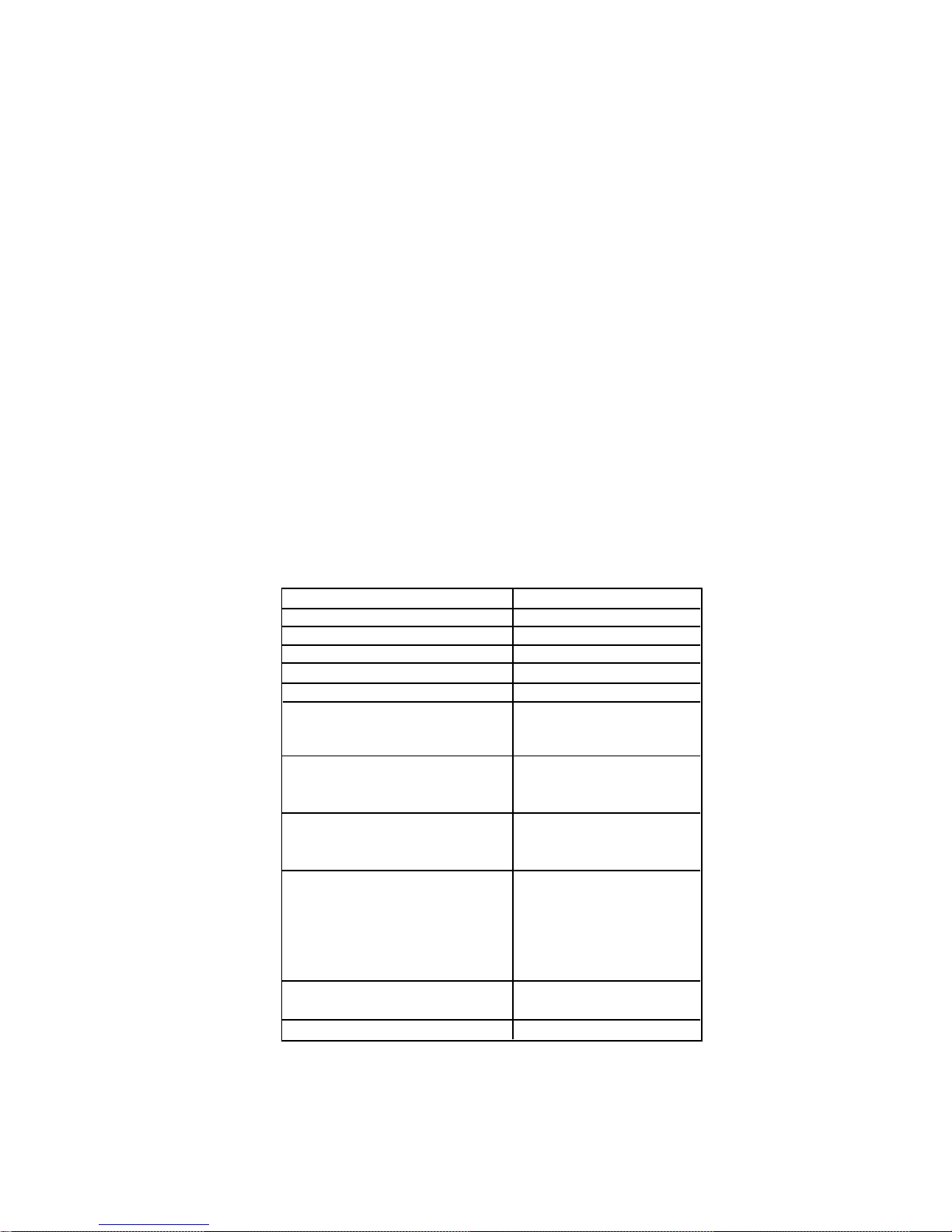
HEALTH AND SAFETY HANDLING
Allowable Overall Exposure Limit
Vapor Exposure to Skin
Liquid Exposure to Skin
Vapor Exposure to Eyes
Liquid Exposure to Eyes
Above Minimum Exposure Limit
Safety and Handling
Spill Management
Fire and Explosion Hazards
Storage Conditions
Disposal Procedure
R134a
1,000 ppm
No effect
Can cause frostbite
Very slight irritation
Can cause frostbite
Can cause asphyxiation,
tachycardia and cardiac
arrhythmias.
Wear appropriate skin and
eye protection. Use adequate
ventilation.
Remove or Extinguish Ignition
or Combustible Sources.
Evacuate or Ventilate Area.
May decompose if contact is
made with flames and heating
elements. Container may
explode if heated due to
pressure rise. combustion
products are toxic.
The procedures / rules for R12
also apply to R134a.
Reclaim
SEE SWEEP CHARGE PROCEDURES FOR THE 90's,
Part No. 4321717 FOR COMPLETE INSTRUCTIONS ON
SERVICING THE SEALED SYSTEM.
V
Page 6

VI
Page 7
ANSWER SHEET
CONFIRMATION OF LEARNINGCONFIRMATION OF LEARNING
CONFIRMATION OF LEARNING
CONFIRMATION OF LEARNINGCONFIRMATION OF LEARNING
EXERCISESEXERCISES
EXERCISES
EXERCISESEXERCISES
Section One
True or False Statements:
F
1. ___
F
2. ___
T
3. ___
T
4. ___
5. ___
T
Section One
Label the Components:
Section Two
True or False Statements:
T
1. ___
F
2. ___
F
3. ___
T
4. ___
T
5. ___
Section Three
True or False Statements:
F
1. ___
T
2. ___
T
3. ___
F
4. ___
F
5. ___
Evaporator
Evaporator
Outlet
Capillary Tube
Heat
Loop
Compressor
Condenser
Process
Tube
Filter Dryer
Condenser
Outlet
VII
Page 8

VIII
Page 9

IX
Page 10
SECTION TWO
THEORY OF OPERATIONTHEORY OF OPERATION
THEORY OF OPERATION
THEORY OF OPERATIONTHEORY OF OPERATION
TEMPERATURE CONTROL
Freezer temperature is regulated by an air-sensing thermostat inside the control box located at the top
front of the refrigerator compartment. This thermostat actuates the compressor to circulate refrigerant
through the sealed system to remove heat from the freezer and refrigerator sections. The thermostat
should be set to maintain 0° - 5°F freezer food temperature.
Refrigerator temperature is regulated by an automatic air damper control. The air damper control is a
thermostat that manually actuates the air damper door. This control governs the amount of refrigerated
air entering the refrigerator compartment. The control should be set to maintain 38°F to 40°F fresh
food temperature.
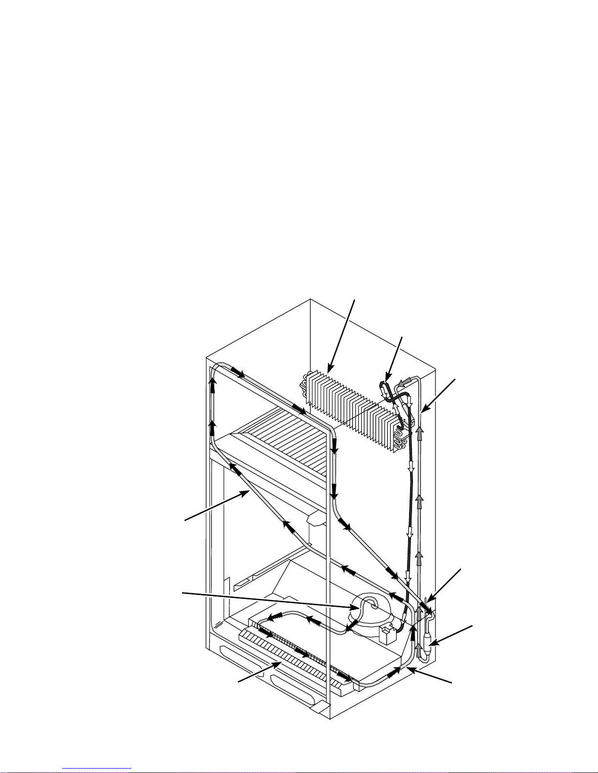
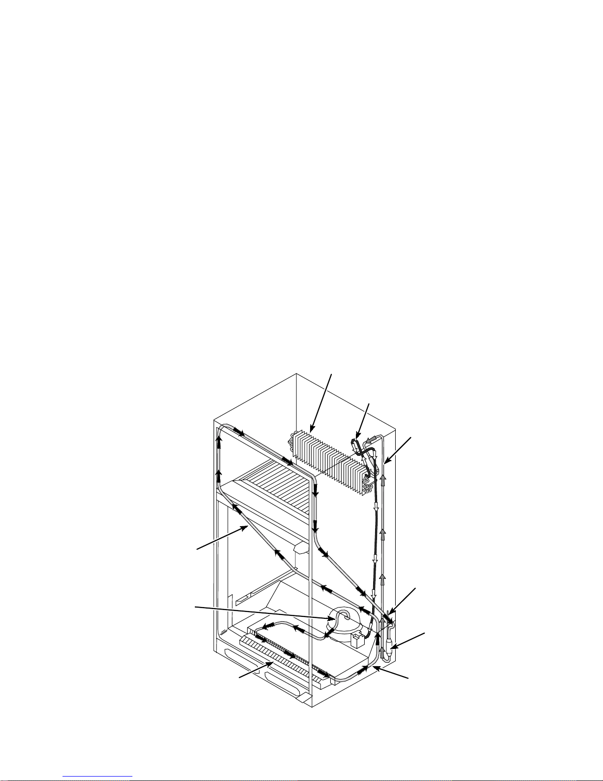
Refrigerant Flow
Refrigerant is pumped from the compressor and passes through the condenser, the heat loop around
the freezer compartment opening, the filter drier, capillary tube, evaporator and the suction line back to
the compressor.
The heat loop is made of a continuous piece of copper tubing with no brazed joints.
Evaporator
Evaporator Outlet
Capillary
Tube
Heat
Process
Compressor
Tube
Filter Drier
Condenser
Condenser
Outlet
Fig. 2
3
Page 11
Air Flow
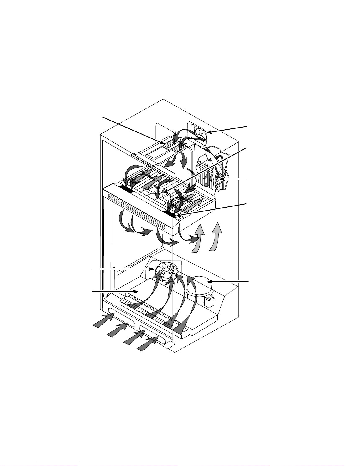
Air inside the freezer section is cooled when it is drawn across the evaporator and circulated through
the freezer compartment.
Cold freezer air is also drawn into the refrigerator compartment and circulated to remove heat.
Freezer Air
Supply Grille
Evaporator Fan
Assembly
Refrigerator Air
Supply Duct
Evaporator
Freezer Return Air
Through Bottom of
Freezer Floor
Condenser Fan
Condenser
Compressor
Fig. 3
4
Page 12
Defrost System
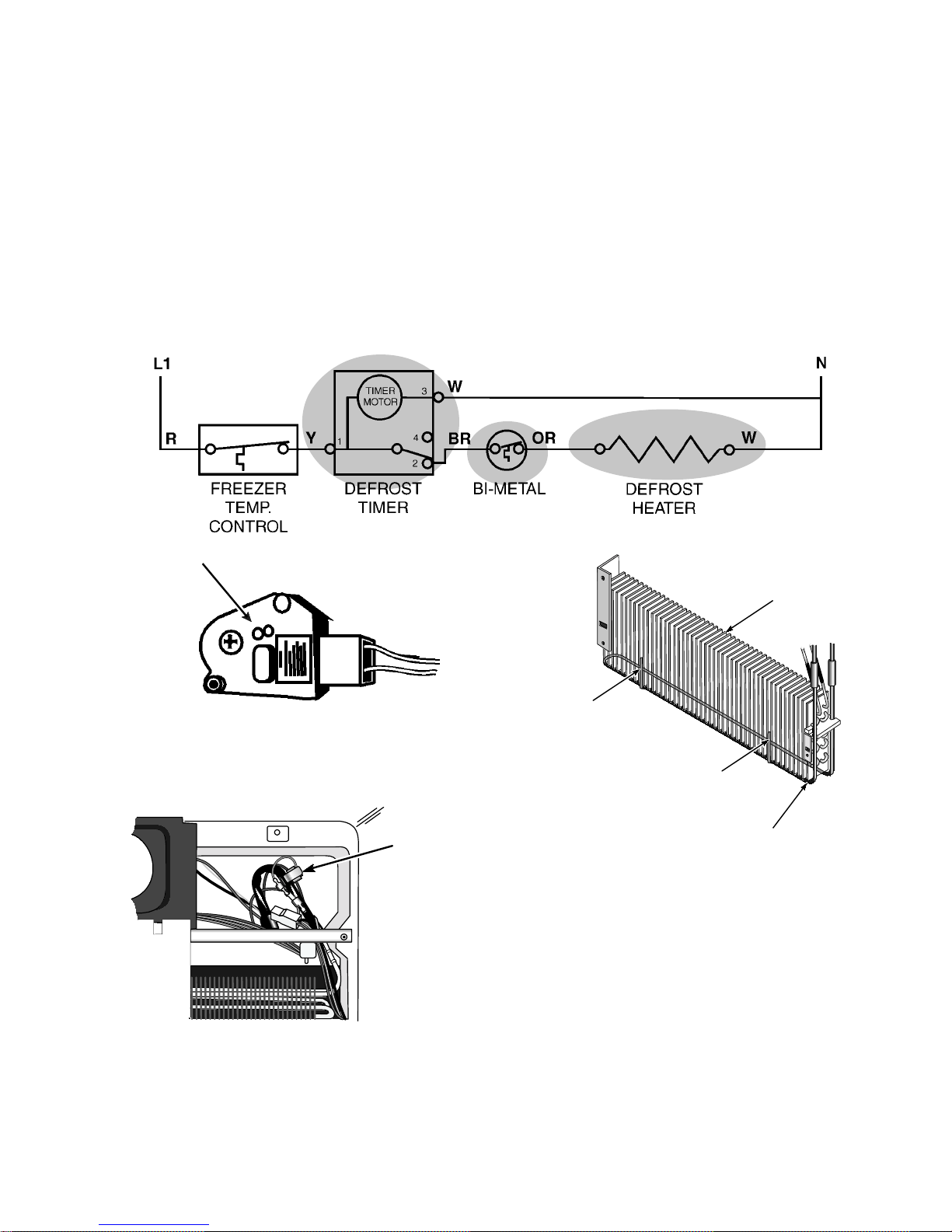
Automatic defrost after every eight hours of compressor run time is accomplished by utilizing a defrost
timer thermostat in the control box, a defrost bi-metal thermostat attached to the outlet of the evapotator
and a radiant electric heater suspended beneath the evaporator. (Fig. 4)
The bi-metal thermostat is attached to the outlet side of the evaorator coil tubing (Fig. 7) and opens at
48°F to terminate the defrost heating. About 33 minutes from the start of the defrost cycle, the timer
restores operation to the compressor circuit. (Fig. 5) The bi-metal thermostat contacts close at 13°F,
enabling the defrost heater to operate during the next defrost cycle.
The defrost heater is suspended on the right side and across the bottom of the evaporator. The defrost
heater also provides warming to the defrost drain area to keep it clear during the defrost cycle.(Fig.6)
Defrost Timer
Fig.5
Bi-Metal
Thermostat
Fig.4
Evaporator
Retaining
Clip
Retaining
Clip
Defrost Heater
Fig.6
Fig.7
5
Page 13
SECTION TWO
CONFIRMATION OF LEARNINGCONFIRMATION OF LEARNING
CONFIRMATION OF LEARNING
CONFIRMATION OF LEARNINGCONFIRMATION OF LEARNING
EXERCISESEXERCISES
EXERCISES
EXERCISESEXERCISES
In the blank to the left of the statement, place a T if the statement is TRUE or an F if the statement
is FALSE.
___1. This refrigerator/freezer is provided with a refrigerant heat loop that is foamed in place
around the freezer compartment door.
___ 2. Air flow from the freezer compartment to the refrigerator compartment is regulated through
a motorized air damper door.
___ 3. The defrost timer is located inside the freezer compartment control box.
___ 4. The defrost cycle is designed to occur after eight hours of compressor run-time.
___ 5. The defrost bi-metal thermostat is designed to open at 48°F and close at 13°F.
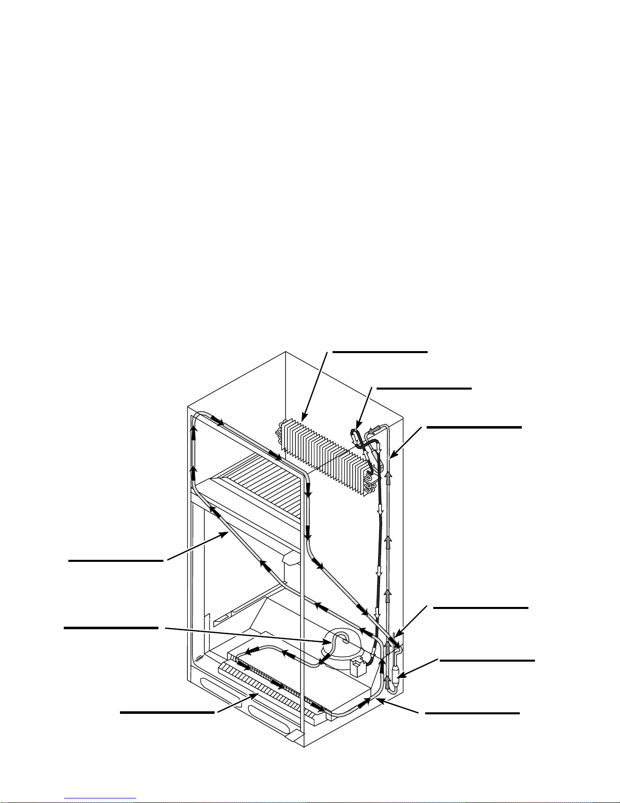
Label all of the components in the illustration below.
6
Page 14
SECTION THREE
COMPONENT ACCESSCOMPONENT ACCESS
COMPONENT ACCESS
COMPONENT ACCESSCOMPONENT ACCESS
Accessing the components in the 25 cu. ft. Top-Mount Refrigerator/Freezer is generally quite similar to
other typical Whirlpool units.
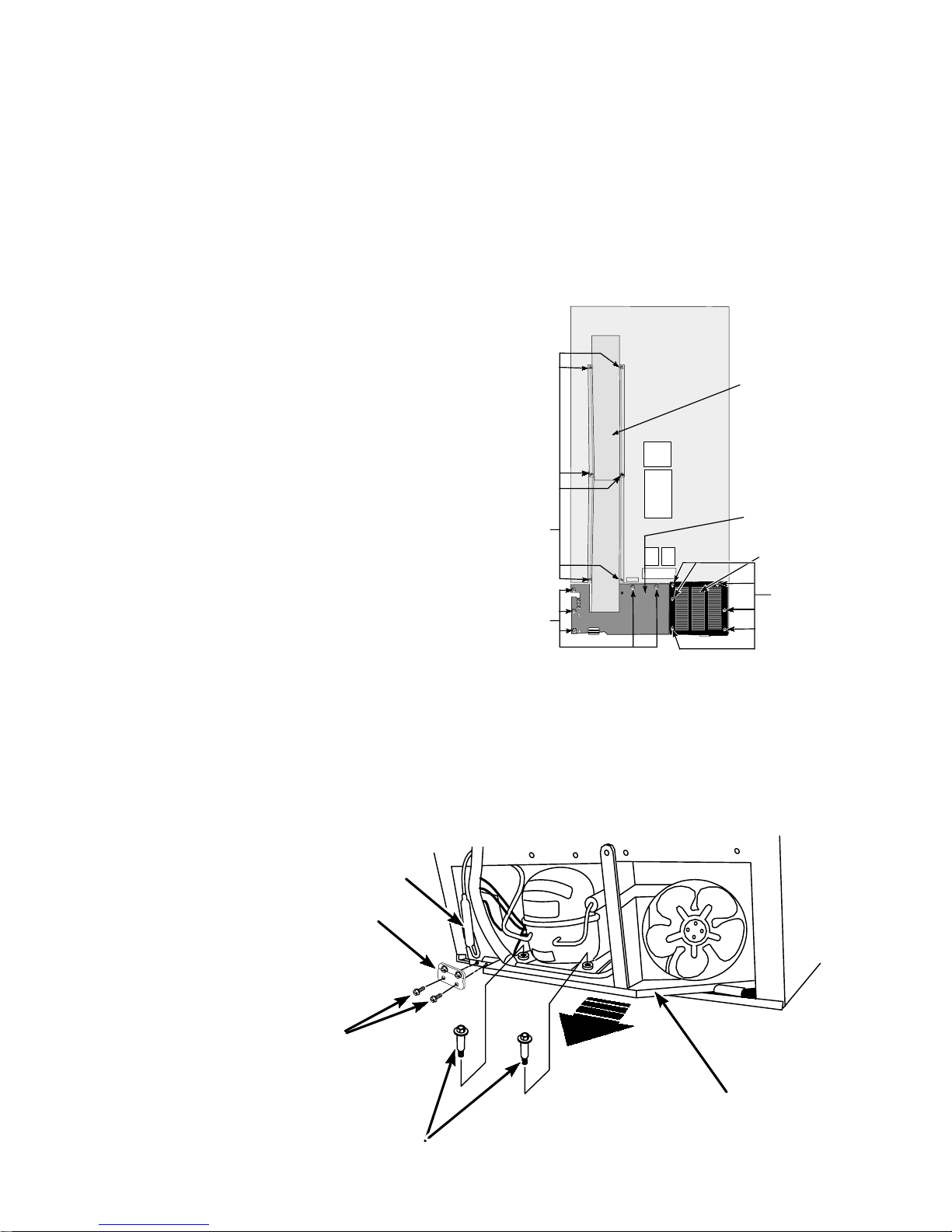
Accessing the Component Compartment
Components located in the component compartment are assembled on a slide-out tray at the bottom of
the unit. The compressor, filter-drier, condenser, condenser fan and water supply valve are located in
this area. To gain access to these components the compartment, heat exchanger and condenser fan
covers must be removed and the tray slid out.
1. Remove the six (6) hex-head screws
securing the condenser fan cover to the
cabinet. (Fig. 8-A)
2. Remove the six (6) screws securing the
two sections of the heat exchanger cover
to the back of the unit. (Fig. 8-B)
3. Remove the five (5) screws securing the
component compartment cover to the
cabinet. (Fig. 8-C)
4. Remove the two (2) screws securing the
water supply valve to the base rail. (Fig.
8) NOTE: If a water supply valve is mount-
ed on the bracket, it is not necessary to
disconnect the copper supply tubing or the
plastic supply tubing.
(B)
Hex-
Head
Screws
(C)
Hex-
Head
Screws
Fig. 17
Fig. 8
Heat
Exchanger
Cover
Compartment
Cover
Condenser Fan
Cover
(A)
Hex-
Head
Screws
5. Push the filter-drier out of its retaining bracket and gently move it out of the way. NOTE: Take
care not to kink any of the tubing connected to the filter-drier.
6. Remove the two (2) compressor mounting bolts securing the slide-out tray to the lower rear
cabinet rail. (Fig. 9)
7. Carefully slide the tray out from the unit. (Fig. 9) NOTE: The tray can only slide out a few
inches without kinking the tubing. To slide the tray completely out, the sealed system must be
purged and the tubing disconnected.
Filter-Drier
Water Supply Valve
Mounting Bracket
Screws
PULL
OUT
Slide-Out
Tray
Compressor
Mounting Bolts
Fig. 9
7
Page 15
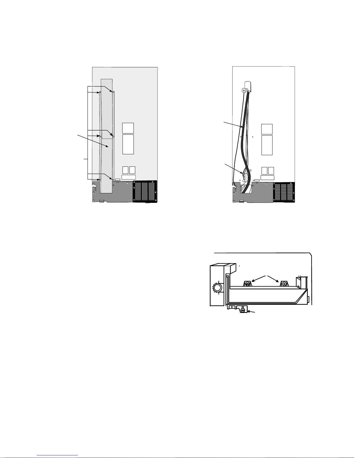
Accessing the Heat Exchanger and Wiring Harness
The heat exchanger and wiring harness are located under the metal cover on the back of the cabinet.
Remove the six (6) screws securing the cover to the back of the cabinet. (Fig. 10 & 11)
Heat
Exchanger
Heat
Exchanger
Cover
Screws
Fig. 17
Fig. 10 Fig. 11
Wiring
Harness
Accessing Component in the Freezer Section
The evaporator, automatic ice maker, and other associated components are all accessible inside the
freezer section.
Removing the Automatic Ice Maker
NOTE: If Ice-Maker needs replacing, use FSP Replacement
Ice Maker.
1. Remove the hex-head screw securing the bottom
bracket to the freezer liner.
2. Loosen the two (2) screws in the slotted brackets at
the top of the automatic ice maker three or four
turns. (These screws must be removed if the
evaporator cover is to be removed.) (Fig. 12)
3. Slide the automatic ice maker up and off the screws.
LOOSEN
THESE SCREWS
REMOVE
THIS SCREW
Fig. 12
4. Disconnect the automatic ice maker wiring harness connector and remove the automatic ice
maker from the unit.
5. Remove the extension from the water inlet tube.
Servicing the Evaporator and Other Related Components
The evaporator, evaporator fan, defrost bi-metal and defrost heater are located behind the
evaporator cover.
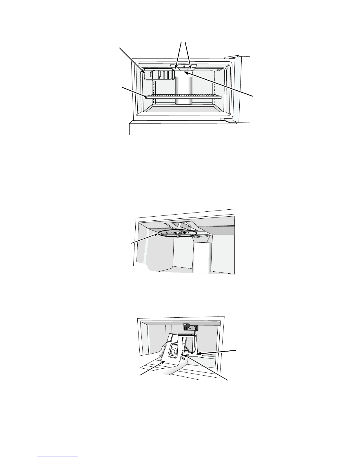
1. Remove freezer shelf and two (2) screws securing each shelf bracket to the back wall of
the freezer compartment. (Fig. 13)
8
Page 16
Screws (under lens)
Ice Cube Tray
Shelf
Freezer
Shelf
Light Lens
Screw
Fig. 13
2. Remove the automatic ice maker (if present) or slide the ice cube tray shelf forward to release
it from the (3) stand-off screws securing it to the freezer compartment ceiling.
3. Remove screw securing the rear of the light lens.
4. Remove the two (2) screws securing the freezer ceiling air duct to the top of the freezer
compartment.
5. Pull the air duct down from the freezer compartment ceiling. Take care not to break the five (5)
clips securing the front of the air duct to the ceiling. (Fig. 14)
5
Clips
Fig. 14
6. Disconnect the electrical wire to the light switch and light socket and remove the air duct. the
wiring harness will remain attached to a piece of insulating material, which can be moved out of
the way when removing the evaporator cover. (Fig. 15)
Insulation
Air Duct
Fig. 15
Light Fixture
Wires
7. Remove the remaining screws securing the evaporator cover to the back wall of the freezer
compartment.
9
Page 17
Removing the Evaporator Fan Motor
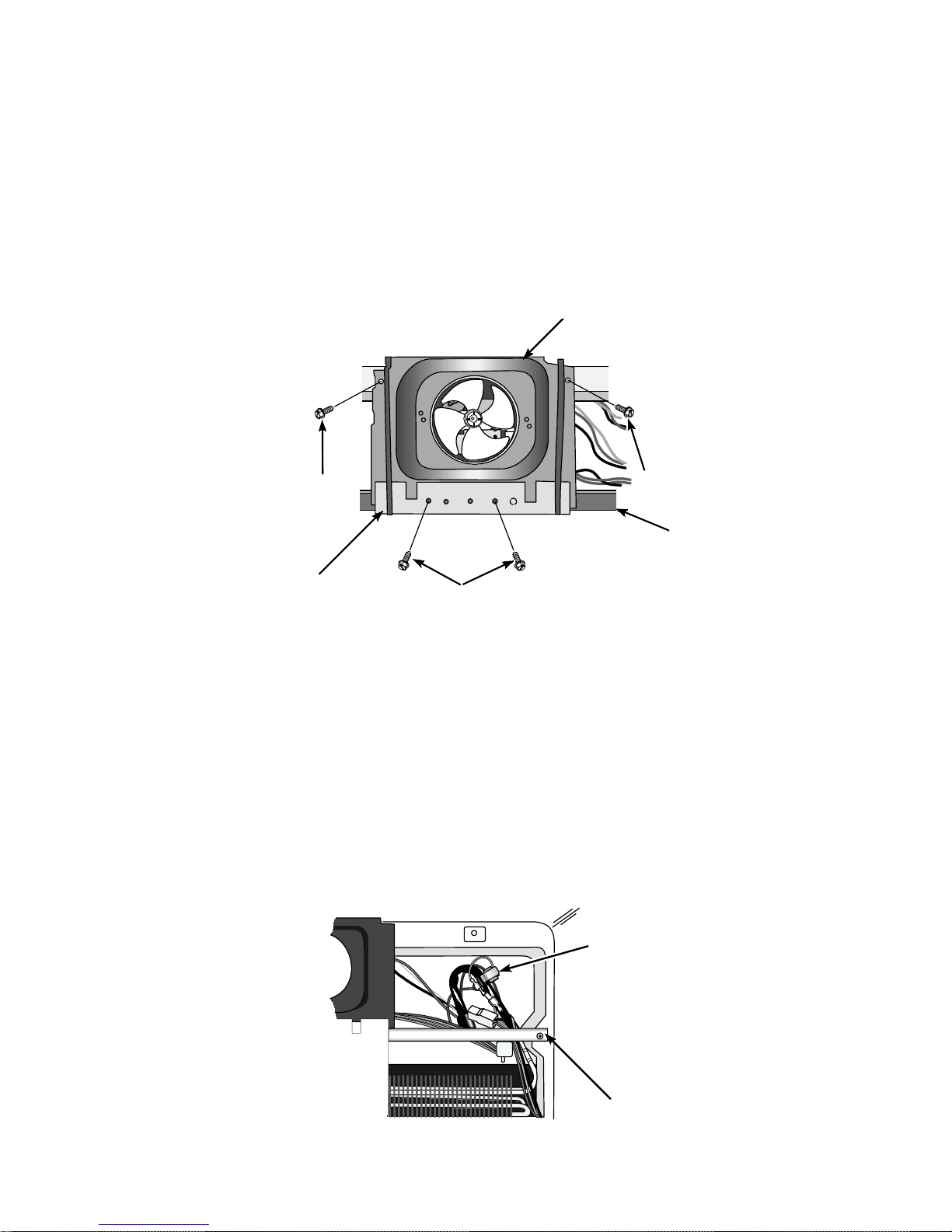
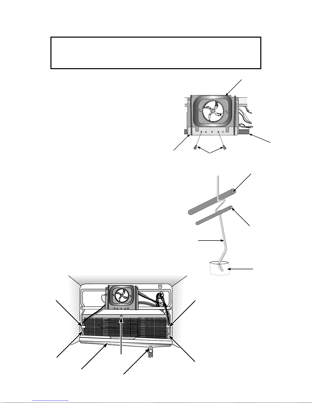
The evaporator fan motor is mounted on a bracket that is attached to a shroud mounted to the back
wall of the freezer section. (Fig. 16)
1. Remove freezer back panels.
2. Remove the two screws mounting the sheet metal cover plate to the bottom of the fan shroud.
3. Remove the two screws mounting the top of the fan shroud to the cabinet.
4. Lay the fan motor and the shroud over and remove wiring.
5. Remove the two screws mounting the bracket
Fan Shroud
to the motor.
Screw
Cover Plate
Screws
Screw
Center
Support
Bracket
Fig. 16
Servicing the Evaporator, Defrost Bi-metal and Defrost Heater
The evaporator, defrost bi-metal and defrost heater are serviceable parts on these units.
Removing the Defrost Bi-metal
1. Remove the freezer back panel.
2. Unclip the thermostat from evaporator coil outlet tube and remove thermostat. (Fig. 17)
3. Cut either the red and blue leads or the blue and gray leads depending on which thermostat to
be removed.
4. When installing a replacement defrost bi-metal, use wire nuts to reconnect the pigtail wires of
the defrost bi-metal to the bare wire harness leads.
Fig.17
10
Bi-Metal
Thermostat
Center
Support
Bracket
Page 18
Removing the Defrost Heater Element
NOTE: Using this procedure will require the use of a ¼” magnetic nut driver when
removing and installing the three (3) screws securing the evaporator heat
shield. A dropped screw will fall into the condensate drain trough and
possibly be lost into the condensate drain.
1. Remove the freezer back panel.
2. Remove the two (2) screws securing the
cover plate to the bottom of the fan shroud.
(Fig. 18)
3. Remove the center support bracket.
4. Remove the drain tube heat sink. (Fig. 19)
5. Disconnect the wire leads to the heater element.
6. Carefully remove the styorfoam air blocks
from each side of the evaporator. (Fig. 20)
7. Carefully remove the three screws securing
Cover
Plate
the heat shield to the back wall. (Fig. 20)
8. Carefully lift the evaporator and heat shield
assembly up over the rear lip of the freezer
floor and pull it away from the back wall.
The evaporator can now be detached from
the heat shield hangers and clips.
Screws
Fan Shroud
Center
Support
Bracket
Fig.18
Evaporator
Tubing
Air
Block
Heat
Shield
Screw
Drain
Trough
Fig. 20
Drain
Heater
Rod
Heat
Sink
Condensate
Drain
Fig. 19
Air
Block
Heat
Shield
Screw
11
Page 19
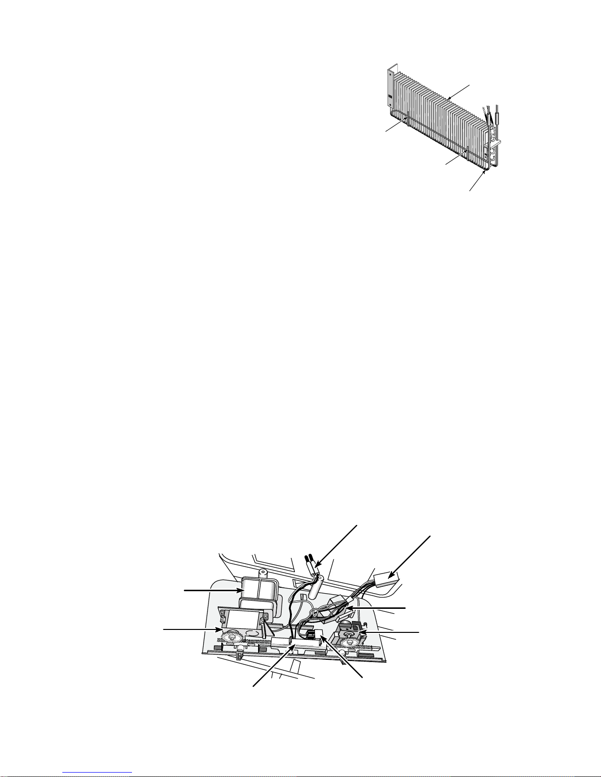
9. remove the two (2) clips securing the
heater to the evaporator bottom and slide
the heater down until it disengages from
Fig. 21
Evaporator
the evaporator. (Fig. 21)
Retaining Clip
Retaining Clip
Defrost Heater
Accessing Components in the Refrigerator Section
Accessing the Control Box
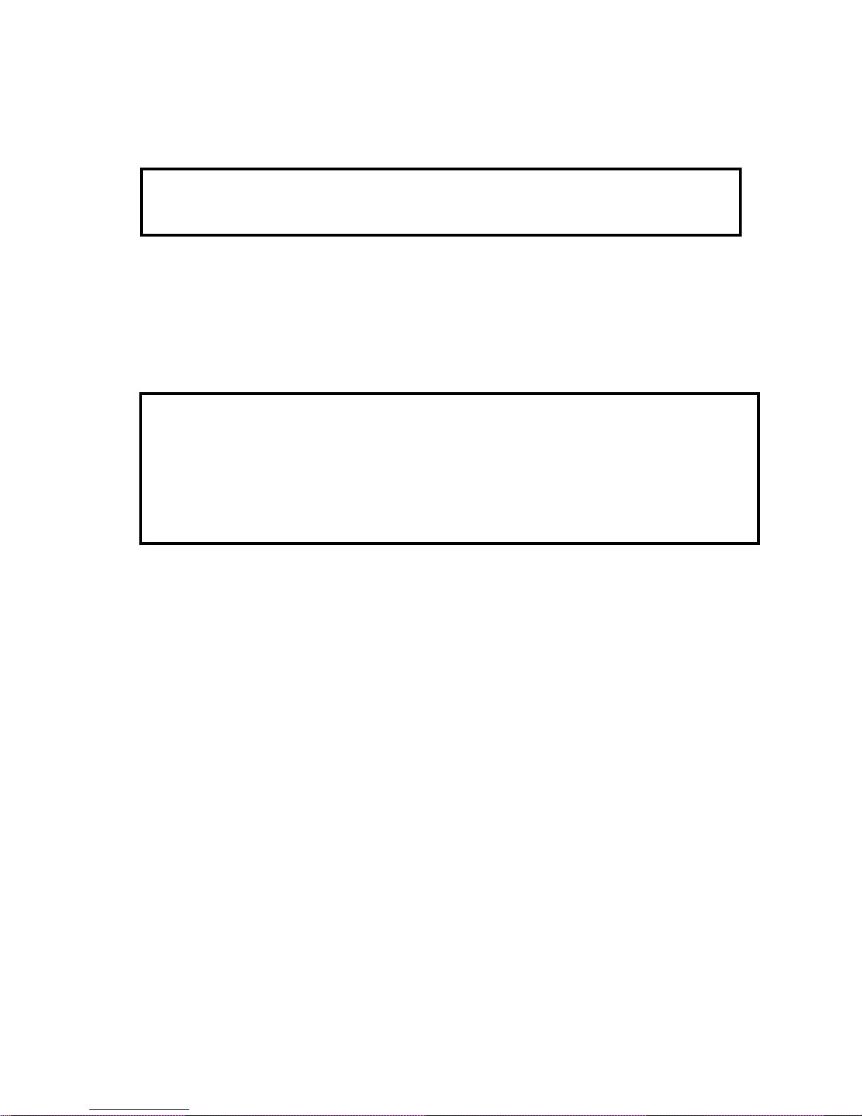
The control box is located at the front of the refrigerator section and is secured to the refrigerator
compartment ceiling. The control box contains:
• The cold air damper control
• The defrost timer
• Freezer temperature control thermostat
• The switch for the refrigerator compartment lights
• Mullion moisture control switch
1. Remove the two (2) Phillips-head screws securing the front of the control box to the ceiling to
the refrigerator section.
2. Remove the two (2) Phillips-head screws hidden inside the standoffs at the back of the control
box.
3. Move the temperature controls toward the center of the control box to prevent the control racks
from interfering with the removal of the control box.
4. Lower the control box down. Carefully pull the freezer temperature-sensing tube from the hole
in the divider between the freezer and refrigerator compartments.
5. Unplug the six-pin wiring harness connector block and the violet and blue wire connectors.
Violet & Blue Wire Connectors
Wiring
Harness
Connector
Air
Damper
Air
Damper
Control
Defrost
Timer
Thermostat
Mullion Heater
Switch
The control box can now be removed from the refrigerator compartment. (Fig. 22)
Light
Switch
Fig. 22
12
Page 20
Removing the Damper Control
1. Remove the control box from the unit.
2. Unclip the damper control from the two mounting posts and slide it up and off the posts.
NOTE: Before installing a service replacement damper, rotate the control shaft full
counterclockwise. Install the rack slide in the far right position to synchronize
the damper setting properly.
Removing the Freezer Temperature Control
1. Remove the control box from the unit. (Fig. 22 - page 12)
2. Unclip the freezer temperature control from the mounting post and lift it off.
3. Remove the gasket material and electrical wiring tape securing the temperature -sensing tube
to the control box and unclip the tubing from the stud.
NOTE: Before installing a service replacement freezer temperature control, rotate the
control shaft fully counterclockwise. Install the rack slide to the far right position
to synchronize the thermostat setting properly.
When reassembly the control box, make sure the temperature-sensing tube is
clipped in placing and taped to the control box stud. Slide the insulating cap
over the tube and onto the post to seal the hole in the divider between the
freezer and refrigerator compartments.
Removing the Defrost Timer
1. Remove the control box from the unit.(Fig. 22 - page 12)
2. Unclip the timer from the mounting post.
3. Unplug the the wiring harness connector from the timer terminals.
Removing the Light Switch
1. Remove the control box from the unit.(Fig. 22 - page 12)
2. Snap the switch out of its mounting hole in the control box.
3. Unplug the wire connectors from the switch terminals.
Removing the Exterior Cabinet Moisture Switch
1. Remove the control box from the unit.(Fig. 22 - page 12)
2. Remove the plastic insultation from the switch.
3. Unclip the switch from between the mounting posts.
4. Unplug the wires from the switch terminals.
13
Page 21

Accessing The Mullion Heater
1. Remove the doors and center hinge.
2. Remove the Phillips-head screw in the ceiling of the refrigerator compartment that secures the
center mullion cover to the cabinet.
3. Press in on one side of the mullion cover and slide it until the opposite side clears the cabinet
flange.
4. Remove the mullion cover.
5. Unplug the wire connectors from the mullion heater terminals and remove the mullion heater.
SECTION THREE
CONFIRMATION OF LEARNINGCONFIRMATION OF LEARNING
CONFIRMATION OF LEARNING
CONFIRMATION OF LEARNINGCONFIRMATION OF LEARNING
EXERCISESEXERCISES
EXERCISES
EXERCISESEXERCISES
In the blank to the left of the statement, place a T if the statement is TRUE or an F if the statement
is FALSE.
___1. The thermostat to control temperature in the freezer section is located in the refrigerator
compartment.
___ 2. The heat exchanger and main wiring harness is accessible behind a panel attached to the
back of the cabinet.
___ 3. The defrost timer is located in a box behind the toe grille at the bottom of the unit.
___ 4. The automatic damper control that regulates air flow into the refrigerator compartment
must be disconnected from the wiring harness when it is to be replaced.
___ 5. The defrost bi-metal thermostat is attached to the back wall of the freezer compartment.
If a 1998 Model “G” 25 cu. ft. Top-Mount Refrigerator/Freezer is available, perform the following
service procedures:
A. Perform all the steps necessary to pull the component compartment slide-out tray out a few
inches to access the compressor and condenser fan.
B. Perform all steps necessary to remove the defrost heater element from the evaporator.
C. Perform all steps necessary to remove the temperature control thermostat from the control
box.
D. Perform all steps necessary to remove the damper door assembly and damper control
thermostat.
14
Page 22
SECTION FOUR
TROUBLESHOOTING AND DIAGNOSTICSTROUBLESHOOTING AND DIAGNOSTICS
TROUBLESHOOTING AND DIAGNOSTICS
TROUBLESHOOTING AND DIAGNOSTICSTROUBLESHOOTING AND DIAGNOSTICS
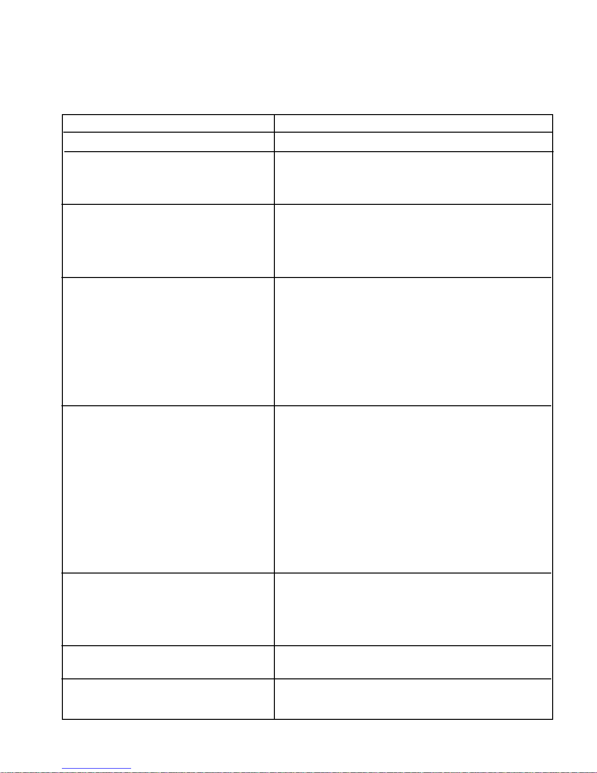
TROUBLESHOOTING GUIDE
PROBLEM
1. Operating Sound Level A. See owners manual for explanation of normal operating sound
2. Freezer Warm - Compressor Off A. Temperature Control defective or setting too warm
B. Defrost control stalled in defrost mode (defective)
C. Compressor defective
D. Overload and/or relay defective
3. Too Cold in Refrigerator A. Refrigerator damper control knob set too cold
B. Refrigerator damper control not closing
C. Freezer temperature control knob set too cold
D. Restricted condenser air
E. Refrigerant shortage or restriction
F. Overcharge
4. Freezer Warm - Compressor Cuts A Heavy usage and/or high ambient
Off on Overload B. Restricted condenser air
C. Compressor machine compartment back cover is missing
D. Cabinet elevated off floor
E Condenser fan motor inoperative
F. Condenser fan blade loose or missing
G. Improper voltage
H. Relay or overload faulty
I. Compressor motor winding open
J. Non-condensables in system
K. Overcharge
POSSIBLE CAUSE
5. Freezer Too Warm - Compressor A. Control knob set too warm
Operating B. Control out of calibration
C. Restricted condenser air
D Inoperative condenser fan motor
E. Door left open
F. Heavy usage
G. Freezer fan motor inoperative
H. Defrost thermostat open
I. Defrost heater open
J. Freezer or condenser fan blade loose or off
K. Evaporator heavily frosted
L. Defrost control stuck in compressor run mode
M. Drain plugged
N. Loss of refrigerant or restriction
O. Inefficient compressor
6. Too Warm in Refrigerator A. Refrigerator setting too warm
B. Damper doesn’t open
C Freezer control set too warm
D. Supply air duct blocked
E. Return air duct blocked
F. Heavy usage or high ambient temperature
7. Freezer Too Cold A. Freezer temperature control knob set too cold
B. Freezer temperature control out of calibration
8. Long Off Cycle - Too Warm at Start A. Low ambient temperature
B. Freezer temperature control knob set too warm
C. Freezer temperature control out of calibration
15
Page 23
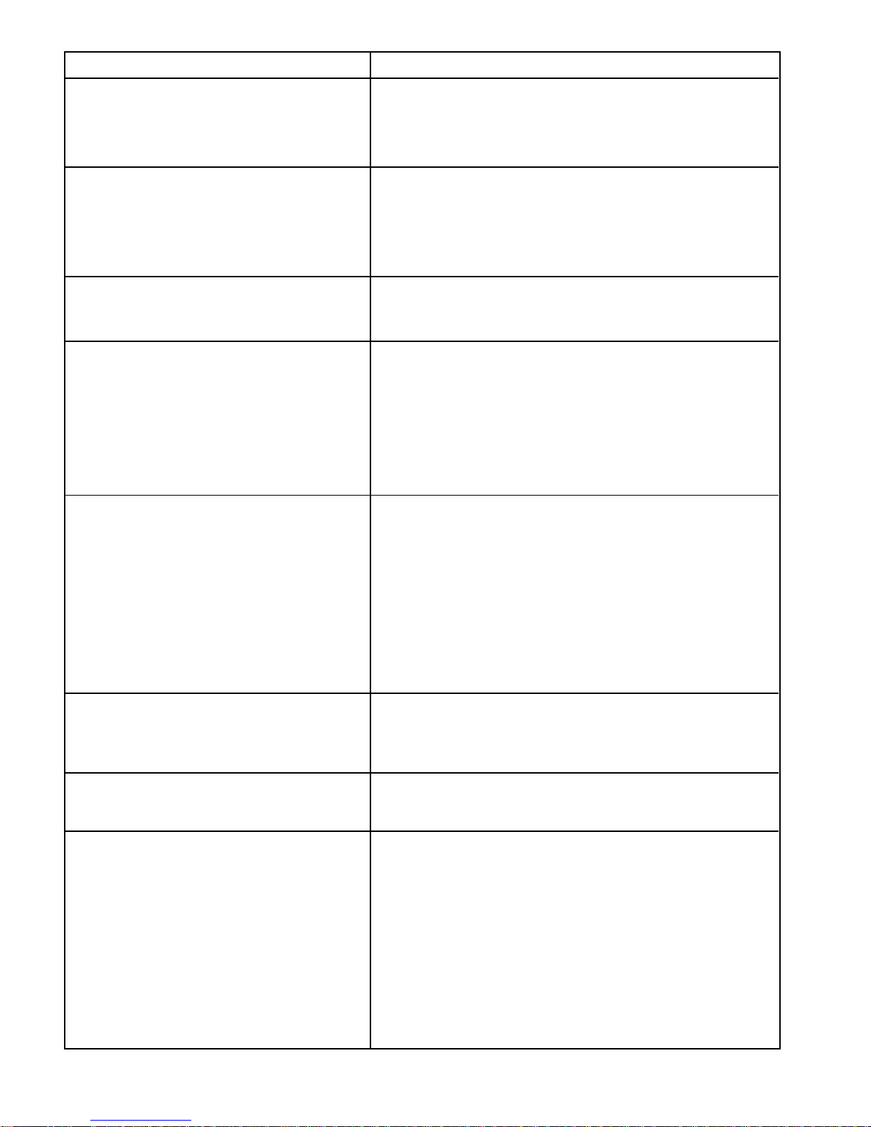
PROBLEM
9. Short off Cycle A. High ambient and/or heavy usage
B. Freezer control knob set too cold
C. Freezer control out of calibration
D. Light on constantly
E. Poor door seal
10. Long or Continuous Operation A. Heavy usage and/or high ambient
B. Inadequate condenser air flow
C. Freezer temperature set too cold
D. Freezer temperature control out of calibration
E. Freezer temperature control relay frozen closed
F. Loss of refrigerant or restriction
11. Short Run Cycle A. Low ambient and/or light usage
B. Freezer temperature control setting too warm or control out of
calibration
12. Condensation on Cabinet Exterior A. High humidity installation (design accepts bead of water on
exterior of cabinet after 4 hours with a 0° to 5°F. (-18° to -17°C.)
freezer food temperature and 38° to 40°F. (3°C to 4°C) refrigerator food temperature in 84% R.H. conditions (See example
of typical sweat pattern under above conditions on page 19.)
B. Freezer control set too cold
C. Freezer control out of calibration
D. Poor door gasket seal
E. Insulation void
POSSIBLE CAUSE
13. No Ice/Low Ice Production A. Freezer not cold enough
B. Broken locking tab on vertical cam
C. Module shut-off switch and contacts shorted and Burned
D. Motor stalled or stripped
E. Check ejector position
F. Bail shut-off arm in vacation mode - no ice
G. Bail shut-off arm binds when raised or lowered
H. Little/no alumilastic on thermometer
I. Housing to mold screws not seated
J. Heater not staked in mold
K. Wrong heater temperature
L. Broken S/O lever (miscalibrated shut-off switch)
14. Over Production of Ice A. Bail shut-off arm not in actuator
B. Misformed bail shut-off arm
C. Shut-off lever broken or bypassing vertical cam
D. Broken module actuator
15. Hollow Ice Cubes A. Water fill volume too low
B. Improper freezer airflow
C. Thermostat out of calibration
16. Flooding or Ice Slabs in Bucket or Freezer A. Thermostat out of calibration
B. Jammed cube stalled in water-fill cycle
C. Leaky water valve
D. Fill volume of water excessive
E. Motor stalled in water-fill cycle (12:00 ejector position)
F. Contaminated module
G. Refrigerator or ice maker not level
H. Excessive water pressure
I. Module shut-off switch and contacts shorted and burned
J. Broken locking tab on vertical cam (stalled in water-fill)
K. Fill-tube not properly located in fill cup
L. Fill cup water opening flashed over/plugged
M. Cubes fell over back of ice maker, melting into freezer
16
Page 24
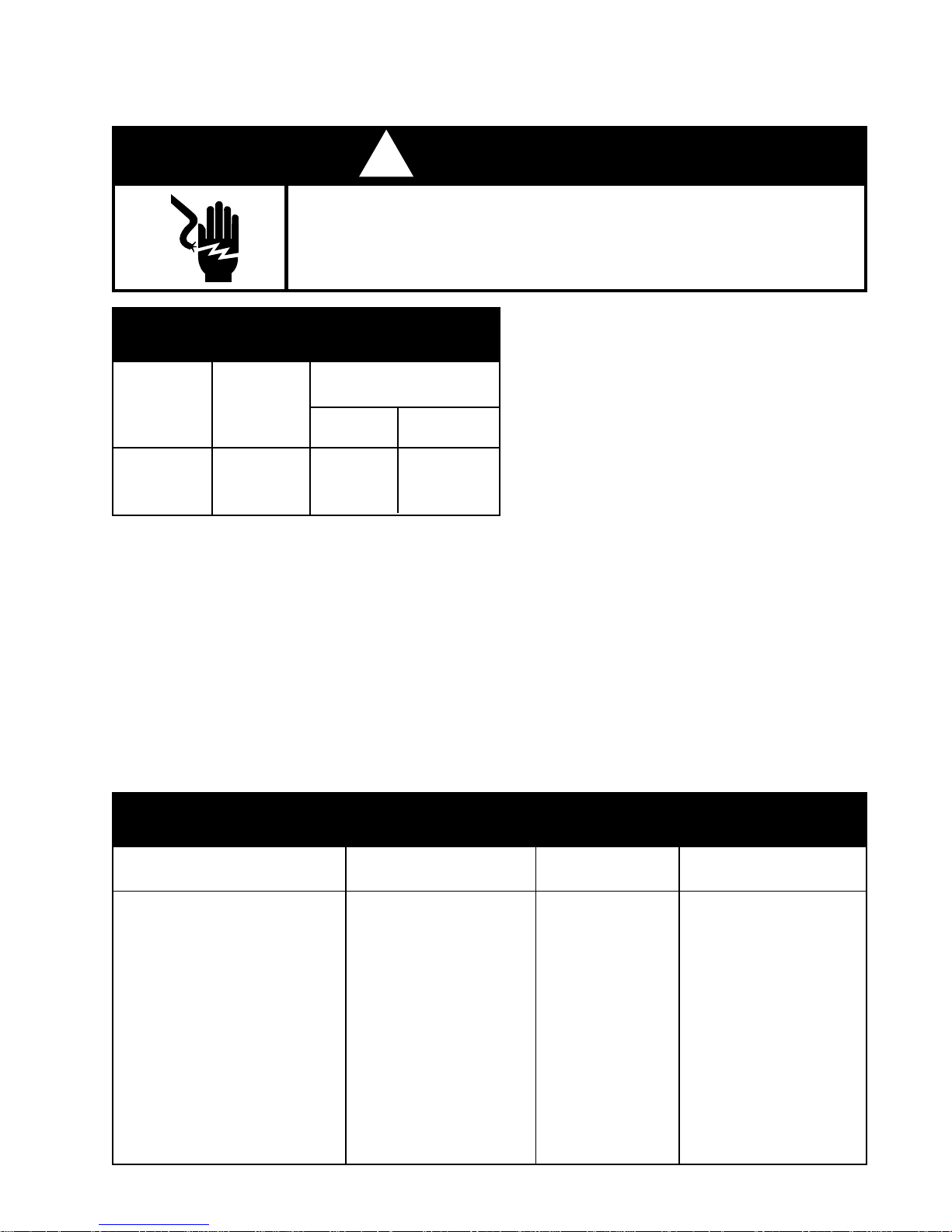
DIAGNOSTIC INFORMATION
! WARNING
ELECTRIC SHOCK HAZARD
Disconnect the electrical power before servicing any components.
Failure to do so can result in death or electrical shock.
PERFORMANCE DATE
*(NORMAL OPERATING CONDITIONS)
SYSTEM PRESSURE
(PSIG)
AMB
70°
90°
110°
WATTS
190
205
210
HIGH
SIDE
90
135
185
LOW
SIDE
1
2
2
*Normal operating conditions are viewed when
air and temperature controls are at mid-setting,
freezer section temperature is between 0°- 5°F
and unit is cycling.
NOTE: Watt and pressure readings will vary and
are influenced by existing condition of
the appliance, such as iced-up evaporator, condition of the condenser, defrost cycle, pull-down time and customer
use.
SERVICE INFORMATION
1. Do not interchange the compressor suction and process stubs.
2. Refrigerant charge must be applied to high side only.
3. Ice maker and water valve not original equipment on all models.
4. CAUTION: Ice maker cycle MUST be initiated electrically. Do not try to manually start cycle.
5. Service defrost bi-metal (55°F) open.
6. Defrost timer may contain a capacitor in series with motor. Do not continuity test when checking
for failed timer motor. Instead, energize timer and listen for gear movement.
7. Part number can be found on component.
BE SURE AND USE CORRECT REPLACEMENT PARTS
120VAC
COMPONENT
COMPRESSOR
RUN WINDING
START WINDING
PTC RELAY
OVERLOAD
RUN CAPACITOR
THERMOSTAT
DEFROST TIMER MOTOR
DEFROST HEATER
BI-METAL
EVAPORATOR FAN
CONDENSER FAN
MULLION HEATER
GENERAL COMPONENT INFORMATION
WATTAGE
@120VAC
--
--
--
--
--
--
--
.7
505
-11
10
12.1
17
OHMS
RESISTANCE
--
2.6
4.35
--
--
--
--
13000
30
--
--
--
1650
TECUMSEH
TP1380Y
12049702
--
-10097202
10377015
C8931604
RO161075
10428601
10991107
10449501
10654206
10884501
10543603
Page 25

-- NOTES --
18
Page 26
SECTION FIVE
TECH TIPSTECH TIPS
TECH TIPS
TECH TIPSTECH TIPS
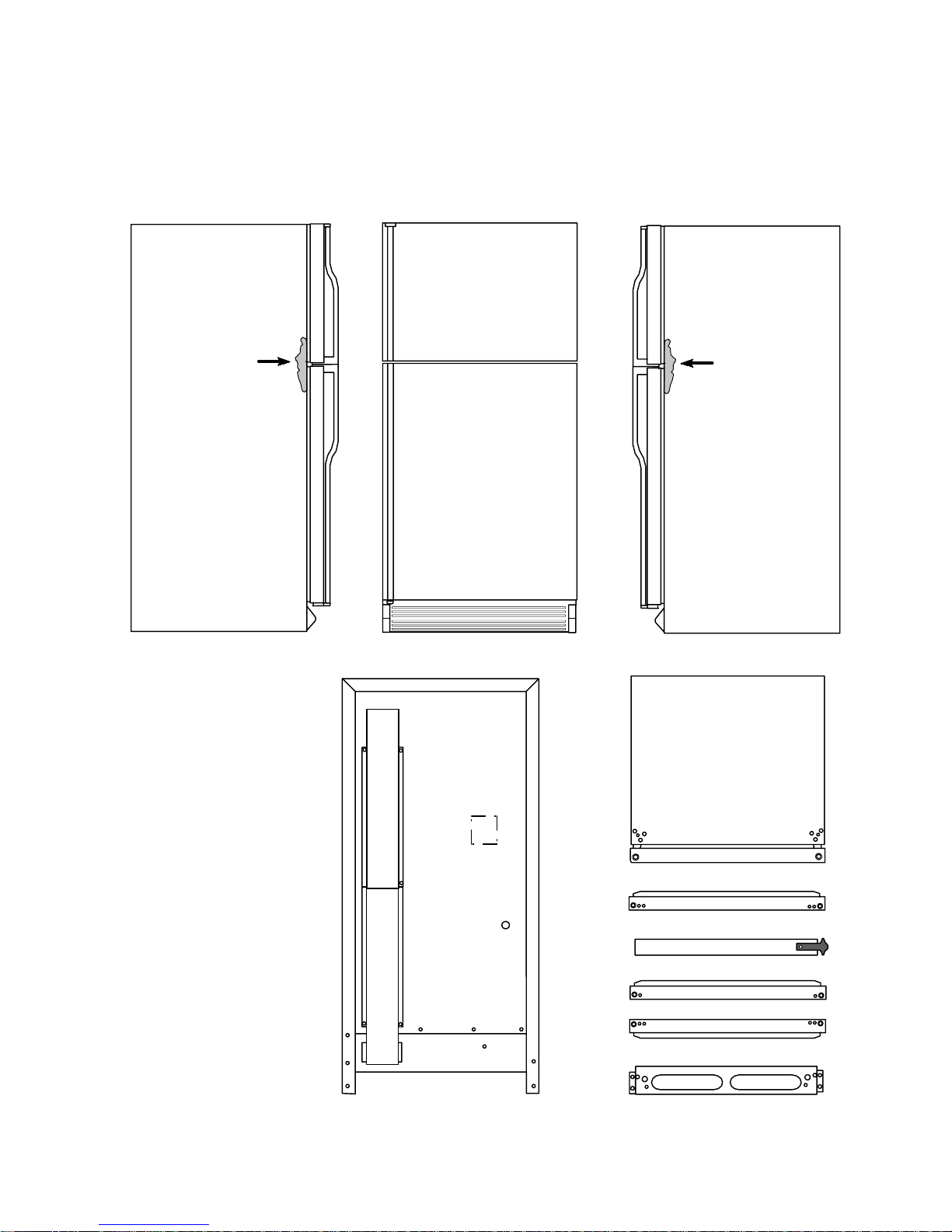
TYPICAL EXTERNAL SWEAT PATTERNS
3
LEFT SIDE
CLASSIFICATIONS OF
CONDENSATION
1 = Haze or fog
2 = Beading
3 = Beads or small drops
4 = Drops running together
3
FRONT RIGHT SIDE
BACK
BOTTOM FRZ. DOOR
CENTER MULLION
TOP REF. DOOR
BOTTOM REF. DOOR
LOWER MULLION
19
Page 27
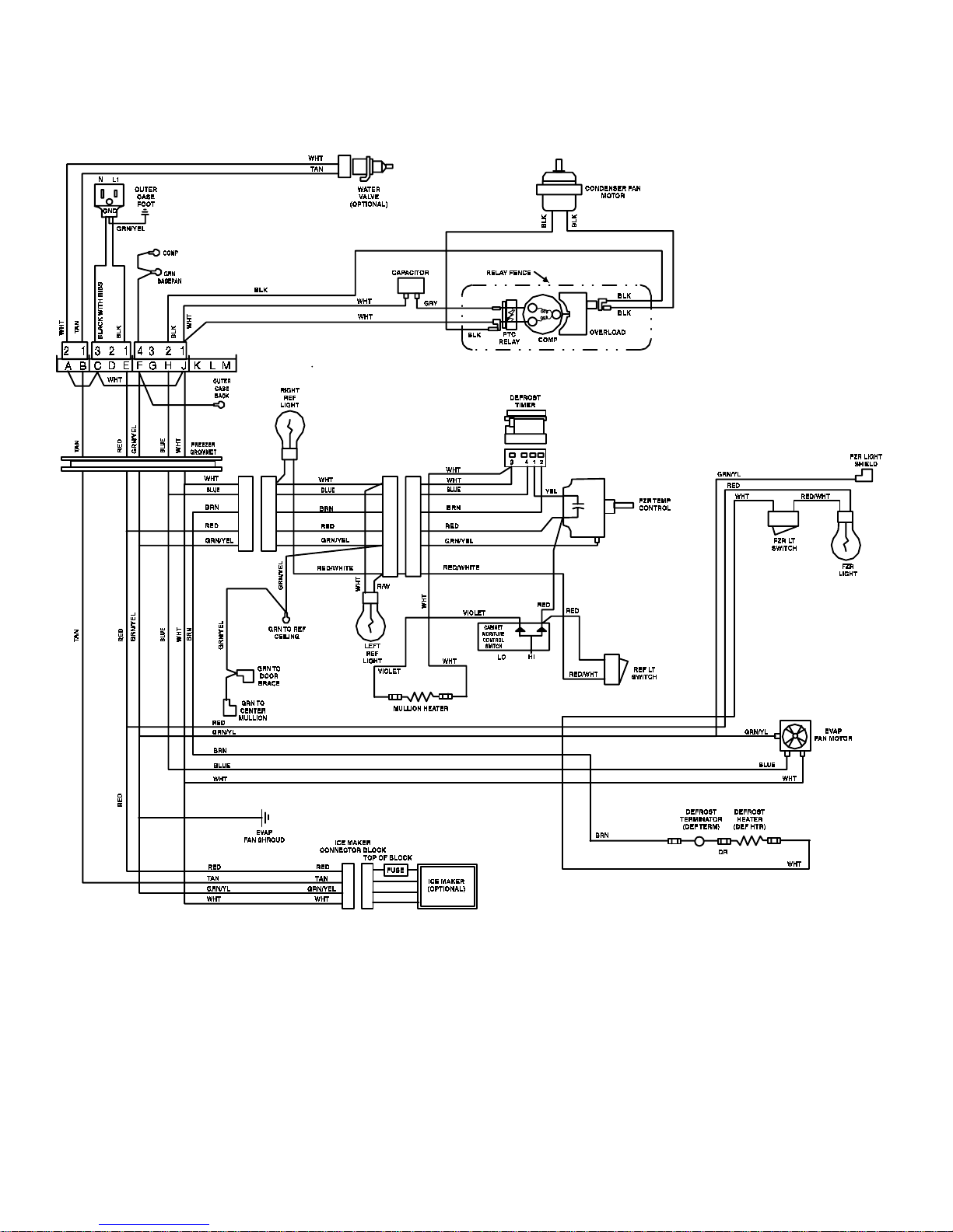
WIRING HARNESS SCHEMATIC
20
Page 28
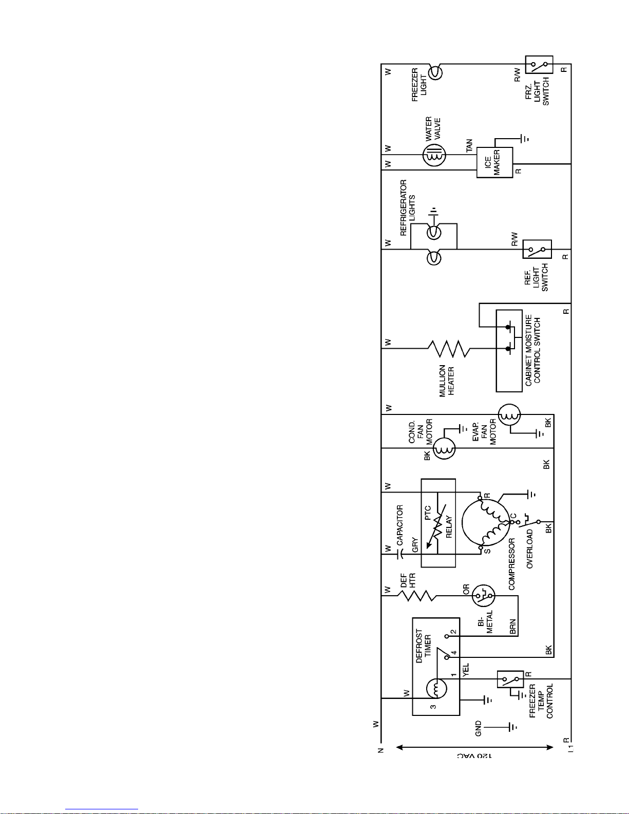
WIRING DIAGRAM
21
Page 29
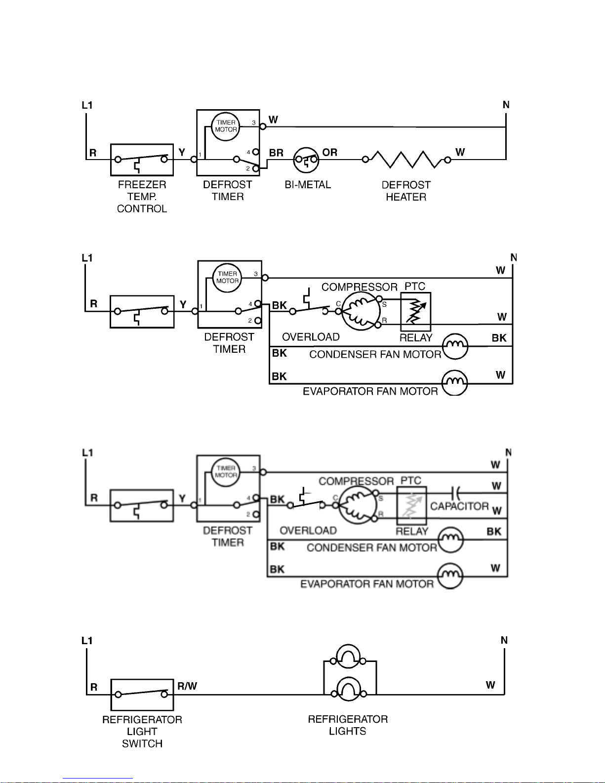
STRIP CIRCUITS
1. Defrost Circuit - Defrost Heater Energized
2. Cooling Circuit - Freezer thermostat calling for cooling (at instant of compressor start)
3. Cooling Circuit - Freezer thermostat calling for cooling (running)
4. Refrigerator Lights Circuit - Refrigerator door open
22
Page 30
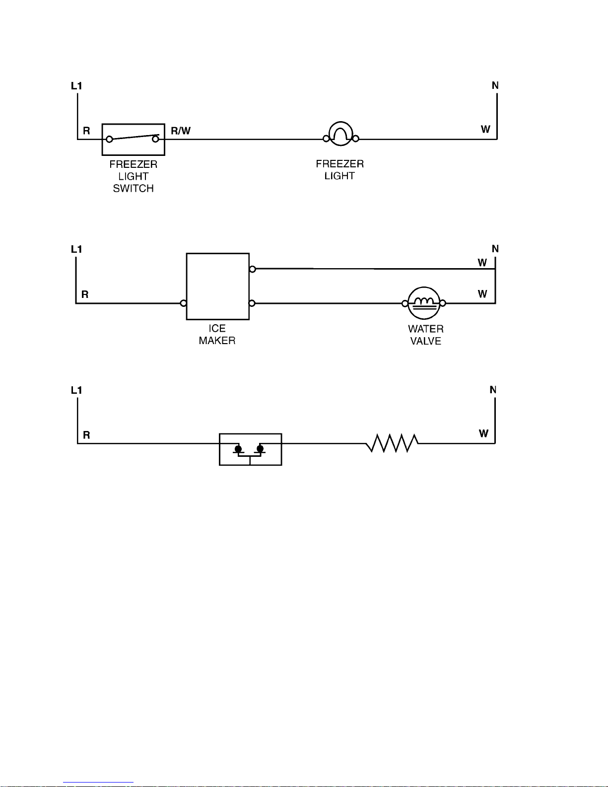
5. Freezer Light Circuit - Freezer Door Open
6. Automatic Ice Maker/Water Supply Valve Circuit
T
6. Mullion Heater Circuit
MULLION HEATER
CABINET MOISTURE
CONTROL SWITCH
23
Page 31
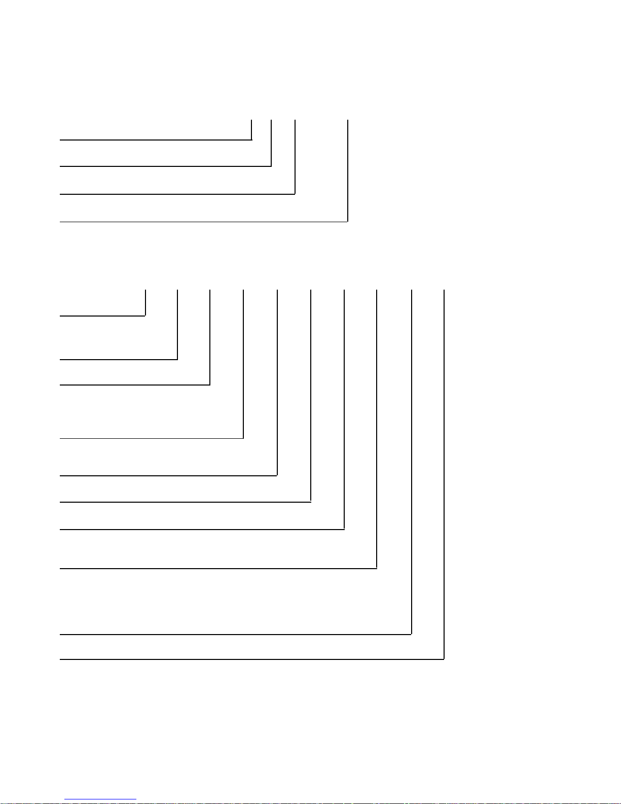
SERIAL AND MODEL NUMBER DESIGNATORS
The serial number for all Whirlpool and KitchenAid brand Refrigerator/Freezers contain the following
designations:
Manufacturer Site/Source
Calendar Year H=1998
Calendar Week
Sequential Serial Number
The model number for the KitchenAid brand 25 cu. ft. Top Mount Refrigerator/Freezers contains the
following designations:
Model Number
Marketing Channel
(if present)
KitchenAid Brand = K
Product Identification
TR = Top-Mount Freestanding
Reversible Door Swing
KTRS 25 K G WH 00
EC H 39 40174
Merchandise Scheme/Series
S = Superba
Capacity
Features - Accepts Ice Maker Kit
Year of Introduction
G= 1998
Color
WH = White
AL = Almond
BL = Black
Engineering Changes (Numeric)
24
Page 32
WW
ARRANTYARRANTY
ARRANTY
W
ARRANTYARRANTY
WW
KitchenAid Refrigerators
LENGTH OF
WARRANTY:
ONE YEAR FULL
WARRANTY
FROM DATE OF
PURCHASE
SECOND THROUGH
FIFTH YEAR FULL
WARRANTY
FROM DATE OF
PURCHASE
SIXTH THROUGH
TENTH YEAR
LIMITED
WARRANTY
FROM DATE OF
PURCHASE
LIMITED LIFETIME
WARRANTY
SECOND YEAR
THROUGH LIFE OF
PRODUCT FROM
DATE OF PURCHASE
KITCHENAID
WILL PAY FOR:
Replacement parts and repair labor costs
to correct defects in materials or
workmanship. Service must be provided
by an authorized KitchenAid servicing
outlet.
Replacement or repair of the
refrigerator/freezer cavity liner, (including
labor costs.) If the part cracks due to
defects in materials or workmanship.
Service must be provided by an
authorized KitchenAid servicing outlet.
Replacement parts and repair labor costs
to correct defects in the sealed
refrigeration system.
These parts are:
1. Compressor; 2. Evaporator
3. Condenser; 4. Drier
5. Connecting Tubing
Servicing must be provided by an
authorized KitchenAid servicing outlet.
Replacement parts and repair labor costs
to correct defects in the sealed
refrigeration system.
These parts are:
1. Compressor; 2. Evaporator
3. Condenser; 4. Drier
5. Connecting Tubing
Replacement of all SLIDE 'N' LOCK Door
Bins and SLIDE 'N' LOCK Can Racks due
to defective materials or workmanship.
KITCHENAID
WILL NOT PAY FOR:
A. Service calls to:
1. Correct the installation of the refrigerator.
2. Instruct you how to use the refrigerator.
3. Replace house fuses or correct house
wiring.
4. Replace house plumbing.
B. Repairs when refrigerator is used in other
than normal home use.
C. Damage resulting from accident, alteration,
misuse, abuse, fire, flood, acts of God,
improper installation, or installation not in
accordance with local electrical codes or
plumbing codes.
D. Any food lose due to product failure.
E. Any labor costs during the limited warranty.
F. Replacement parts or repair labor costs for
units operated outside the United States or
Canada.
G. Pickup and delivery. This product is
designed to be repaired in the home.
H. Repairs to parts or systems caused by
unauthorized modifications made to the
appliance.
I. In Canada, travel or transportation expenses
for customers who reside in remote areas.
KITCHENAID AND KITCHENAID CANADA DO NOT ASSUME ANY RESPONSIBILITY FOR INCIDENTAL OR
CONSEQUENTIAL DAMAGES. Some states or provinces do not allow the exclusion or limitation of incidental or
consequential damages, so this exclusion or limitation may not apply to you.
This warranty gives you specific legal rights, and you may also have other rights which may vary from state to
state or province to province.
Outside the United State and Canada, a different warranty may apply. For details please contact your
authorized KitchenAid dealer.
If you need service, first see the "Troubleshooting Guide" section of this book. After checking the "Troubleshooting
Guide," additional help can be found by checking the "Requesting Assistance or Service" section or by calling our
Consumer Assistance Center, 1-800-442-1230 (toll free), from anywhere in the U.S.A. For service in Canada, see the
"Requesting Assistance or Service" section.
25
Page 33

-- NOTES --
26
Page 34

For the way it's made.™
X
 Loading...