

KitchenAid electric dryer Installation Instructions Manual
Installation Instructions
Electric
Dryer
Befotv you
start...
A
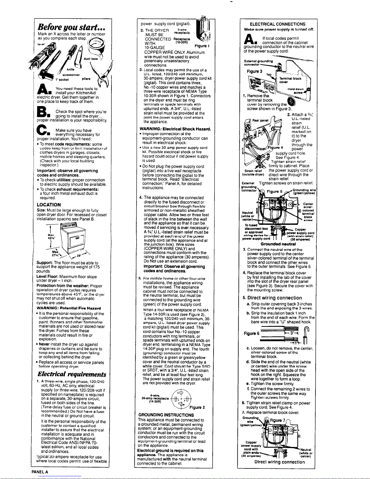
You need these tools to
n install your KItchenAid
electric dryer. Get them together in
one place to keep track of them.
B
n
Check the spot where you’re
going lo install the dryer...
proper mstallation is your responsibility.
C
w
Make sure you have
everything necessary for
proper inslallatron. You’ll need:
l
To meet code requirements: some
codes keep from or limit installation of
clothes dryers rn garages, closets,
mobile homes and sleeping quarters.
(Check with your local building
inspector.)
Important: observe all governing
codes and ordinances.
l
To check utilities: proper connectron
to electric supply should be available.
l
To check exhaust requirements:
a four inch metal exhaust duct is
required.
LOCATION
Size: Must be large enough to fully
open dryer door. For recessed or closet
installatron spacinq see Panel 8.
Support: The floor bust be able to
support the applrance weight of 175
pounds
Level Floor: Maximum floor slope
under dryer - 1 inch.
Protection from the weather: Proper
operation of drver cvcles reouires
temperatures above 45”F., o;~the dryer
may not shut off when automatic
cycles are used.
WARNING: Potential Fire Hazard
m It is the personal responsibility of the
customer to ensure fhat oasoline.
paint, thinners and other flammable
malerrals are not used or stored near
the dryer. Fumes from these
materials could result in fire or
explosion.
b Never install the dryer up against
draperies or curtains and be sure to
keep any and all items from fallmg
or collectmg behind the dryer
D Replace all access or service panels
belore operating dryer.
Electrical tvquhments
1. A three-wire, srngle phase, 120/240volt, 60.Hz. AC only, electrical
supply (or three-wire, 120/206volt if
specified on nameplate) is required
on a separate, 30-ampere circuit,
fused on both sides of the line.
(Time-delay fuse or circuit breaker is
recommended.) Do Not have a fuse
rn the neutral or ground circuit.
It is the personal responsibility of the
customer to contact a quaIlfred
k-staller to assure that the electrical
lnstallatlon is adequate and in
conformance with the National
Electrical Code ANSVNFPA 70latest edition, and all local codes
and ordinances,
Typical 30-ampere receptacle for use
rvhere local codes permit use of flexible
power supply cord (pigtail).
2. THE DRYER ,Ls+$,.
MUST BE
CONNECTED
Recep1(1cIn
WITH
(104OR)
IO-GAUGE
COPPER WIRE ONLY Aluminum
wire must not be used to avord
potentially unsatisfactory
connections.
I ..-.
3 Local codes may permit the use of a
U L Iksted. 120/240-volt minimum.
30.ampere. dryer power supply cord kit
(piglail). This cord contains three,
No:10 copper wires and malches a
three-wire receptacle of NEMA Type
10.30R shown in Figure 1. Conneclors
1 onl~edryerendmustbertng 1
lermmals or soade termrnals with
upturned ends. A 3/4”, U.L.-listed
slrain reliel musl be provided at Ihe
poinl the power supply cord enlers
the appliance.
WARNING: Electrical Shock Hazard.
l
Improper connection d the
equipment-grounding conductor can
result in electrical shock.
l
Use a new 30.amp power supply cord
kil. Possible electrical shock or fire
hazard could occur il old power supply
is used.
l
Do Not plug the power supply cord
(pigtall) rnlo a live wall receptacle
before connecting the pigtail to the
termrnal block. Read “Electrical
connection:’ Panel A, for detailed
instructions.
4. The appliance may be connected
direclly to the fused disconnect or
circuit breaker box throuqh flexible
armored or non-metallicsheathed
coooer cable. Allow two or three feet
of siack in the line between the wall
and the appliance so that it can be
moved if servicing is ever necessary.
A%:’ U.L.-listed strain relief must be
provided at each end of the power
supply cord (at the appliance and at
the junction box). Wire sizes
(COPPER WIRE ONLY) and
connections must conform with the
rating of the appliance (30 amperes).
Do Not use an extension cord.
Important: Observe all governing
codes and ordinances.
5. For mobile home or other four-wire
inslallations, the appliance wiring
must be revised. The appliance
cabinet must not be connected to
the neutral terminal, but must be
connected to the grounding wire
(green) of the power supply cord.
When a four-wire receptacle of NEMA
TVD~ 14.30R is used fsee Fioure 21.
a ‘malching 120/240-volt mir&um:30-
ampere, U.L. listed dryer power supply
cord kil (piglarl) must be used. This
cord contains four No.-1 0 copper
conductors with nng terminals, or
spade terminals with uplurned ends on
drver end. terminatkta in a NEMA Tv~e
14.30P plug on supply end. The lou’rih
(grounding) conductor must be
identified by a green or green/yellow
cover and the neutral conduclor by a
white cover. Cord should be Type SRD
or SRDT, wilh a 3/4’. U.L.-listed slrain
relief. and be at least (our feet long.
The power supply cord and strain relief
are nol provided wilh the dryer.
GROUNDING INSTRUCTIONS
This appliance must be connected to
a grounded metal, permanent wirinq
or an equipment-grounding
conductor must be run with the circuit
conductors and connected to Ihe
equipment-grounding terminal or lead
on the aooliance.
I
Electrlc~l’ground is required on this
aoollanm. This aooliance is
manufactured wlih’the neutral terminal
connected lo the cabinet.
ELECTRICAL CONNECTIONS
Make sure power supply is turned off.
A
If local codes permit
n connection of the cabinet
grounding conductor to the neutral wire
of the power supply cord:
screw shown in Fygure 3:
2. Attach a %:
the power supply cord or
(outsrde drlsrt direcl wire through the
strain relief
External Tiahten screws on strain relief.
Groundedneutml
3. Connect the neutral wire of the
power supply cord to the center
silver-colored lerminal of the terminal
block and connect the other wires
to the outer terminals. See Figure 5.
4. Replace the terminal block cover
by first installing the tab of the cover
into the slot of the dryer rear panel
(see Figure 3). Secure the cover wilh
the mounting screw.
5. Direct wiring connection
a. Strip outer covering back 3 inches
from the end exposing the 3 wires.
b. Strip the insulatron back 1 inch
from the end of each wire. Form the
bare wire into a “U” shaped hook.
FigureSw
----_a
-ll”t
C. Loosen, do
not
remove, the center,
silver-colored screw of the
terminal block.
d. Slide the end of the neutral (white
or center) wire under the screw
head with the open side of the
hook on the right. Squeeze the
wire together to form a loop.
e. Tiahten the screw firmlv.
1. C&nect the remaining’2 wires to
the outer screws the same wav.
’ Tighten screws firmly.
6. Tighten strain relief clamp on power
supply cord. See Figure 4.
7. Replace terminal block cover.
I
Direct wlrlng connectlon
PANEL A
 Loading...