


30" (76.2 CM) AND 36" (91.4 CM) ELECTRIC
DOWNDRAFT COOKTOP
INSTALLATION INSTRUCTIONS
INSTRUCTIONS D'INSTALLATION DE LA TABLE DE CUISSON ÉLECTRIQUE AVEC ASPIRATION PAR LE BAS DE 30" (76,2 CM) ET 36" (91,4 CM)
Table of Contents/Table des matières
COOKTOP SAFETY........................................................................ |
2 |
INSTALLATION REQUIREMENTS ................................................ |
3 |
Tools and Parts ............................................................................ |
3 |
Location Requirements ................................................................ |
3 |
Venting Requirements.................................................................. |
5 |
Venting Methods .......................................................................... |
6 |
Electrical Requirements .............................................................. |
8 |
INSTALLATION INSTRUCTIONS .................................................. |
9 |
Prepare Cooktop .......................................................................... |
9 |
Install Foam Strip.......................................................................... |
9 |
Rotate Blower - Optional.............................................................. |
9 |
Install Cooktop ........................................................................... |
11 |
Make Electrical Connection ....................................................... |
11 |
Complete Installation.................................................................. |
12 |
SÉCURITÉ DE LA TABLE DE CUISSON ................................. |
13 |
EXIGENCES D'INSTALLATION................................................ |
14 |
Outils et pièces........................................................................ |
14 |
Exigences d’emplacement...................................................... |
14 |
Exigences concernant l'évacuation ........................................ |
16 |
Méthodes d'évacuation........................................................... |
17 |
Spécifications électriques ....................................................... |
19 |
INSTRUCTIONS D’INSTALLATION ......................................... |
20 |
Préparation de la table de cuisson ......................................... |
20 |
Installation de la bande de mousse ........................................ |
20 |
Rotation du ventilateur - Facultative....................................... |
20 |
Installation de la table de cuisson........................................... |
22 |
Raccordement électrique........................................................ |
22 |
Achever l'installation ............................................................... |
23 |
IMPORTANT:
Save for local electrical inspector's use.
IMPORTANT :
À conserver pour consultation par l'inspecteur local des installations électriques.
W10298568A
COOKTOP SAFETY
Your safety and the safety of others are very important.
We have provided many important safety messages in this manual and on your appliance. Always read and obey all safety messages.
This is the safety alert symbol.
This symbol alerts you to potential hazards that can kill or hurt you and others.
All safety messages will follow the safety alert symbol and either the word “DANGER” or “WARNING.” These words mean:
 DANGER
 WARNING
You can be killed or seriously injured if you don't immediately follow instructions.
You can be killed or seriously injured if you don't follow instructions.
All safety messages will tell you what the potential hazard is, tell you how to reduce the chance of injury, and tell you what can happen if the instructions are not followed.
2
INSTALLATION REQUIREMENTS
Tools and Parts
Gather the required tools and parts before starting installation. Read and follow the instructions provided with any tools listed here.
Tools needed
■ |
Tape measure |
■ |
Marker or pencil |
■ |
Flat-blade screwdriver |
■ |
Pliers |
■ |
Phillips head screwdriver |
■ |
¼" drill bit |
■ |
Drill |
■ |
Jigsaw |
■ |
Level |
■ |
Ratchet with ³⁄"socket |
■6" socket extension
Parts supplied
■Vent grille
■Pre-filter
Parts needed
■A UL listed or CSA approved strain relief for ⁄" (2.2 cm) knockout.
■A UL listed or CSA approved conduit connector for ¹⁄" (1.3 cm) trade-size metal-clad conduit
■UL listed wire connectors
■Metal ducting
■Wall cap
6" (15.2 cm) Round Surface Wall Cap Damper Order Part Number A406
5" (12.7 cm) Round Surface Wall Cap Damper Order Part Number A405
3¼" x 10" (8.3 x 25.4 cm) Surface Wall Cap Damper Order Part Number A403
To order, see the “Assistance or Service” section of the Use and Care Guide.
■Vent clamps
Check local codes. Check existing electrical supply. See “Electrical Requirements” section.
It is recommended that all electrical connections be made by a licensed, qualified electrical installer.
Location Requirements
IMPORTANT: Observe all governing codes and ordinances. When installing cooktop, use minimum dimensions given.
■To eliminate the risk of burns or fire by reaching over the heated surface units, cabinet storage space located above the surface units should be avoided. If cabinet storage is to be provided, the risk can be reduced by installing a range hood that projects horizontally a minimum of 5" (12.7 cm) beyond the bottom of the cabinets.
■Use the countertop opening dimensions that are given with these Installation Instructions. Given dimensions are minimum clearances and provide 0" (0 cm) clearance.
■Grounded electrical supply is required. See “Electrical Requirements” section.
■If cabinet has drawers, drawers will need to be removed and drawer fronts installed on front of cabinet.
IMPORTANT: An under-counter built-in oven cannot be installed under this product.
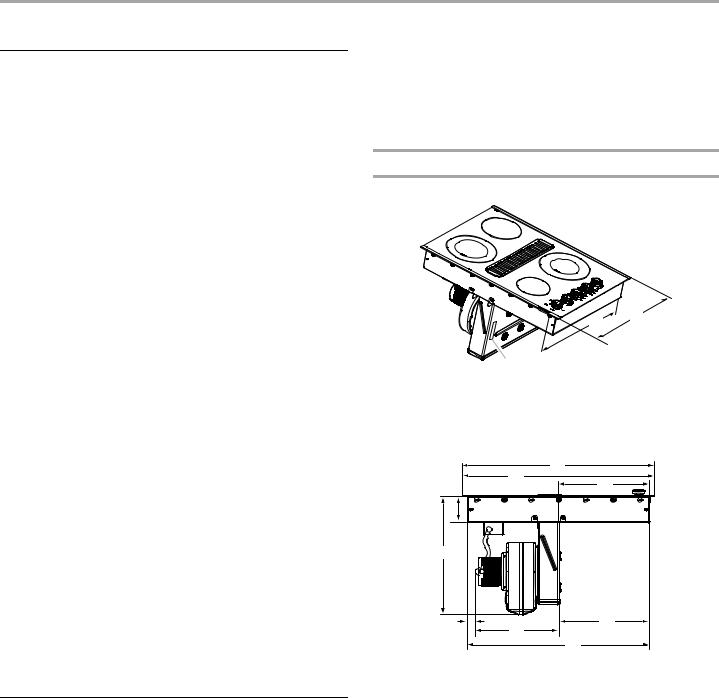
Product Dimensions
30" (76.2 cm) Cooktop - for standard and electric models
C
B
A
A.Model/serial rating/clearance plate location
B.21" (53.4 cm) screw head to screw head
C.22" (52.3 cm) without stainless steel trim or 21³ ⁄" (54.8 cm) with stainless steel trim
A
B
C
D
E
F |
H |
G
I
A.30¹⁄" (76.3 cm) with stainless steel trim
B.29¹ ⁄" (76.1 cm) without stainless steel trim
C.14⁄" (36.4 cm)
D.3³¹⁄" (10.1 cm)
E.18¹³⁄" (46.8 cm)
F. 1¹¹⁄" (3.4 cm)
G.13³⁄" (33.3 cm)
H.14³⁄" (36.0 cm)
I.28⁄" (72.7 cm) screw head to screw head
3

36" (91.4 cm) Cooktop - for standard and electric models
C
B
A
A.Model/serial rating/clearance plate location
B.21" (53.4 cm) screw head to screw head
C.22" (52.3 cm) without stainless steel trim or 21³ ⁄" (54.8 cm) with stainless steel trim
|
|
A |
|
B |
|
|
|
C |
D |
|
|
E |
|
|
F |
G |
H |
|
|
I |
A.35² ⁄" (90.1 cm) with stainless steel trim
B.35² ⁄" (89.9 cm) without stainless steel trim
C.17³¹⁄" (43.8 cm)
D.3² ⁄" (9.6 cm)
E.18¹³⁄" (46.8 cm)
F. 8¹ ⁄" (20.9 cm)
G.13³⁄" (33.3 cm)
H.13¹⁄" (33.2 cm)
I.34³¹⁄" (87.6 cm) screw head to screw head
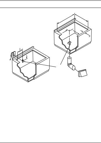
Cabinet Dimensions
A
 D
D
C |
B |
|
L F G
E
 H
H
I
K J
A.30" (76.2 cm) on 30" (76.2 cm) models 36" (91.4 cm) on 36" (91.4 cm) models
B.Combustible area above countertop (shown by dashed box above)
C.30" (76.2 cm) minimum clearance between top of cooktop platform and bottom of uncovered wood or metal cabinet (24" [61 cm] minimum clearance if bottom of wood or metal cabinet is covered by not less than ¹⁄" [0.6 cm] flame retardant millboard covered with not less than No. 28 MSG sheet steel, 0.015" [0.04 cm] stainless steel, or 0.024" [0.06 cm] aluminum or 0.020" [0.05 cm] copper)
D.13" (33 cm) recommended upper cabinet depth
E.2" (5.1 cm)
F. 21¹⁄" (73.4 cm)
G.18" (45.7 cm) minimum clearance from upper cabinet to countertop within minimum horizontal clearances to cooktop
H.Junction box or outlet; 12" (30.5 cm) minimum from bottom of countertop
I.Junction box or outlet; 10" (25.4 cm) from right-hand side of cabinet
J.28⁄" (73.4 cm) on 30" (76.2 cm) models 34⁄" (87.8 cm) on 36" (91.4 cm) models
K.2½" (6.4 cm) minimum distance to nearest left and right side combustible surface above cooktop
L.1½" (3.8 cm) minimum clearance between back wall and countertop
NOTES: After making the countertop cutout, some installations may require notching down the base cabinet side walls to clear the cooktop base. To avoid this modification, use a base cabinet with sidewalls wider than the cutout.
■A minimum side clearance of 6" (15.2 cm) is recommended between side of cooktop and side wall for maximum ventilation performance.
■A minimum clearance of 2" (5.1 cm) is recommended between the motor/blower and cabinet for proper cooling. A 6" (15.2 cm) clearance is recommended for servicing access.
4
Cutout Dimensions
A B
 D
D
 C
C
E
F
H
 I
I
J
G
A.28⁄" (73.4 cm) maximum on 30" (76.2 cm) models 34⁄" (87.8 cm) maximum on 36" (91.4 cm) models
B.21¹⁄" (53.7 cm) maximum on both 30" (76.2 cm) and 36" (91.4 cm) models
C.8¹ ⁄" (21.8 cm) on 30" (76.2 cm) models 15⁄" (39.2 cm) on 36" (91.4 cm) models
D.6¹ ⁄" (16.0 cm) on both 30" (76.2 cm) and 36" (91.4 cm) models
E.2" (5.1 cm) minimum space to front edge of cooktop
F. Floor exhaust option
G.6¹⁄" (15.6 cm) for 6" (15.2 cm) vent system 5¹⁄" (13 cm) for 5" (12.7 cm) vent system
H.8¹ ⁄" (21.8 cm) on 30" (76.2 cm) models 15⁄" (39.2 cm) on 36" (91.4 cm) models
I.16" (40.6 cm) on both 30" (76.2 cm) and 36" (91.4 cm) models
J.Wall exhaust option
Venting Requirements
IMPORTANT: This cooktop must be exhausted outdoors.
■Do not terminate the vent system in an attic or other enclosed area.
■Use a vent cap.
■Vent system must terminate to the outside.
■Use only a 6" (15.2 cm) diameter round or 3¼" x 10" (8.3 x 25.4 cm) rectangular vent except as follows: For
electric cooktops, a 5" (12.7 cm) diameter round vent may be used for venting straight out the back of the cooktop and directly through the wall for 10 ft (3.0 m) or less.
■Before making cutouts, make sure there is proper clearance within the wall or floor for the exhaust vent.
■Do not cut a joist or stud unless absolutely necessary. If a joist or stud must be cut, then a supporting frame must be constructed.
■The size of the vent should be uniform.
■The vent system must have a damper. If roof or wall cap has a damper, do not use damper supplied with the range hood.
■Use vent clamps to seal all joints in the vent system.
■Use caulking to seal exterior wall or roof opening around the cap.
■Determine which venting method is best for your application.
For Best Performance:
■Use 26-gauge minimum galvanized or 25-gauge minimum aluminum metal vent. Poor quality pipe fittings can reduce airflow. Flexible metal vent is not recommended.
NOTE: Local codes may require a heavier gauge material.
■Metal duct may be reduced to 30-gauge galvanized steel or 26-gauge aluminized steel if allowed by local codes. This reduction is based on information in the International Residential Codes Section M1601.1 (2006 edition).
■Do not install 2 elbows together.
■Use no more than three 90° elbows.
■If an elbow is used, install it as far away as possible from the hood’s vent motor exhaust opening.
■Make sure there is a minimum of 18" (45.7 cm) of straight vent between the elbows if more than one elbow is used.
■Elbows too close together can cause excess turbulence that reduces airflow.
■Do not use a 5" (12.7 cm) elbow in a 6" (15.2 cm) or 3¹⁄ " x 10" (8.3 x 25.4 cm) system.
■Do not reduce to a 5" (12.7 cm) system after using 6" (15.2 cm) or 3¹⁄ " x 10" (8.3 x 25.4 cm) fittings.
■Avoid forming handmade crimps. Handmade crimps may restrict airflow.
■Use a vent cap for proper performance. If an alternate wall or roof cap is used, be certain the cap size is not reduced and that it has a back draft damper.
■Use vent clamps to seal all joints in the vent system.
■Use caulking to seal exterior wall or roof opening around the cap.
The length of vent system and number of elbows should be kept to a minimum to provide efficient performance.
The maximum equivalent length of the vent system is 60 ft (18.3 m). For altitudes above 4,500 ft (1272 m), reduce recommended vent run by 20% for best performance.
Cold Weather Installations
An additional back draft damper should be installed to minimize backward cold air flow and a thermal break installed to minimize conduction of outside temperatures as part of the vent system.
The damper should be on the cold air side of the thermal break.
Makeup Air
Local building codes may require the use of makeup air systems when using ventilation systems greater than specified CFM of air movement. The specified CFM varies from locale to locale.
Consult your HVAC professional for specific requirements in your area.
5
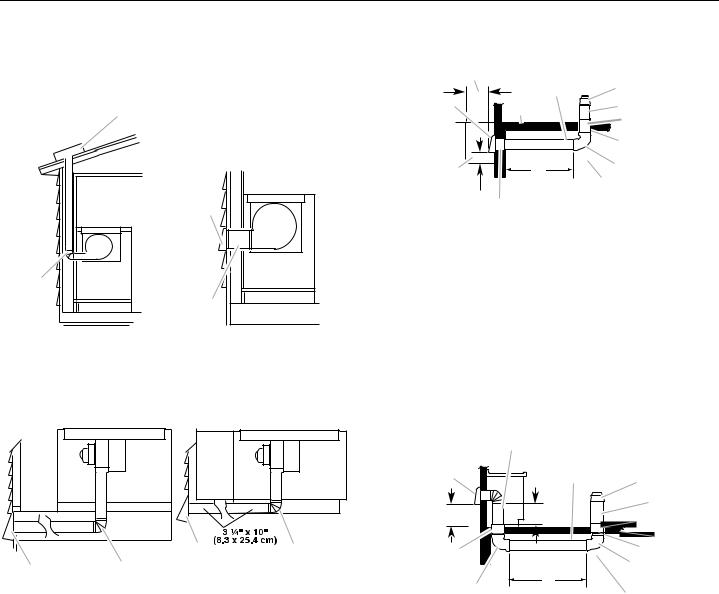
Venting Methods
Common venting methods are shown for a counter-mounted downdraft cooktop. The cooktop may be vented through the wall or floor.
Option 1 - Roof Venting
B
A
A.Roof cap
B.6" (15.2 cm) round roof venting
Option 2 - Wall Venting
B
A
A.6" (15.2 cm) round wall venting
B.Wall cap
Option 3 - Venting Between |
Option 4 - Venting behind |
Floor Joist |
Cabinet Kick Plate |
A |
B |
A.Wall cap
B.6" (15.2 cm) round wall venting
A B
A.Wall cap
B.6" (15.2 cm) round wall venting
Concrete Slab Installations -
Exhaust Through Window Well
|
B |
|
|
|
D |
E |
|
A |
C |
F |
|
|
|
G |
|
|
|
H |
|
N |
K |
I |
|
J |
|||
|
|
ML
A.Wall cap
B.12" (30.5 cm) minimum
C.Concrete slab
D.6" (15.2 cm) round PVC sewer pipe
E.5" to 6" (12.7 cm to 15.2 cm) transition F. 6" (15.2 cm) round metal duct
G.6" (15.2 cm) round PVC coupling
H.6" (15.2 cm) round PVC sewer pipe
I.6" (15.2 cm) round 90° PVC sewer pipe elbow
J.Tightly pack gravel or sand completely around pipe.
K.42 ft (12.8 m) max.
L.6" (15.2 cm) round PVC coupling
M.6" (15.2 cm) minimum
N.Window well
Concrete Slab Installations - Exhaust Through Wall
|
B |
|
A |
D |
E |
|
O |
C |
F |
|
G |
|||
|
|
||
|
|
H |
N |
I |
|
J
L
M
K
A.Wall cap
B.6" (15.2 cm) round metal vent
C.16" (40.6 cm) maximum
D.6" (15.2 cm) round PVC sewer pipe
E.5" to 6" (12.7 cm to 15.2 cm) transition F. 6" (15.2 cm) round metal duct
G.6" (15.2 cm) round PVC coupling
H.Concrete slab
I.6" (15.2 cm) round PVC sewer pipe
J.6" (15.2 cm) round 90° PVC sewer pipe elbow
K.Tightly pack gravel or sand completely around pipe.
L.30 ft (9.1 m) max.
M.6" (15.2 cm) round 90° PVC sewer pipe elbow
N.6" (15.2 cm) round PVC coupling
O.12" (30.5 cm) minimum
6
Calculating Vent System Length
To calculate the length of the system you need, add the equivalent feet (meters) for each vent piece used in the system.
Vent Piece |
6" (15.2 cm) Round |
45° elbow |
2.5 ft |
|
(0.8 m) |
|
|
90° elbow |
5.0 ft |
|
(1.5 m) |
|
|
6" (15.2 cm) |
0.0 ft |
wall cap |
(0.0 m) |
|
|
3¹⁄ " x 10" (8.3 cm x 25.4 cm) |
4.5 ft |
to 6" (15.2 cm) transition |
(1.4 m) |
|
|
6" (15.2 cm) to 3¹⁄ " x 10" |
1 ft |
(8.3 cm x 25.4 cm) transition |
(0.3 m) |
|
|
3¹⁄ " x 10" (8.3 cm x 25.4 cm) |
9.0 ft |
to 6" (15.2 cm) 90° elbow |
(2.7 m) |
transition |
|
|
|
6" (15.2 cm) to 3¹⁄ " x 10" |
5.0 ft |
(8.3 cm x 25.4 cm) 90° elbow |
(1.5 m) |
transition |
|
|
|
3¹⁄ " x 10" (8.3 cm x 25.4 cm) |
5.0 ft |
90° elbow |
(1.5 m) |
|
|
3¹⁄ " x 10" (8.3 cm x 25.4 cm) |
12.0 ft |
flat elbow |
(3.7 m) |
|
|
3¹⁄ " x 10" (8.3 cm x 25.4 cm) |
0.0 ft |
wall cap |
(0.0 m) |
|
|
5" to 6" (12.7 cm to 15.2 cm) |
1 ft |
transition |
(0.3 m) |
|
|
Example vent system
wall cap
90û elbow
|
|
|
|
|
|
|
|
|
6 ft (1.8 m) |
|
|
|
|
|
|
|
|
|
|
|
|
|
|
||
|
|
|
|
|
|
|
|
|
|
|
|
|
|
|
|
|
|
|
|
|
|
|
|
|
|
|
|
|
|
|
|
|
|
|
|
|
|
|
|
|
|
|
|
|
|
|
|
|
|
|
|
|
|
|
|
|
|
|
|
|||||
|
|
|
|
|
|
|
|
|
||||
|
2 ft |
|
|
|
|
|
||||||
(0.6 m) |
|
|
|
|
|
|||||||
|
|
|
|
|
|
|
|
|
|
|
|
|
|
|
|
|
|
|
|
|
|
|
|
|
|
1- 90° elbow |
= 5 ft (1.5 m) |
|||||||||||
8 ft (2.4 m) straight |
= 8 ft (2.4 m) |
|||||||||||
1 - wall cap |
= 0 ft (0 m) |
|||||||||||
|
|
|
|
|
|
|
|
|
|
|
|
|
System length |
= 13 ft (3.9 m) |
|||||||||||
NOTE: Flexible vent is not recommended. Flexible vent creates back pressure and air turbulence that greatly reduce performance.
Determine Range Blower Setting
This cooktop is equipped with a dual range blower. It is shipped from the factory in the low range for most installations. If the equivalent duct length exceeds 30 ft (9.1 m), it must be converted to high range. Do not convert the blower to high range for shorter lengths; this will cause excessive noise and conditioned air loss. Convert blower before installing into countertop if necessary.
To Convert to High Range:
 WARNING
Excessive Weight Hazard
Use two or more people to move and install cooktop. Failure to do so can result in back or other injury.
1.Using 2 or more people, place cooktop on floor with front edge and plenum down.
2.Remove the four #10 - 32 locknuts (A) that attach the blower motor assembly to the blower exhaust scroll.
3.Remove the blower motor assembly (B) from the blower exhaust scroll (E).
4.Slowly reach in the blower exhaust scroll opening and remove the retainer (C).
5.Gently remove the restrictor ring (D).
6.Place the motor assembly back on the studs of the blower exhaust scroll.
7
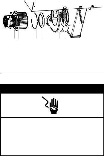
7.Reattach the four #10-32 locknuts to secure the blower motor assembly back to the blower exhaust scroll.
A B C D E F
A.#10 - 32 locknut
B.Blower motor and wheel assembly
C.Retainer
D.Restrictor ring
E.Exhaust scroll
F. Blower wheel guard
Electrical Requirements
 WARNING
Electrical Shock Hazard
Disconnect power before servicing.
Use 8 gauge copper wire.
Electrically ground cooktop.
Failure to follow these instructions can result in death, fire, or electrical shock.
If codes permit and a separate ground wire is used, it is recommended that a qualified electrical installer determine that the ground path and wire gauge are in accordance with local codes.
Check with a qualified electrical installer if you are not sure the cooktop is properly grounded.
Make sure that the electrical connection and wire size are adequate and in conformance with the National Electrical Code, ANSI/NFPA 70-latest edition or CSA Standards C22.1-94, Canadian Electrical Code, Part 1 and C22.2 No. O-M91-latest edition, and all local codes and ordinances.
A copy of the above code standards can be obtained from:
National Fire Protection Association One Batterymarch Park
Quincy, MA 02269
CSA International
8501 East Pleasant Valley Road Cleveland, OH 44131-5575
Before You Make the Electrical Connection:
To properly install your cooktop, you must determine the type of electrical connection you will be using and follow the instructions provided for it here.
■A 4-wire or 3-wire, single phase, 120/240 volt, 60 Hz., AC only electrical supply on a separate, 40-amp circuit breaker is required for both 30" (76.2 cm) and 36" (91.4 cm) models. If a fused system is used, fuse both sides of the line.
■The cooktop should be connected directly to the junction box through the flexible metal conduit. The flexible, armored cable extending from the fuse box or circuit breaker box should be connected directly to the junction box.
■Locate the junction box to allow as much slack as possible between the junction box and the cooktop so that the cooktop can be moved if servicing becomes necessary in the future.
■A UL listed or CSA approved conduit connector must be provided at each end of the power supply cable (at the cooktop and at the junction box).
■If the house has aluminum wiring follow the procedure below:
1.Connect a section of solid copper wire to the pigtail leads.
2.Connect the aluminum wiring to the added section of copper wire using special connectors and/or tools designed and UL listed for joining copper to aluminum.
Follow the electrical connector manufacturer's recommended procedure. Aluminum/copper connection must conform with local codes and industry accepted wiring practices.
8
 Loading...