


30" (76.2 CM) AND 36" (91.4 CM) ELECTRIC
DOWNDRAFT COOKTOP
INSTALLATION INSTRUCTIONS
INSTRUCTIONS D'INSTALLATION DE LA TABLE DE
CUISSON ÉLECTRIQUE AVEC ASPIRATION
PAR LE BAS DE 30" (76,2 CM) ET 36" (91,4 CM)
Table of Contents/Table des matières
COOKTOP SAFETY........................................................................2
INSTALLATION REQUIREMENTS ................................................3
Tools and Parts ............................................................................3
Location Requirements ................................................................3
Venting Requirements..................................................................5
Venting Methods ..........................................................................6
Electrical Requirements ..............................................................8
INSTALLATION INSTRUCTIONS ..................................................9
Prepare Cooktop..........................................................................9
Install Foam Strip..........................................................................9
Rotate Blower - Optional..............................................................9
Install Cooktop ...........................................................................11
Make Electrical Connection .......................................................11
Complete Installation..................................................................12
SÉCURITÉ DE LA TABLE DE CUISSON .................................13
EXIGENCES D'INSTALLATION................................................14
Outils et pièces........................................................................14
Exigences d’emplacement...................................................... 14
Exigences concernant l'évacuation ........................................16
Méthodes d'évacuation...........................................................17
Spécifications électriques ....................................................... 19
INSTRUCTIONS D’INSTALLATION .........................................20
Préparation de la table de cuisson .........................................20
Installation de la bande de mousse........................................20
Rotation du ventilateur - Facultative.......................................20
Installation de la table de cuisson...........................................22
Raccordement électrique........................................................22
Achever l'installation ...............................................................23
IMPORTANT:
Save for local electrical inspector's use.
IMPORTANT :
À conserver pour consultation par l'inspecteur local des installations électriques.
W10298568A
COOKTOP SAFETY
Your safety and the safety of others are very important.
We have provided many important safety messages in this manual and on your appliance. Always read and obey all safety
messages.
This is the safety alert symbol.
This symbol alerts you to potential hazards that can kill or hurt you and others.
All safety messages will follow the safety alert symbol and either the word “DANGER” or “WARNING.”
These words mean:
You can be killed or seriously injured if you don't immediately
DANGER
WARNING
All safety messages will tell you what the potential hazard is, tell you how to reduce the chance of injury, and tell you what can
happen if the instructions are not followed.
follow instructions.
can be killed or seriously injured if you don't
You
instructions.
follow
2
INSTALLATION REQUIREMENTS
Tools and Parts
Gather the required tools and parts before starting installation.
Read and follow the instructions provided with any tools listed
here.
Tools ne eded
■ Tape measure
■ Flat-blade screwdriver
■ Phillips head screwdriver
■ Drill
■ Level
■ 6" socket extension
Parts supplied
■ Vent grille
■ Pre-filter
Parts needed
■ A UL listed or CSA approved strain relief for ⁷⁄₈" (2.2 cm)
knockout.
■ A UL listed or CSA approved conduit connector for
¹⁄₂" (1.3 cm) trade-size metal-clad conduit
■ UL listed wire connectors
■ Metal ducting
■ Wall cap
6" (15.2 cm) Round Surface Wall Cap Damper
Order Part Number A406
5" (12.7 cm) Round Surface Wall Cap Damper
Order Part Number A405
3¼" x 10" (8.3 x 25.4 cm) Surface Wall Cap Damper
Order Part Number A403
To order, see the “Assistance or Service” section of the Use
and Care Guide.
■ Vent clamps
Check local codes. Check existing electrical supply. See
“Electrical Requirements” section.
It is recommended that all electrical connections be made by a
licensed, qualified electrical installer.
Location Requirements
IMPORTANT: Observe all governing codes and ordinances.
When installing cooktop, use minimum dimensions given.
■ To eliminate the risk of burns or fire by reaching over the
heated surface units, cabinet storage space located above
the surface units should be avoided. If cabinet storage is to
be provided, the risk can be reduced by installing a range
hood that projects horizontally a minimum of 5" (12.7 cm)
beyond the bottom of the cabinets.
■ Use the countertop opening dimensions that are given with
these Installation Instructions. Given dimensions are
minimum clearances and provide 0" (0 cm) clearance.
■ Marker or pencil
■ Pliers
■ ¼" drill bit
■ Jigsaw
■ Ratchet with ³⁄₈"socket
■ Grounded electrical supply is required. See “Electrical
Requirements” section.
■ If cabinet has drawers, drawers will need to be removed and
drawer fronts installed on front of cabinet.
IMPORTANT: An under-counter built-in oven cannot be installed
under this product.
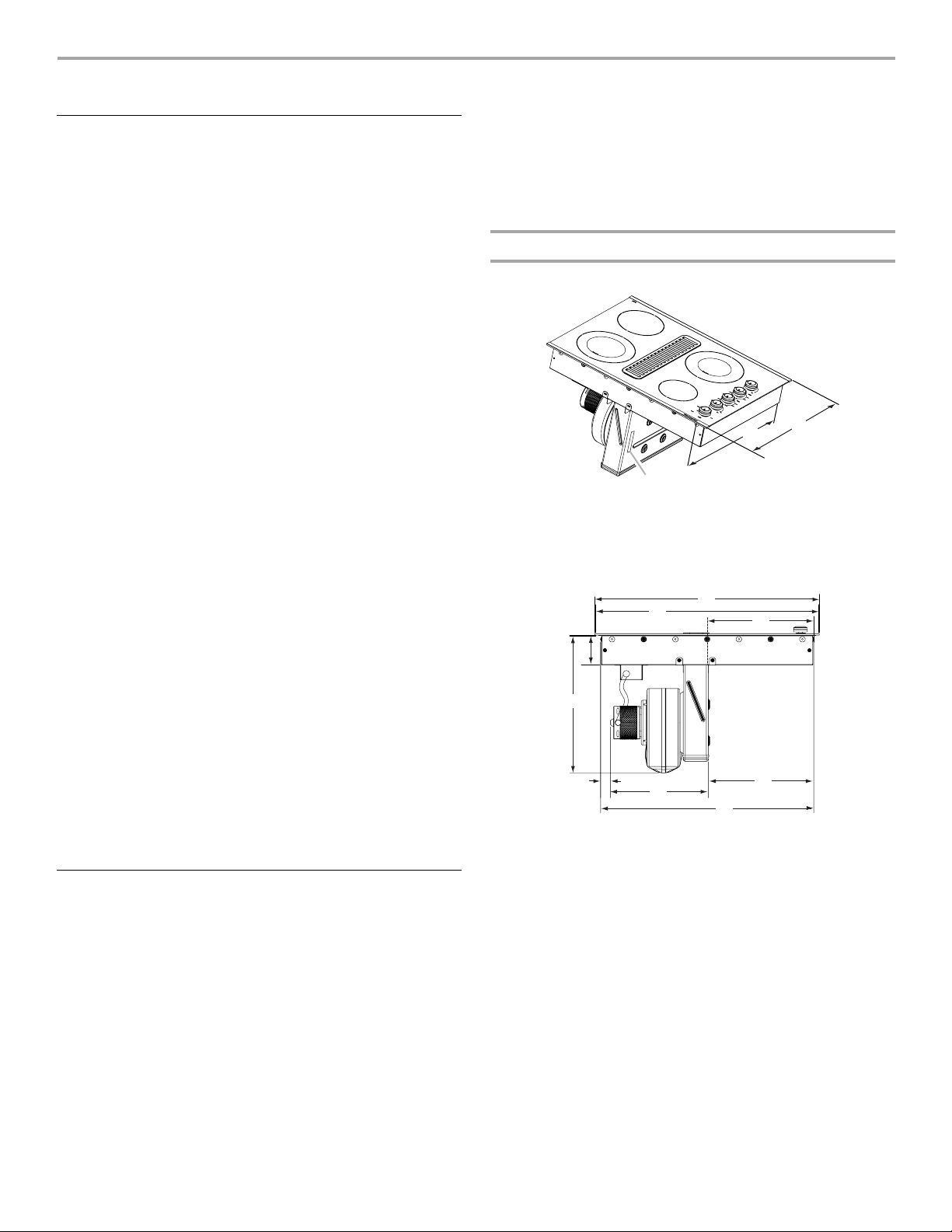
Product Dimensions
30" (76.2 cm) Cooktop - for standard and electric models
B
A
A. Model/serial rating/clearance plate location
B. 21" (53.4 cm) screw head to screw head
C. 22" (52.3 cm) without stainless steel trim or
21³⁷⁄₆₄" (54.8 cm) with stainless steel trim
A
B
D
E
F
G
I
A. 30¹⁄₃₂" (76.3 cm) with stainless steel trim
B. 29¹⁵⁄₁₆" (76.1 cm) without stainless steel trim
C. 14⁵⁄₁₆" (36.4 cm)
D. 3³¹⁄₃₂" (10.1 cm)
E. 18¹³⁄₃₂" (46.8 cm)
F. 1 ¹¹⁄₃₂" (3.4 cm)
G. 13³⁄₃₂" (33.3 cm)
H. 14³⁄₁₆" (36.0 cm)
I. 28⁵⁄₈" (72.7 cm) screw head to screw head
C
C
H
3

36" (91.4 cm) Cooktop - for standard and electric models
Cabinet Dimensions
A
D
C
C
B
B
G
A
A. Model/serial rating/clearance plate location
B. 21" (53.4 cm) screw head to screw head
C. 22" (52.3 cm) without stainless steel trim or
21³⁷⁄₆₄" (54.8 cm) with stainless steel trim
L
F
E
H
I
K
J
A
B
C
A. 30" (76.2 cm) on 30" (76.2 cm) models
D
E
F
G
H
I
A. 35²⁹⁄₆₄" (90.1 cm) with stainless steel trim
B. 35²⁵⁄₆₄" (89.9 cm) without stainless steel trim
C. 17³¹⁄₆₄" (43.8 cm)
D. 3²⁵⁄₃₂" (9.6 cm)
E. 18¹³⁄₃₂" (46.8 cm)
F. 8 ¹⁷⁄₆₄" (20.9 cm)
G. 13³⁄₃₂" (33.3 cm)
H. 13¹⁄₁₆" (33.2 cm)
I. 34³¹⁄₆₄" (87.6 cm) screw head to screw head
36" (91.4 cm) on 36" (91.4 cm) models
B. Combustible area above countertop (shown by dashed box above)
C. 30" (76.2 cm) minimum clearance between top of cooktop platform
and bottom of uncovered wood or metal cabinet (24" [61 cm]
minimum clearance if bottom of wood or metal cabinet is covered
by not less than ¹⁄₄" [0.6 cm] flame retardant millboard covered with
not less than No. 28 MSG sheet steel, 0.015" [0.04 cm] stainless
steel, or 0.024" [0.06 cm] aluminum or 0.020" [0.05 cm] copper)
D. 13" (33 cm) recommended upper cabinet depth
E. 2" (5.1 cm)
F. 2 1 ¹⁄₈" (73.4 cm)
G. 18" (45.7 cm) minimum clearance from upper cabinet to countertop
within minimum horizontal clearances to cooktop
H. Junction box or outlet; 12" (30.5 cm) minimum from bottom of
countertop
I. Junction box or outlet; 10" (25.4 cm) from right-hand side of
cabinet
J. 28⁷⁄₈" (73.4 cm) on 30" (76.2 cm) models
34⁹⁄₁₆" (87.8 cm) on 36" (91.4 cm) models
K. 2½" (6.4 cm) minimum distance to nearest left and right side
combustible surface above cooktop
L. 1½" (3.8 cm) minimum clearance between back wall and
countertop
NOTES: After making the countertop cutout, some installations
may require notching down the base cabinet side walls to clear
the cooktop base. To avoid this modification, use a base cabinet
with sidewalls wider than the cutout.
■ A minimum side clearance of 6" (15.2 cm) is recommended
between side of cooktop and side wall for maximum
ventilation performance.
■ A minimum clearance of 2" (5.1 cm) is recommended
between the motor/blower and cabinet for proper cooling. A
6" (15.2 cm) clearance is recommended for servicing access.
4

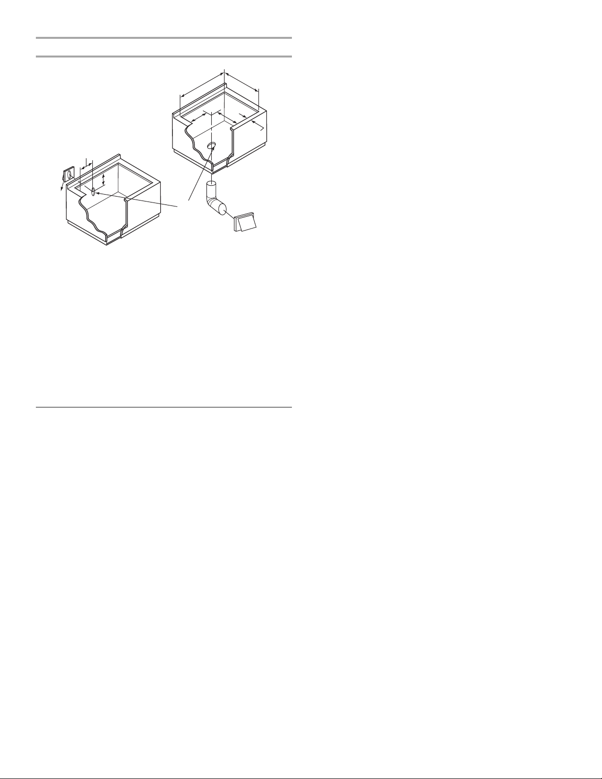
Cutout Dimensions
A
C
H
I
J
G
A. 28⁷⁄₈" (73.4 cm) maximum on 30" (76.2 cm) models
34⁹⁄₁₆" (87.8 cm) maximum on 36" (91.4 cm) models
B. 21¹⁄₈" (53.7 cm) maximum on both 30" (76.2 cm) and 36" (91.4 cm)
models
C. 8¹⁹⁄₃₂" (21.8 cm) on 30" (76.2 cm) models
15⁷⁄₁₆" (39.2 cm) on 36" (91.4 cm) models
D. 6¹⁹⁄₆₄" (16.0 cm) on both 30" (76.2 cm) and 36" (91.4 cm) models
E. 2" (5.1 cm) minimum space to front edge of cooktop
F. Floor exhaust option
G. 6¹⁄₈" (15.6 cm) for 6" (15.2 cm) vent system
5¹⁄₈" (13 cm) for 5" (12.7 cm) vent system
H. 8¹⁹⁄₃₂" (21.8 cm) on 30" (76.2 cm) models
15⁷⁄₁₆" (39.2 cm) on 36" (91.4 cm) models
I. 16" (40.6 cm) on both 30" (76.2 cm) and 36" (91.4 cm) models
J. Wall exhaust option
B
D
E
F
Venting Requirements
IMPORTANT: This cooktop must be exhausted outdoors.
■ Do not terminate the vent system in an attic or other enclosed
area.
■ Use a vent cap.
■ Vent system must terminate to the outside.
■ Use only a 6" (15.2 cm) diameter round or 3¼" x 10"
(8.3 x 25.4 cm) rectangular vent except as follows: For
electric cooktops, a 5" (12.7 cm) diameter round vent may be
used for venting straight out the back of the cooktop and
directly through the wall for 10 ft (3.0 m) or less.
■ Before making cutouts, make sure there is proper clearance
within the wall or floor for the exhaust vent.
■ Do not cut a joist or stud unless absolutely necessary. If a
joist or stud must be cut, then a supporting frame must be
constructed.
■ The size of the vent should be uniform.
■ The vent system must have a damper. If roof or wall cap has a
damper, do not use damper supplied with the range hood.
■ Use vent clamps to seal all joints in the vent system.
■ Use caulking to seal exterior wall or roof opening around the
cap.
■ Determine which venting method is best for your application.
For Best Performance:
■ Use 26-gauge minimum galvanized or 25-gauge minimum
aluminum metal vent. Poor quality pipe fittings can reduce
airflow. Flexible metal vent is not recommended.
NOTE: Local codes may require a heavier gauge material.
■ Metal duct may be reduced to 30-gauge galvanized steel or
26-gauge aluminized steel if allowed by local codes. This
reduction is based on information in the International
Residential Codes Section M1601.1 (2006 edition).
■ Do not install 2 elbows together.
■ Use no more than three 90° elbows.
■ If an elbow is used, install it as far away as possible from the
hood’s vent motor exhaust opening.
■ Make sure there is a minimum of 18" (45.7 cm) of straight
vent between the elbows if more than one elbow is used.
■ Elbows too close together can cause excess turbulence that
reduces airflow.
■ Do not use a 5" (12.7 cm) elbow in a 6" (15.2 cm) or 3¹⁄₄" x 10"
(8.3 x 25.4 cm) system.
■ Do not reduce to a 5" (12.7 cm) system after using
6" (15.2 cm) or 3¹⁄₄" x 10" (8.3 x 25.4 cm) fittings.
■ Avoid forming handmade crimps. Handmade crimps may
restrict airflow.
■ Use a vent cap for proper performance. If an alternate wall or
roof cap is used, be certain the cap size is not reduced and
that it has a back draft damper.
■ Use vent clamps to seal all joints in the vent system.
■ Use caulking to seal exterior wall or roof opening around the
cap.
The length of vent system and number of elbows should be kept
to a minimum to provide efficient performance.
The maximum equivalent length of the vent system is 60 ft
(18.3 m). For altitudes above 4,500 ft (1272 m), reduce
recommended vent run by 20% for best performance.
Cold Weather Installations
An additional back draft damper should be installed to minimize
backward cold air flow and a thermal break installed to minimize
conduction of outside temperatures as part of the vent system.
The damper should be on the cold air side of the thermal break.
Makeup Air
Local building codes may require the use of makeup air systems
when using ventilation systems greater than specified CFM of air
movement. The specified CFM varies from locale to locale.
Consult your HVAC professional for specific requirements in your
area.
5
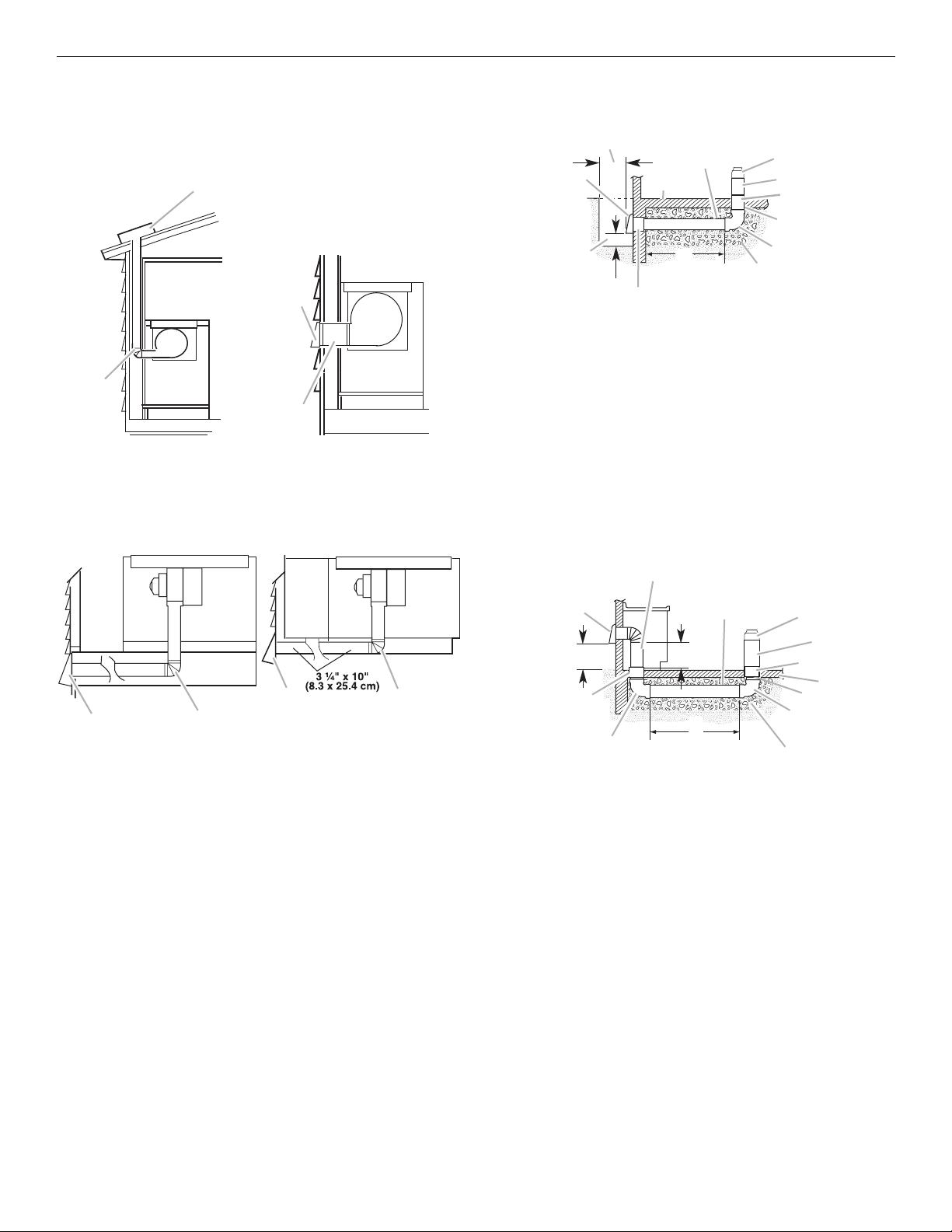
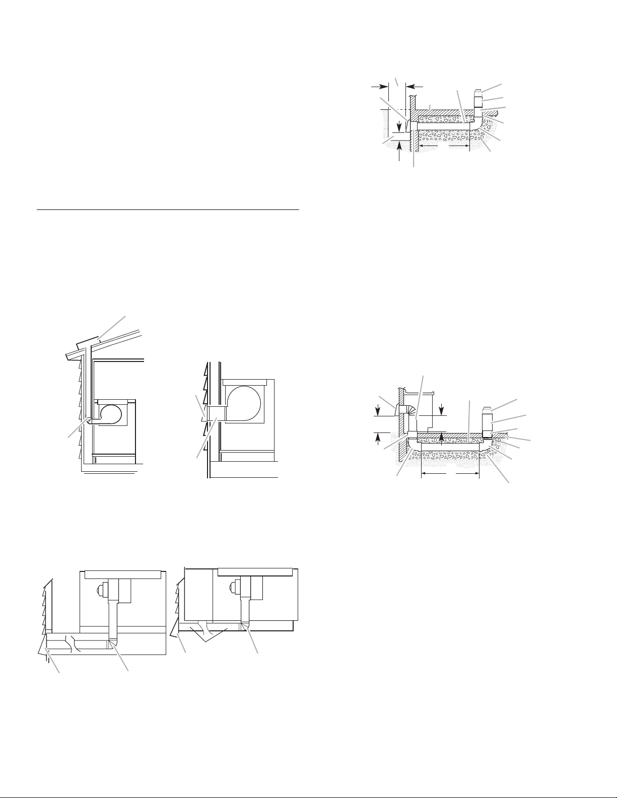
Venting Methods
Common venting methods are shown for a counter-mounted
downdraft cooktop. The cooktop may be vented through the wall
or floor.
Option 1 - Roof Venting Option 2 - Wall Venting
B
B
A
A
A. Roof cap
B. 6" (15.2 cm) round roof
venting
Option 3 - Venting Between
Floor Joist
A. 6" (15.2 cm) round wall
venting
B. Wall cap
Option 4 - Venting behind
Cabinet Kick Plate
Concrete Slab Installations Exhaust Through Window Well
B
D
A
C
E
F
G
H
N
M
A. Wall cap
B. 12" (30.5 cm) minimum
C. Concrete slab
D. 6" (15.2 cm) round PVC sewer pipe
E. 5" to 6" (12.7 cm to 15.2 cm) transition
F. 6" (15.2 cm) round metal duct
G. 6" (15.2 cm) round PVC coupling
H. 6" (15.2 cm) round PVC sewer pipe
I. 6" (15.2 cm) round 90° PVC sewer pipe elbow
J. Tightly pack gravel or sand completely around pipe.
K. 42 ft (12.8 m) max.
L. 6" (15.2 cm) round PVC coupling
M. 6" (15.2 cm) minimum
N. Window well
K
L
I
J
Concrete Slab Installations - Exhaust Through Wall
B
A
A. Wall cap
B. 6" (15.2 cm) round wall
venting
B
A
A. Wall cap
B. 6" (15.2 cm) round wall
venting
B
A
O
N
M
A. Wall cap
B. 6" (15.2 cm) round metal vent
C. 16" (40.6 cm) maximum
D. 6" (15.2 cm) round PVC sewer pipe
E. 5" to 6" (12.7 cm to 15.2 cm) transition
F. 6" (15.2 cm) round metal duct
G. 6" (15.2 cm) round PVC coupling
H. Concrete slab
I. 6" (15.2 cm) round PVC sewer pipe
J. 6" (15.2 cm) round 90° PVC sewer pipe elbow
K. Tightly pack gravel or sand completely around pipe.
L. 30 ft (9.1 m) max.
M. 6" (15.2 cm) round 90° PVC sewer pipe elbow
N. 6" (15.2 cm) round PVC coupling
O. 12" (30.5 cm) minimum
C
L
D
E
F
G
H
I
J
K
6
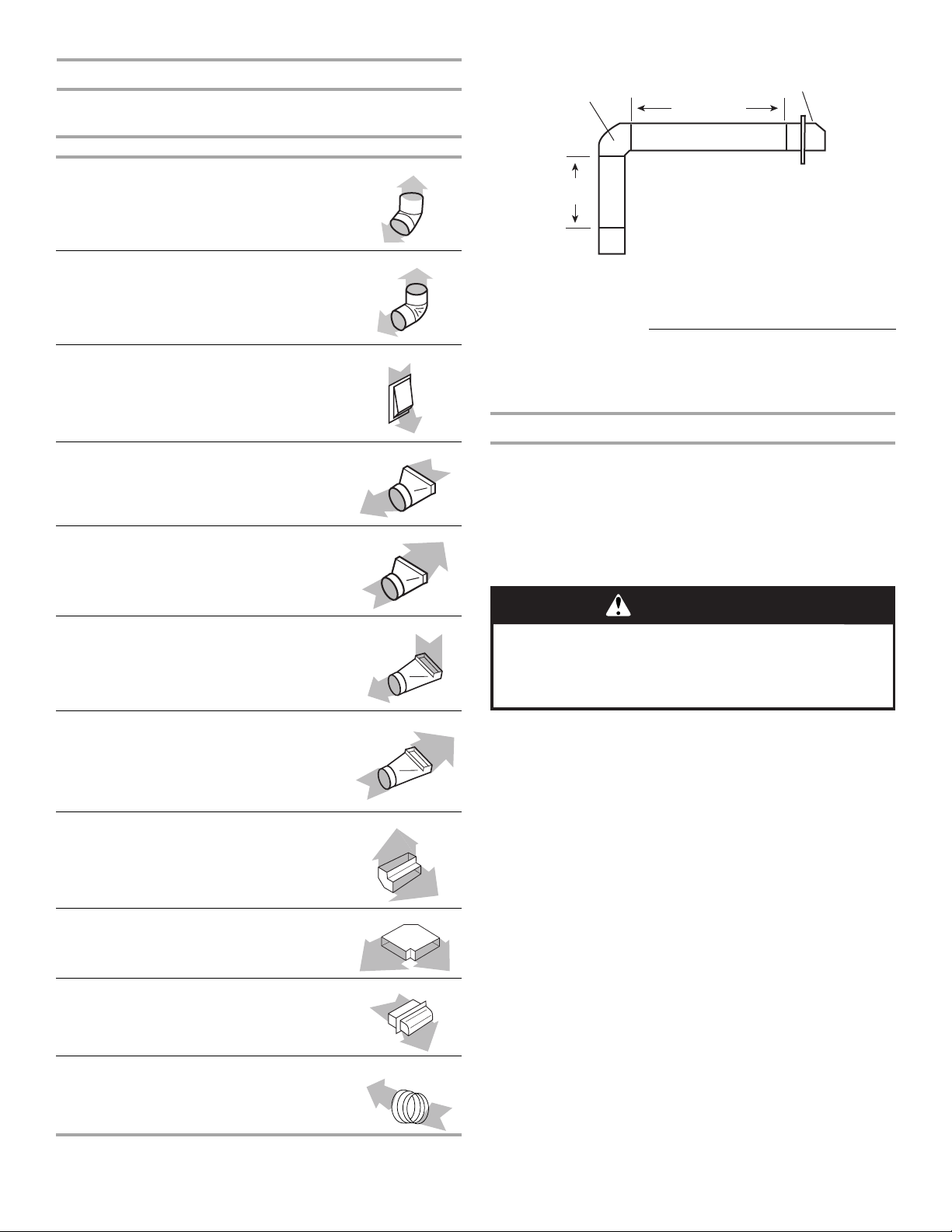
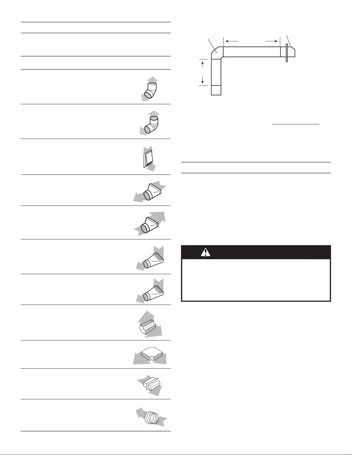
Calculating Vent System Length
To calculate the length of the system you need, add the
equivalent feet (meters) for each vent piece used in the system.
Vent Piece 6" (15.2 cm) Round
Example vent system
90˚ elbow
wall cap
6 ft (1.8 m)
45° elbow 2.5 ft
90° elbow 5.0 ft
6" (15.2 cm)
wall cap
3¹⁄₄" x 10" (8.3 cm x 25.4 cm)
to 6" (15.2 cm) transition
6" (15.2 cm) to 3¹⁄₄" x 10"
(8.3 cm x 25.4 cm) transition
(0.8 m)
(1.5 m)
0.0 ft
(0.0 m)
4.5 ft
(1.4 m)
1 ft
(0.3 m)
2 ft
(0.6 m)
1- 90° elbow = 5 ft (1.5 m)
8 ft (2.4 m) straight = 8 ft (2.4 m)
1 - wall cap = 0 ft (0 m)
System length = 13 ft (3.9 m)
NOTE: Flexible vent is not recommended. Flexible vent creates
back pressure and air turbulence that greatly reduce
performance.
Determine Range Blower Setting
This cooktop is equipped with a dual range blower. It is shipped
from the factory in the low range for most installations. If the
equivalent duct length exceeds 30 ft (9.1 m), it must be converted
to high range. Do not convert the blower to high range for shorter
lengths; this will cause excessive noise and conditioned air loss.
Convert blower before installing into countertop if necessary.
To Convert to High Range:
WARNING
3¹⁄₄" x 10" (8.3 cm x 25.4 cm)
to 6" (15.2 cm) 90° elbow
transition
6" (15.2 cm) to 3¹⁄₄" x 10"
(8.3 cm x 25.4 cm) 90° elbow
transition
3¹⁄₄" x 10" (8.3 cm x 25.4 cm)
90° elbow
3¹⁄₄" x 10" (8.3 cm x 25.4 cm)
flat elbow
3¹⁄₄" x 10" (8.3 cm x 25.4 cm)
wall cap
5" to 6" (12.7 cm to 15.2 cm)
transition
9.0 ft
(2.7 m)
5.0 ft
(1.5 m)
5.0 ft
(1.5 m)
12.0 ft
(3.7 m)
0.0 ft
(0.0 m)
1 ft
(0.3 m)
Excessive Weight Hazard
Use two or more people to move and install cooktop.
Failure to do so can result in back or other injury.
1. Using 2 or more people, place cooktop on floor with front
edge and plenum down.
2. Remove the four #10 - 32 locknuts (A) that attach the blower
motor assembly to the blower exhaust scroll.
3. Remove the blower motor assembly (B) from the blower
exhaust scroll (E).
4. Slowly reach in the blower exhaust scroll opening and
remove the retainer (C).
5. Gently remove the restrictor ring (D).
6. Place the motor assembly back on the studs of the blower
exhaust scroll.
7
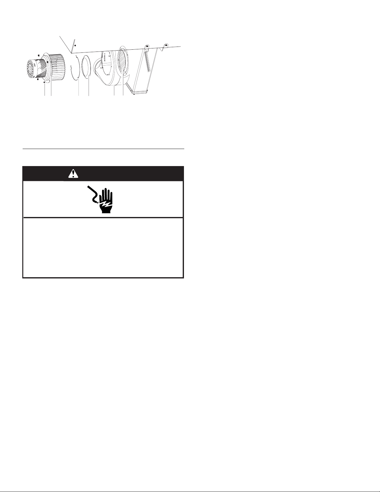
7. Reattach the four #10-32 locknuts to secure the blower motor
assembly back to the blower exhaust scroll.
B
A
C
D
A. #10 - 32 locknut
B. Blower motor and wheel assembly
C.Retainer
D. Restrictor ring
E. Exhaust scroll
F. Blower wheel guard
E
F
Electrical Requirements
WARNING
Before You Make the Electrical Connection:
To properly install your cooktop, you must determine the type of
electrical connection you will be using and follow the instructions
provided for it here.
■ A 4-wire or 3-wire, single phase, 120/240 volt, 60 Hz., AC
only electrical supply on a separate, 40-amp circuit breaker is
required for both 30" (76.2 cm) and 36" (91.4 cm) models. If a
fused system is used, fuse both sides of the line.
■ The cooktop should be connected directly to the junction box
through the flexible metal conduit. The flexible, armored cable
extending from the fuse box or circuit breaker box should be
connected directly to the junction box.
■ Locate the junction box to allow as much slack as possible
between the junction box and the cooktop so that the
cooktop can be moved if servicing becomes necessary in the
future.
■ A UL listed or CSA approved conduit connector must be
provided at each end of the power supply cable (at the
cooktop and at the junction box).
■ If the house has aluminum wiring follow the procedure below:
1. Connect a section of solid copper wire to the pigtail
leads.
2. Connect the aluminum wiring to the added section of
copper wire using special connectors and/or tools
designed and UL listed for joining copper to aluminum.
Follow the electrical connector manufacturer's recommended
procedure. Aluminum/copper connection must conform with
local codes and industry accepted wiring practices.
Electrical Shock Hazard
Disconnect power before servicing.
Use 8 gauge copper wire.
Electrically ground cooktop.
Failure to follow these instructions can result in death,
fire, or electrical shock.
If codes permit and a separate ground wire is used, it is
recommended that a qualified electrical installer determine that
the ground path and wire gauge are in accordance with local
codes.
Check with a qualified electrical installer if you are not sure the
cooktop is properly grounded.
Make sure that the electrical connection and wire size are
adequate and in conformance with the National Electrical Code,
ANSI/NFPA 70-latest edition or CSA Standards C22.1-94,
Canadian Electrical Code, Part 1 and C22.2 No. O-M91-latest
edition, and all local codes and ordinances.
A copy of the above code standards can be obtained from:
National Fire Protection Association
One Batterymarch Park
Quincy, MA 02269
CSA International
8501 East Pleasant Valley Road
Cleveland, OH 44131-5575
8

INSTALLATION INSTRUCTIONS
C
C
Prepare Cooktop
Decide on the final location for the cooktop.
WARNING
Excessive Weight Hazard
Use two or more people to move and install cooktop.
Failure to do so can result in back or other injury.
1. Open product as instructed on product packaging.
2. Remove shipping materials and tape from cooktop.
3. Remove vent grille.
A
B
D
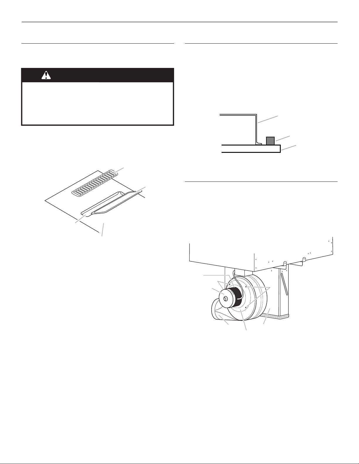
Install Foam Strip
1. Remove foam strip from the package containing literature.
2. Remove backing from foam strip.
3. Apply foam strip adhesive-side down around bottom of
cooktop, flush with edge.
NOTE: The foam strip keeps the underside of the cooktop
glass free from debris and helps the cooktop sit flat on
uneven counters.
A
B
A. Cooktop base
B. Foam strip
C. Glass
Rotate Blower - Optional
IMPORTANT: The following additional steps must be performed
if the product is being installed in peninsula or island cabinetry.
The blower exhaust scroll is shipped from the factory set to
exhaust straight out the back of the cabinet through an exterior
wall.
A. Vent grille
B. Plenum
C. Removable grease filter
D. Ceramic glass top
4. Remove the removable grease filter by lifting the filter out.
5. Using 2 or more people, remove the cooktop from the carton.
6. Use foam end caps from the packaging as a work surface for
the floor or countertop.
7. Using 2 or more people, place the cooktop upside down on
the foam end caps.
8. Make sure knobs are positioned in the open areas of the end
caps.
9. Avoid placing the cooktop facedown on the control knobs.
D
E
C
A
F
A. Blower exhaust scroll
B. Plenum
C. Blower motor
D. Top label
E. 10-32 machine nuts (4)
F. Motor mounting plate
E
B
9

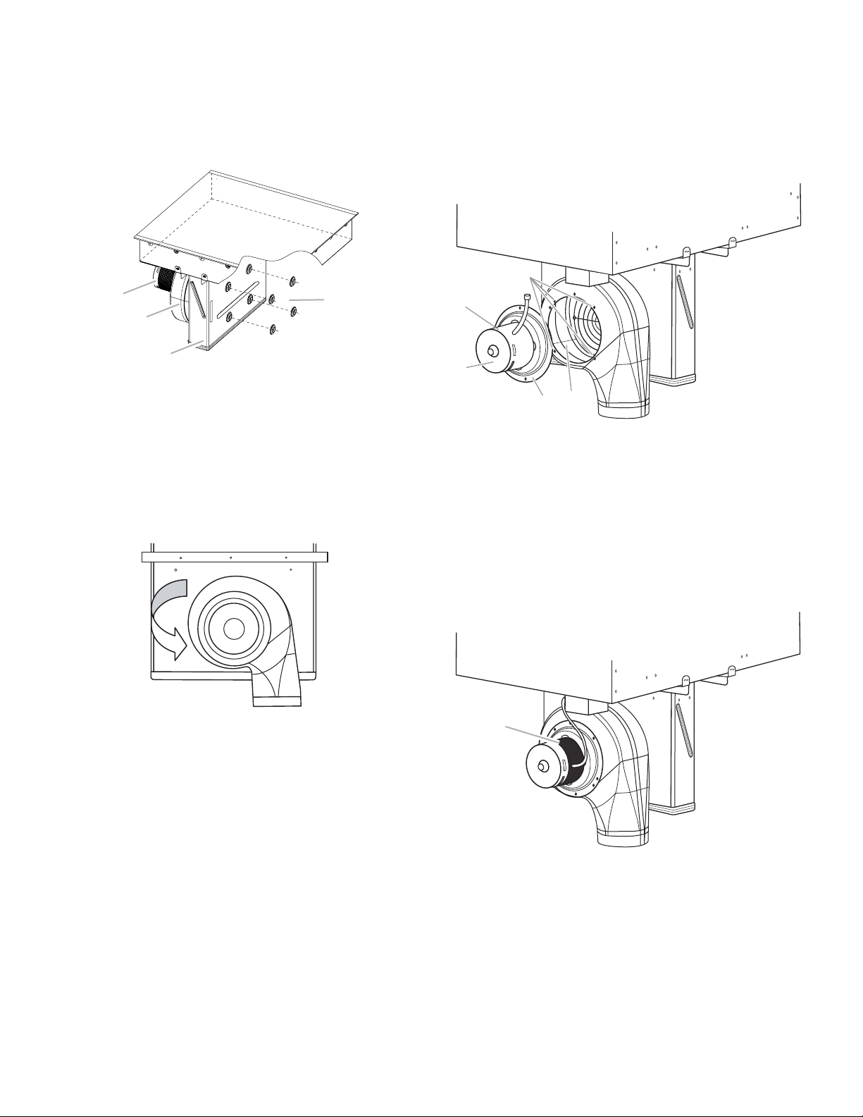
To rotate blower:
1. Locate the four plastic plugs in the plenum bypass.
2. Use the pliers to remove the plastic plugs.
IMPORTANT: Do not throw away the plastic plugs. The
plastic plugs must be reinstalled after the blower exhaust
scroll has been rotated.
To rotate blower motor:
NOTE: The “Top” label location on the blower motor is at the
9 o’clock position.
1. Using a ratchet with a ³⁄₈" socket and supporting the motor
with one hand, remove the four machine nuts that attach the
blower motor to the exhaust scroll.
2. Remove the blower motor and wheel assembly from the weld
studs.
A
D
B
C
A. Blower motor
B. Exhaust scroll
C. Plenum
D. Plastic plugs (4)
3. Insert the ³⁄₈" socket and extension into the hole and use the
ratchet handle to loosen the nut half of a rotation. Repeat this
process for each of the four nuts.
4. With the nuts loosened, the blower exhaust scroll can be
easily rotated downward.
D
A
B
E
C
A. Top label
B. Blower motor
C. Motor mounting plate
D. Weld stud location
E. Blower wheel
3. When the motor mounting plate clears the threaded weld
studs, rotate the assembly clockwise 90° and reinstall the
four #10-32 machine nuts.
4. Verify the “Top” label is positioned as shown.
5. Retighten each nut with the ³⁄₈" socket, extension and ratchet.
6. Reinstall the four plastic plugs.
10
A
A. Top label

Install Cooktop
G
1. Using 2 or more people, place cooktop right side up into the
cutout.
NOTE: Make sure that the front edge of the cooktop is
parallel to the front edge of the countertop. If repositioning is
needed, lift entire cooktop up from the cutout to avoid
scratching the countertop.
2. For island or peninsula installations, go to “Rotate Blower Optional” section.
3. Connect blower exhaust scroll to ducting.
4. Use vent clamps to secure the ducting to the blower exhaust
scroll.
5. Reinstall removable grease filter.
6. Reinstall vent grille.
Electrical Connection Options
If your home has: And you will be
4-wire A fused
½"
(1.3 cm)
3-wire A fused
connecting to:
disconnect or
circuit breaker
box
disconnect or
circuit breaker
box
Go to Section:
4-Wire Cable from
Power Supply
3-Wire Cable from
Power Supply
Make Electrical Connection
WARNING
Electrical Shock Hazard
Disconnect power before servicing.
Use 8 gauge copper wire.
Electrically ground cooktop.
Failure to follow these instructions can result in death,
fire, or electrical shock.
This cooktop is manufactured with the frame connected to the
bare ground wire. Connect the cooktop cable to the junction box
through the UL listed or CSA approved conduit connector.
1. Disconnect power.
2. Remove junction box cover, if present.
3. Connect the flexible cable conduit from the cooktop to the
junction box using a UL listed or CSA approved conduit
connector.
4. Tighten screws on conduit connector if present.
5. See “Electrical Connection Options Chart” to complete
installation for your type of electrical connection.
½"
(1.3 cm)
4-Wire Cable from Home Power Supply to 4-Wire Cable
from Cooktop
IMPORTANT: Use the 4-wire cable from home power supply in
the U.S. where local codes do not allow grounding through
neutral, New Branch circuit installations (1996 NEC), mobile
homes and recreational vehicles, new construction, and in
Canada.
A
B
C
D
A. Cable from home power supply
B. Black wires
C. Bare ground wires
D. 4-wire cable from cooktop
E. Junction box
1. Connect the 2 black wires together using the UL listed wire
connectors.
2. Connect the 2 red wires together using the UL listed wire
connectors.
3. Connect the 2 white wires together using the UL listed wire
connectors.
4. Connect the green (or bare) ground wire from the cooktop
cable to the green (or bare) ground wire (in the junction box)
using the UL listed wire connectors.
5. Install junction box cover.
F. W h i t e w ires
G. UL listed wire connector
H. Red wires
I. UL listed or CSA approved
conduit connector
E
F
H
I
11

3-Wire Cable from Home Power Supply to 4-Wire Cable
G
from Cooktop - U.S. only
IMPORTANT: Use the 3-wire cable from power supply where
local codes permit connecting the frame-ground conductor to
the neutral (white) junction box wire.
A
B
C
D
E
F
H
I
Complete Installation
1. Check that all parts are now installed. If there is an extra part,
go back through the steps to see which step was skipped.
2. Check that you have all your tools.
3. Dispose of/recycle all packaging materials.
4. Use a mild solution of liquid household cleaner and warm
water to clean cooktop before use. Dry thoroughly with a soft
cloth. For more information, see the “Cooktop Care” section
of the Use and Care Guide.
5. Read “Cooktop Use” in the cooktop Use and Care Guide.
6. Reconnect power.
7. Use the Flow Tester Card provided with your cooktop to
check the airflow (see card for step-by-step instructions).
NOTE: If the cooktop does not work after turning on the power,
check that a circuit breaker has not tripped or a household fuse
has not blown. See “Troubleshooting” section in the Use and
Care Guide for further information.
A. Cable from home power supply
B. Red wires
C. White wire and green (or bare)
wire (from cooktop)
D. 4-wire cable from cooktop
E. Junction box
F. White wire
G. UL listed wire connector
H. Black wires
I. UL listed or CSA approved
conduit connector
1. Connect the 2 black wires together using the UL listed wire
connectors.
2. Connect the 2 red wires together using the UL listed wire
connectors.
3. Connect the green or bare and white cooktop cable wires to
the white (neutral) wire in the junction box using the UL listed
wire connectors.
4. Install junction box cover.
If you need Assistance or Service:
Please reference the “Assistance or Service” section of the Use
and Care Guide or contact the dealer from whom you purchased
your cooktop.
12

SÉCURITÉ DE LA TABLE DE CUISSON
Votre sécurité et celle des autres est très importante.
Nous donnons de nombreux messages de sécurité importants dans ce manuel et sur votre appareil ménager. Assurez-vous de
toujours lire tous les messages de sécurité et de vous y conformer.
Voici le symbole d’alerte de sécurité.
Ce symbole d’alerte de sécurité vous signale les dangers potentiels de décès et de blessures graves à vous
et à d’autres.
Tous les messages de sécurité suivront le symbole d’alerte de sécurité et le mot “DANGER” ou
“AVERTISSEMENT”. Ces mots signifient :
Risque possible de décès ou de blessure grave si vous ne
DANGER
AVERTISSEMENT
Tous les messages de sécurité vous diront quel est le danger potentiel et vous disent comment réduire le risque de blessure et
ce qui peut se produire en cas de non-respect des instructions.
suivez pas immédiatement les instructions.
Risque possible de décès ou de blessure grave si vous
ne suivez pas les instructions.
13

EXIGENCES D'INSTALLATION
Outils et pièces
Rassembler les outils et pièces nécessaires avant d’entreprendre
l’installation. Lire et suivre les instructions fournies avec chacun
des outils de la liste ci-dessous.
Outils nécessaires
■ Mètre-ruban
■ Tournevis à lame plate
■ Tournevis cruciforme
■ Perceuse
■ Niveau
■ Rallonge pour clé à douille
de 6"
Pièces fournies
■ Grille de ventilation
■ Pré-filtre
Pièces nécessaires
■ Un collier de serrage (homologation UL ou CSA) pour alvéole
défonçable de ⁷⁄₈" (2,2 cm).
■ Un connecteur de conduit (homologation UL ou CSA) pour
conduit de taille commerciale (trade size) de ¹⁄₂"(1,3cm) à
armature métallique
■ Connecteurs de fils (homologation UL)
■ Conduit métallique
■ Bouche de décharge murale
Clapet de bouche de décharge murale à surface arrondie de
6" (15,2 cm)
Commander la pièce numéro A406
Clapet de bouche de décharge murale à surface arrondie de
5" (12,7 cm)
Commander la pièce numéro A405
Clapet de bouche de décharge murale à surface arrondie de
3¼" x 10" (8,3 x 25,4 cm)
Commander la pièce numéro A403
Pour commander, voir la section “Assistance ou service” du
Guide d’utilisation et d’entretien.
■ Bride de conduit
Consulter les codes locaux. Vérifier l’alimentation électrique
existante. Voir la section “Spécifications électriques”.
Il est recommandé de faire réaliser tous les raccordements
électriques par un électricien qualifié agréé.
Exigences d’emplacement
IMPORTANT : Observer les dispositions de tous les codes et
règlements en vigueur. Lors de l’installation de la table de
cuisson, utiliser les dimensions minimales indiquées.
■ Afin de supprimer le risque de brûlures ou d'incendie en se
penchant au-dessus des unités de surface chauffées, le
rangement en armoire au-dessus des unités de surface doit
être évité. Si des placards de rangement sont envisagés, le
risque peut être réduit par l’installation d’une hotte de cuisine
dépassant le bas des placards d’au moins 5" (12,7 cm)
horizontalement.
■ Marqueur ou crayon
■ Pince
■ Foret de ¼”
■ Scie sauteuse
■ Clé à cliquet avec douille de
³⁄₈"
■ Utiliser les dimensions d’ouverture du plan de travail qui sont
indiquées dans ces Instructions d’installation. Les
dimensions données sont les espacements minimaux et
fournissent un dégagement de 0" (0 cm).
■ Une source d’électricité avec liaison à la terre est nécessaire.
Voir la section “Spécifications électriques”.
■ Si le placard comporte des tiroirs, ces tiroirs doivent être
retirés et l'avant des tiroirs installé sur l'avant du placard.
IMPORTANT : Il n'est pas possible d'installer un four encastré
sous plan de travail sous ce produit.
Dimensions du produit
Table de cuisson de 30" (76,2 cm) - Pour les modèles
standard et électriques
B
A
A. Emplacement/dégagement du modèle/de la plaque
signalétique
B. 21" (53,4 cm) d'une tête de vis à l'autre
C. 22" (52,3 cm) sans garniture en acier inoxydable ou
21³⁷⁄₆₄" (54,8 cm) avec garniture en acier inoxydable
A
B
D
E
F
G
I
A. 30¹⁄₃₂" (76,3 cm) avec garniture en acier inoxydable
B. 29¹⁵⁄₁₆" (76,1 cm) sans garniture en acier inoxydable
C. 14⁵⁄₁₆" (36,4 cm)
D. 3³¹⁄₃₂" (10,1 cm)
E. 18¹³⁄₃₂" (46,8 cm)
F. 1 ¹¹⁄₃₂" (3,4 cm)
G. 13³⁄₃₂" (33,3 cm)
H. 14³⁄₁₆" (36,0 cm)
I. 28⁵⁄₈" (72,7 cm) d'une tête de vis à l'autre
C
C
H
14
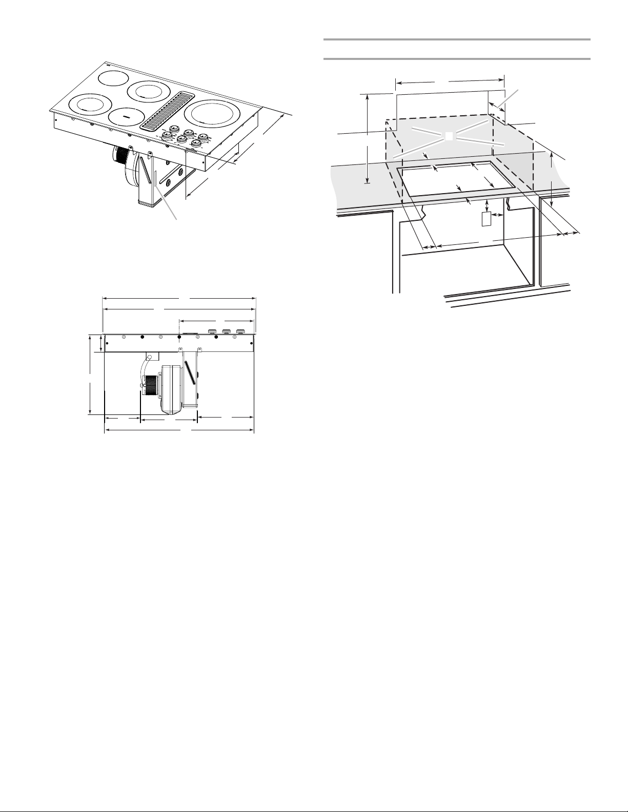
Table de cuisson de 36" (91,4 cm) - Pour les modèles
standard et électriques
Dimensions du placard
C
B
A
A. Emplacement/dégagement du modèle/de la plaque signalétique
B. 21" (53,4 cm) d'une tête de vis à l'autre
C. 22" (52,3 cm) sans garniture en acier inoxydable ou
21³⁷⁄₆₄" (54,8 cm) avec garniture en acier inoxydable
A
B
C
D
E
F
G
H
I
A. 35²⁹⁄₆₄" (90,1 cm) avec garniture en acier inoxydable
B. 35²⁵⁄₆₄" (89,9 cm) sans garniture en acier inoxydable
C. 17³¹⁄₆₄" (43,8 cm)
D. 3²⁵⁄₃₂" (9,6 cm)
E. 18¹³⁄₃₂" (46,8 cm)
F. 8 ¹⁷⁄₆₄" (20,9 cm)
G. 13³⁄₃₂" (33,3 cm)
H. 13¹⁄₁₆" (33,2 cm)
I. 34³¹⁄₆₄" (87,6 cm) d'une tête de vis à l'autre
A
D
C
B
L
F
E
G
H
I
K
A. 30" (76,2 cm) sur les modèles de 30" (76,2 cm)
36" (91,4 cm) sur les modèles de 36" (91,4 cm)
B. Zone de matière combustible au-dessus du plan de travail (espace
délimité par des lignes pointillées ci-dessus)
C. Distance minimale de séparation de 30" (76,2 cm) entre le dessus
de la table de cuisson et le fond d'un placard métallique ou de bois
non couvert (distance de séparation de 24" [61 cm] ou plus si le
fond du placard de métal ou de bois est recouvert d'une plaque
d'au moins ¹⁄₄" (0,6 cm) de matériau résistant aux flammes, luimême recouvert d'une feuille métallique d'une épaisseur
correspondant à un calibre de 28 au moins pour l'acier, 0,015"
[0,04 cm] pour l'acier inoxydable, 0,024" [0,06 cm] pour l'aluminium
ou 0,020" [0,05 cm] pour le cuivre)
D. Profondeur recommandée pour les placards supérieurs : 13"
(33 cm)
E. 2" (5,1 cm)
F. 2 1 ¹⁄₈" (73,4 cm)
G. Distance de séparation minimale de 18" (45,7 cm) entre le placard
supérieur et le plan de travail avec distance minimale de séparation
horizontale pour la table de cuisson
H. Boîtier de connexion ou prise électrique; 12" (30,5 cm) ou plus
depuis le bas du plan de travail
I. Boîtier de connexion ou prise électrique; 10" (25,4 cm) depuis le
côté droit du placard
J. 28⁷⁄₈" (73,4 cm) sur les modèles de 30" (76,2 cm)
34⁹⁄₁₆" (87,8 cm) sur les modèles de 36" (91,4 cm)
K. Distance de séparation minimale de 2½" (6,4 cm) par rapport à la
surface de matériau combustible la plus proche, à gauche ou à
droite au-dessus de la table de cuisson
L. Distance de séparation minimale de 1½" (3,8 cm) ou plus entre la
paroi arrière et le plan de travail
J
REMARQUES : Après le découpage de l'ouverture dans le plan
de travail, il est possible que pour certaines configurations
d'installation, il soit nécessaire d'entailler les parois latérales du
placard inférieur pour permettre le passage de la base de la table
de cuisson. Pour éviter cette modification, utiliser un placard
inférieur dont la largeur des parois latérales est supérieure à celle
de l'ouverture découpée.
■ Un dégagement minimum de 6" (15,2 cm) entre le côté de la
table de cuisson et la paroi latérale est recommandé pour une
performance maximale de ventilation.
■ Un dégagement minimum de 2" (5,1 cm) entre le moteur/
ventilateur et le placard est recommandé pour que le
refroidissement puisse s'effectuer correctement. Un
dégagement de 6" (15,2 cm) est recommandé pour pouvoir
accéder en cas de réparation.
15
Dimensions de l’ouverture à découper
A
C
H
I
J
G
A. 28⁷⁄₈" (73,4 cm) maximum sur les modèles de 30" (76,2 cm)
34⁹⁄₁₆" (87,8 cm) maximum sur les modèles de 36" (91,4 cm)
B. 21¹⁄₈" (53,7 cm) maximum sur les modèles de 30" (76,2 cm) et de
36" (91,4 cm)
C. 8¹⁹⁄₃₂" (21,8 cm) sur les modèles de 30" (76,2 cm)
15⁷⁄₁₆" (39,2 cm) sur les modèles de 36" (91,4 cm)
D. 6¹⁹⁄₆₄" (16,0 cm) sur les modèles de 30" (76,2 cm) et 36" (91,4 cm)
E. Dégagement minimal de 2" (5,1 cm) jusqu'au rebord avant de la
table de cuisson
F. Option d'évacuation par le plancher
G. 6¹⁄₈" (15,6 cm) pour un système d'évacuation de 6" (15,2 cm)
5¹⁄₈" (13 cm) pour un système d'évacuation de 5" (12,7 cm)
H. 8¹⁹⁄₃₂" (21,8 cm) sur les modèles de 30" (76,2 cm)
15⁷⁄₁₆" (39,2 cm) sur les modèles de 36" (91,4 cm)
I. 16" (40,6 cm) sur les modèles de 30" (76,2 cm) et de 36" (91,4 cm)
J. Option d'évacuation par le mur
B
D
E
F
Exigences concernant l'évacuation
IIMPORTANT : L'évacuation de cette table de cuisson doit se
faire à l'extérieur.
■ Ne pas terminer le circuit d'évacuation dans un grenier ou
dans un autre espace fermé.
■ Utiliser un clapet de conduit.
■ Le système doit décharger l'air à l'extérieur.
■ Utiliser uniquement du conduit métallique de 6" (15,2 cm) ou
un conduit d'évacuation rectangulaire de 3¼" x 10" (8,3 x
25,4 cm), sauf dans les cas suivants : avec une cuisinière
électrique, un conduit métallique rond de 5" (12,7 cm) peut
être utilisé pour une évacuation directement depuis l’arrière
de la cuisinière à travers le mur sur une longueur de 10 pi
(3,0 m) au maximum.
■ Avant d'effectuer des découpes, s'assurer qu'il y a un
dégagement convenable entre le mur ou le plancher pour le
conduit d'évacuation.
■ On ne doit couper un poteau de colombage ou une solive
que si c’est absolument nécessaire. Dans ce cas, on devra
construire une structure de support appropriée.
■ La taille du conduit doit être uniforme.
■ Le circuit d'évacuation doit comporter un clapet. Si la bouche
de décharge murale ou par le toit comporte un clapet, ne pas
utiliser le clapet fourni avec la hotte de cuisinière.
■ Au niveau de chaque jointure du circuit d'évacuation, assurer
l'étanchéité avec les brides de serrage.
■ À l'aide d'un produit de calfeutrage, assurer l'étanchéité
autour de la bouche de décharge à l'extérieur (à travers le
mur ou le toit).
■ Déterminer quelle méthode d'évacuation est la plus
appropriée.
Pour obtenir la meilleure performance :
■ Utiliser un conduit de ventilation en acier galvanisé
d'épaisseur minimum nº 26 ou en aluminium d'épaisseur
minimum nº 25. Des raccords de mauvaise qualité peuvent
réduire le flux d'air. On déconseille l’emploi d’un conduit en
métal flexible.
REMARQUE : Les codes locaux pourraient exiger un
matériau plus épais.
■ Le conduit métallique peut être réduit à une épaisseur
nº 30 pour l'acier galvanisé ou nº 26 pour l'aluminium si c'est
permis par les codes locaux. Cette information est basée sur
l'information dans la Section des Codes Résidentiels
Internationaux M1601.1 (édition 2006).
■ Ne pas installer 2 coudes ensemble.
■ Ne pas utiliser plus de trois coudes à 90°.
■ Si l'on utilise un coude, on doit le placer le plus loin possible
de l’ouverture d'évacuation du moteur de la hotte de
ventilation.
■ Veiller à incorporer une section de conduit rectiligne d'au
moins 18" (45,7 cm) entre deux raccords coudés adjacents.
■ Des coudes trop rapprochés peuvent occasionner une
turbulence excessive qui réduirait la circulation de l'air.
■ Ne pas utiliser un coude de 5" (12,7 cm) dans un système de
6" (15,2 cm) ou 3¹⁄₄" x 10" (8,3 x 25,4 cm).
■ Ne pas réduire le système à une longueur de 5" (12,7 cm)
après avoir utilisé des raccords de 6" (15,2 cm) ou de 3¹⁄₄" x
10" (8,3 x 25,4 cm).
■ Éviter le sertissage manuel. Ceux-ci peuvent restreindre le
flux d'air.
■ Utiliser un clapet de conduit pour que le rendement soit
correct. Si une bouche de décharge murale ou de toit est
utilisée, s'assurer que la taille de la bouche de décharge n'est
pas réduite et qu'il a un clapet anti-reflux.
■ Au niveau de chaque jointure du circuit d'évacuation, assurer
l'étanchéité avec les brides de serrage.
■ À l'aide d'un produit de calfeutrage, assurer l'étanchéité
autour de la bouche de décharge à l'extérieur (à travers le
mur ou le toit).
La longueur du système d'évacuation et le nombre de coudes
doit être réduit au minimum pour une performance efficace.
La longueur maximale équivalente du circuit d'évacuation est de
60 pi (18,3 m). Pour les altitudes excédant 4 500 pi (1 272 m),
réduire la longueur du système d'évacuation de 20 % pour une
performance optimale.
16
Installations pour régions à climat froid
On devrait installer un clapet anti-reflux additionnel pour
minimiser le reflux d’air froid, et incorporer un élément d’isolation
thermique pour minimiser la conduction de chaleur par
l’intermédiaire du conduit d’évacuation, de l’intérieur de la
maison à l’extérieur. Le clapet anti-reflux doit être placé du côté
air froid par rapport à l’élément d’isolation thermique.
Air d’appoint
Le code du bâtiment local peut exiger l’emploi d’un système de
renouvellement de l’air/introduction d’air d’appoint, lors de
l’utilisation d’un système d’aspiration de débit supérieur à une
valeur (pieds cubes par minute) spécifiée. Le débit spécifié en
pieds cubes par minute varie d’une juridiction à l'autre. Consulter
un professionnel des installations de chauffage/ventilation/
climatisation au sujet des exigences spécifiques applicables
dans la juridiction locale.
Méthodes d'évacuation
Les méthodes d'évacuation standard illustrées correspondent à
une table de cuisson avec aspiration par le bas montée sur
comptoir. L'évacuation de la table de cuisson peut se faire par le
mur ou le plancher.
Option 1 - Décharge à
travers le toit
B
Option 2 - Décharge à
travers le mur
Installations dans dalle de béton - Évacuation à
puits de fenêtre
B
D
A
N
M
A. Bouche de décharge murale
B. 12" (30,5 cm) minimum
C. Dalle de béton
D. Conduit PVC pour égout de dia. 6" (15,2 cm)
E. Raccord de transition de 5" à 6" (12,7 cm à 15,2 cm)
F. Conduit métallique de dia. 6" (15,2 cm)
G. Raccord PVC de dia. 6" (15,2 cm)
H. Conduit PVC pour égout de dia. 6" (15,2 cm)
I. Coude à 90° en PVC pour égout de dia. 6" (15,2 cm)
J. Gravier ou sable compacté tout autour du tuyau.
K. 42 pi (12,8 m) max.
L. Raccord PVC de dia. 6" (15,2 cm)
M. 6" (15,2 cm) minimum
N. Puits de fenêtre
C
K
I
J
L
à travers un
E
F
G
H
A
A. Bouche de décharge sur toit
B. Conduit de dia. 6" (15,2 cm)
pour sortie à travers le toit
Option 3 - Évacuation entre
les solives au plancher
A
B
B
A
A. Conduit de dia. 6" (15,2 cm)
pour sortie à travers le mur
B. Bouche de décharge murale
Option 4 - Évacuation
derrière le garde-pieds de
la caisse
3¹⁄₄" x 10"
(8,3 x 25,4 cm)
A
B
Installations dans dalle de béton - Évacuation à travers le
mur
B
A
O
N
M
A. Bouche de décharge murale
B. Conduit métallique de dia. 6" (15,2 cm)
C. 16" (40,6 cm) maximum
D. Conduit PVC pour égout de dia. 6" (15,2 cm)
E. Raccord de transition de 5" à 6" (12,7 cm à 15,2 cm)
F. Conduit métallique de dia. 6" (15,2 cm)
G. Raccord PVC de dia. 6" (15,2 cm)
H. Dalle de béton
I. Conduit PVC pour égout de dia. 6" (15,2 cm)
J. Coude à 90° en PVC pour égout de dia. 6" (15,2 cm)
K. Gravier ou sable compacté tout autour du tuyau.
L. 30 pi (9,1 m) max.
M. Coude à 90° en PVC pour égout de dia. 6" (15,2 cm)
N. Raccord PVC de dia. 6" (15,2 cm)
O. 12" (30,5 cm) minimum
C
L
D
E
F
G
H
I
J
K
A. Bouche de décharge murale
B. Conduit de dia. 6" (15,2 cm)
pour sortie à travers le mur
A. Bouche de décharge murale
B. Conduit de dia. 6" (15,2 cm)
pour sortie à travers le mur
17
Calcul de la longueur effective du circuit d'évacuation
Pour calculer la longueur effective du circuit d’évacuation
nécessaire, additionner les longueurs équivalentes (pieds/mètres)
de tous les composants utilisés dans le système.
Composant Conduit de diamètre de 6"
Coude à 45° 2,5 pi (0,8 m)
Coude à 90° 5 pi (1,5 m)
Bouche de décharge murale de
6" (15,2 cm)
(15,2 cm)
0 pi (0 m)
Exemple de circuit d'évacuation
coude à 90˚
2 pi
(0,6 m)
1 - coude à 90° = 5 pi (1,5 m)
section droite de 8 pi (2,4 m) = 8 pi (2,4 m)
1 - bouche de décharge murale = 0 pi (0,0 m)
Longueur totale = 13 pi (3,9 m)
REMARQUE : On déconseille l’emploi d’un conduit flexible. Un
conduit flexible peut causer une rétro-pression et des
turbulences de l’air, ce qui réduit considérablement la
performance.
bouche de décharge murale
6 pi (1,8 m)
Déterminer le réglage du ventilateur de la cuisinière
Raccord de transition de 3¹⁄₄" x
10" (8,3 cm x 25,4 cm)
sur 6" (15,2 cm)
Raccord de transition de 6"
(15,2 cm) à 3¹⁄₄" x 10"
(8,3 cm x 25,4 cm)
Coude de transition à 90° de
3¹⁄₄" x 10" (8,3 cm x 25,4 cm)
à 6" (15,2 cm)
Raccord coudé à 90° de 6"
(15,2 cm) à 3¹⁄₄" x 10" (8,3 cm x
25,4 cm)
Coude à 90° de
3¹⁄₄" x 10" (8,3 cm x 25,4 cm) 5 pi (1,5 m)
Coude plat de
3¹⁄₄" x 10" (8,3 cm x 25,4 cm) 12 pi (3,7 m)
Bouche de décharge murale
3¹⁄₄" x 10" (8,3 cm x 25,4 cm) 0 pi (0,0 m)
4,5 pi (1,4 m)
1 pi (0,3 m)
9 pi (2,7 m)
5 pi (1,5 m)
Cette table de cuisson est équipée d'un ventilateur à deux débits.
Cet appareil est expédié à la configuration la plus basse, qui
convient à la plupart des installations. Si la longueur de conduit
équivalente dépasse 30 pi (9,1 m), le ventilateur d'aspiration doit
être converti au mode à forte aspiration. Ne pas convertir le
ventilateur d'aspiration au mode à forte aspiration pour une
courte durée ; cela entraînera un bruit excessif et une perte d'air
conditionné. Convertir le ventilateur d'aspiration avant de
l'installer sur le plan de travail, si nécessaire.
Conversion au mode à forte aspiration :
AVERTISSEMENT
Risque du poids excessif
Utiliser deux ou plus de personnes pour déplacer et
installer la table de cuisson.
Le non-respect de cette instruction peut causer
une blessure au dos ou d'autre blessure.
1. À l'aide de 2 personnes ou plus, placer la table de cuisson
sur le plancher avec le rebord avant et le plénum face vers le
bas.
2. Retirer les 4 contre-écrous n°10-32 (A) qui fixent le moteur du
ventilateur à la spirale d'échappement du ventilateur
d'aspiration.
3. Retirer le moteur du ventilateur (B) de la spirale
d'échappement du ventilateur d'aspiration (E).
4. Atteindre lentement l'ouverture de la spirale d'échappement
du ventilateur d'aspiration et retirer le dispositif de retenue
(C).
5. Retirer doucement l'anneau d'étanchéité (D).
6. Réinstaller le moteur du ventilateur sur les goujons de la
spirale d'échappement du ventilateur d'aspiration.
Raccord de transition de 5" à
6" (12,7 cm à 15,2 cm)
18
1 pi
(0,3 m)

7. Réassembler les 4 contre-écrous n°10-32 pour fixer le moteur
du ventilateur à la spirale d'échappement du ventilateur
d'aspiration.
B
A
C
D
A. Contre-écrous n° 10-32
B. Ensemble moteur-roue
C. Dispositif de retenue
D. Anneau d'étanchéité
E. Spirale d'échappement
F. Garde-roue du ventilateur d'aspiration
E
F
Spécifications électriques
AVERTISSEMENT
Risque de choc électrique
Déconnecter la source de courant électrique avant
l'entretien.
Utiliser du fil en cuivre de calibre 8.
Relier la table de cuisson à la terre.
Le non-respect de ces instructions peut causer un
décès, un incendie ou un choc électrique.
Si on utilise un conducteur distinct de liaison à la terre lorsque les
codes le permettent, il est recommandé qu’un électricien qualifié
vérifie que la liaison à la terre et le calibre du conducteur sont
conformes aux codes locaux.
Vérifier avec un électricien qualifié si vous avez des doutes quant
à la qualité de la liaison à la terre de la table de cuisson.
S’assurer que la connexion électrique et le calibre des fils sont
appropriés et conformes au National Electrical Code, à la norme
ANSI/NFPA 70 – dernière édition, ou à la norme CSA C22.1-94,
au Code canadien de l’électricité, Partie 1 et C22.2 N° O-M91 –
dernière édition, et à tous les codes et règlements locaux.
Pour obtenir un exemplaire des normes et codes ci-dessus,
contacter :
National Fire Protection Association
One Batterymarch Park
Quincy, MA 02269
CSA International
8501 East Pleasant Valley Road
Cleveland, OH 44131-5575
Avant d’établir la connexion électrique :
Pour installer la table de cuisson correctement, il faut établir le
type de raccords électriques que l’on utilisera et suivre les
instructions indiquées ici.
■ L'appareil doit être alimenté uniquement par un circuit
monophasé en CA uniquement de 120/240 V et 60 Hz, à 4 fils
ou 3 fils, sur un circuit séparé de 40 ampères (pour les
modèles de 36" [91,4 cm] et les modèles de 30" [76,2 cm]). Si
l'on utilise un circuit protégé par fusible, il doit l'être à chaque
extrémité du circuit.
■ La table de cuisson doit être connectée directement au
boîtier de connexion par l'intermédiaire du conduit métallique
flexible. Le câble blindé flexible sortant du boîtier de
distribution (fusible ou disjoncteur) doit être raccordé
directement au boîtier de connexion.
■ Placer le boîtier de connexion pour laisser le plus de jeu
possible entre celui-ci et la table de cuisson pour pouvoir
déplacer la table de cuisson en cas de besoin de réparation à
l’avenir.
■ Un connecteur de conduit homologué UL ou CSA doit être
fourni à chaque extrémité du câble d’alimentation électrique
(à la table de cuisson et au boîtier de connexion).
■ Si le domicile est équipé d’un câblage en aluminium, suivre
les instructions suivantes :
1. Raccorder une section de câble en cuivre massif aux
épissures flexibles.
2. Connecter le câblage en aluminium à la section ajoutée
de câblage en cuivre en utilisant des connecteurs et/ou
des outils spécialement conçus et homologués UL pour
fixer le cuivre à l’aluminium.
Suivre la procédure recommandée par le fabricant de
connecteurs électriques. La connexion aluminium/cuivre doit
être conforme aux codes locaux et aux pratiques de câblage
acceptées par l’industrie.
19
INSTRUCTIONS D’INSTALLATION
C
C
Préparation de la table de cuisson
Déterminer l’emplacement final de la table de cuisson.
AVERTISSEMENT
Risque du poids excessif
Utiliser deux ou plus de personnes pour déplacer et
installer la table de cuisson.
Le non-respect de cette instruction peut causer
une blessure au dos ou d'autre blessure.
1. Ouvrir la boîte tel que stipulé sur l'emballage du produit.
2. Enlever les matériaux d’expédition et le ruban adhésif de la
table de cuisson.
3. Retirer la grille de ventilation.
A
B
Installation de la bande de mousse
1. Enlever la bande de mousse du sachet de documentation.
2. Retirer l'endos de la bande de mousse.
3. Appliquer le côté adhésif de la bande de mousse autour du
fond de la table de cuisson, en affleurement avec le rebord.
REMARQUE : La bande de mousse protège la face inférieure
du verre de la table de cuisson de tout résidu et permet à la
table de cuisson de reposer à plat sur des plans de travail
irréguliers.
A
B
A. Base de la table de cuisson
B. Bande de mousse
C. Verre
Rotation du ventilateur - Facultative.
IMPORTANT : Les étapes supplémentaires suivantes doivent
être exécutées si le produit est installé dans une configuration
d'ébénisterie en péninsule ou en îlot.
Au déballage, la spirale d’échappement du ventilateur est
orientée vers l’arrière du placard, pour une évacuation à travers
une paroi extérieure.
D
A. Grille de ventilation
B. Plénum
C. Filtre à graisse amovible
D. Surface en vitrocéramique
4. Retirer le filtre à graisse amovible en le soulevant.
5. À l'aide d'au moins 2 personnes, retirer la table de cuisson du
carton.
6. Utiliser les capuchons en mousse aux extrémités de
l'emballage comme surface de travail pour le plancher et le
plan de travail.
7. À l'aide d'au moins deux personnes, placer la table de
cuisson à l'envers sur les capuchons en mousse des
extrémités.
8. S'assurer que les boutons sont placés dans les zones
ouvertes des capuchons des extrémités.
9. Éviter de placer la table de cuisson avec la partie supérieure
sur les boutons de commande.
D
E
C
A
F
A. Volute d'évacuation du ventilateur
B. Plénum
C. Moteur du ventilateur
D. Étiquette indiquant le haut (Top)
E. Écrous mécaniques 10-32 (qté 4)
F. Platine de montage du moteur
E
B
20
Pour tourner le ventilateur :
1. Repérer les 4 bouchons en plastique dans la dérivation de la
chambre de distribution.
2. Les enlever à l’aide d’une pince.
IMPORTANT : Ne pas jeter les bouchons en plastique. Les
bouchons en plastique doivent être réinstallés une fois la
spirale d’échappement du ventilateur tournée.
A
B
D
Pour tourner le moteur du ventilateur :
REMARQUE : L'étiquette indiquant le dessus “top” du moteur de
ventilateur se trouve à la position de 9 heures.
1. Tout en soutenant le moteur d'une main, utiliser une clé à
cliquet équipée d'une douille de ³⁄₈" pour retirer les quatre
écrous à métaux fixant le moteur de ventilateur à la volute
d'évacuation.
2. Dégager l’ensemble moteur-roue des goujons soudés.
D
A
C
A. Moteur du ventilateur
B. Spirale d’échappement
C. Plénum
D. Bouchons en plastique (4)
3. Insérer la clé à douille de ³⁄₈" et la rallonge dans le trou et
dévisser l’écrou d’un demi-tour à l’aide de la poignée à
cliquet. Répéter cette opération pour chacun des quatre
écrous.
4. Une fois les écrous desserrés, la spirale d’échappement du
ventilateur s’oriente sans effort vers le bas.
5. Resserrer chaque écrou à l’aide de la clé à cliquet à douille
de ³⁄₈".
6. Réinstaller les 4 bouchons d'obturation en plastique.
B
E
C
A. Étiquette indiquant le haut (Top)
B. Moteur du ventilateur
C. Platine de montage du moteur
D. Emplacement des goujons soudés
E. Roue du ventilateur
3. Lorsque la platine de montage du moteur est dégagée des
goujons soudés filetés, faire pivoter l'assemblage dans le
sens horaire de 90° et réinstaller les quatre boulons usinés
n° 10-32.
4. Vérifier que l’étiquette “Top” (dessus) est placée comme
illustré.
A
A. Étiquette indiquant le haut (Top)
21

Installation de la table de cuisson
G
1. À l'aide d'au moins 2 personnes, placer la table de cuisson
dans l'ouverture en orientant la bonne surface vers le haut.
REMARQUE : S’assurer que le bord avant de la table de
cuisson est parallèle au bord avant du plan de travail. S'il est
nécessaire de repositionner la table de cuisson, la soulever
entièrement de l'ouverture pour éviter de rayer le plan de
travail.
2. Pour des installations en îlot ou en péninsule, passer à la
section “Rotation du ventilateur - Facultative”.
3. Connecter la volute d'évacuation du ventilateur aux conduits.
4. Utiliser des brides de conduit pour fixer les conduits à la
volute d'évacuation du ventilateur.
5. Réinstaller le filtre à graisse amovible.
6. Réinstaller la grille de ventilation.
Raccordement électrique
Options de raccordement électrique
Câblage de la maison : Point de
4 conducteurs Boîte de
½"
(1,3 cm)
3 conducteurs Boîte de
½"
(1,3 cm)
distribution :
disjoncteur ou
coupe-circuit
avec fusible
disjoncteur ou
coupe-circuit
avec fusible
Voir la section
suivante :
Câble à
4 conducteurs
depuis le point
de distribution
Câble à
3 conducteurs
depuis le point
de distribution
AVERTISSEMENT
Risque de choc électrique
Déconnecter la source de courant électrique avant
l'entretien.
Utiliser du fil en cuivre de calibre 8.
Relier la table de cuisson à la terre.
Le non-respect de ces instructions peut causer un
décès, un incendie ou un choc électrique.
Un conducteur nu de liaison à la terre est connecté au châssis de
la table de cuisson lors de la fabrication. Raccorder le câble de la
table de cuisson au boîtier de connexion à l'aide du connecteur
de conduit homologué UL ou CSA.
1. Déconnecter la source de courant électrique.
2. Enlever le couvercle du boîtier de connexion, le cas échéant.
3. Avec un connecteur de conduit (homologation UL ou CSA),
connecter le conduit de câble flexible de la table de cuisson
au boîtier de connexion.
4. Serrer les vis du connecteur de conduit, le cas échéant.
5. Voir le "Tableau des options de raccordement électrique"
pour terminer l'installation correspondant à votre type de
raccordement électrique.
Câble à 4 conducteurs depuis le point de distribution du
domicile jusqu'au câble à 4 conducteurs de la table de
cuisson
IMPORTANT : Utiliser le câble à 4 conducteurs provenant du
point de distribution du domicile aux États-Unis lorsque les
codes ne permettent pas la mise à la terre par l'intermédiaire du
conducteur neutre, en cas de nouvelle installation avec
alimentation par un circuit secondaire (1996 NEC), dans les
résidences mobiles et les véhicules récréatifs, dans les nouvelles
constructions et au Canada.
A
B
C
D
A. Câble d'alimentation du
domicile
B. Conducteurs noirs
C. Conducteurs nus de liaison à
la terre
D. Câble à 4 conducteurs depuis
la table de cuisson
E. Boîtier de connexion
F. Conducteurs blancs
G. Connecteur de fils
(homologation UL)
H. Conducteurs rouges
I. Connecteur de conduit
(homologation UL ou CSA)
1. Connecter ensemble les 2 conducteurs noirs avec un
connecteur de fils (homologation UL).
2. Connecter ensemble les 2 conducteurs rouges avec un
connecteur de fils (homologation UL).
3. Connecter ensemble les 2 conducteurs blancs avec un
connecteur de fils (homologation UL).
4. Connecter le conducteur vert (ou nu) de liaison à la terre du
câble de la table de cuisson au conducteur vert (ou nu) de
liaison à la terre dans le boîtier de connexion - utiliser un
connecteur de fils (homologation UL).
5. Réinstaller le couvercle du boîtier de connexion.
E
F
H
I
22

Câble à 3 conducteurs depuis le point de distribution du
G
domicile jusqu'au câble à 4 conducteurs de la table de
cuisson - É.-U. seulement
IMPORTANT : Utiliser le câble à 3 conducteurs depuis le point
de distribution lorsque le code local en vigueur permet le
raccordement entre le conducteur de liaison à la terre du châssis
et le conducteur neutre (blanc) dans le boîtier de connexion.
A
B
C
D
A. Câble d'alimentation
B. Conducteurs rouges
C. Conducteur blanc et nu ou vert
de liaison à la terre (depuis la
table de cuisson)
D. Câble à 4 conducteurs depuis
la table de cuisson
E. Boîtier de connexion
F. Conducteur blanc
G. Connecteur de fils
(homologation UL)
H. Conducteurs noirs
I. Connecteur de conduit
(homologation UL ou CSA)
E
F
H
I
Achever l'installation
1. Vérifier que toutes les pièces sont maintenant installées. S'il
reste une pièce, passer en revue les différentes étapes pour
découvrir laquelle aurait été oubliée.
2. Vérifier la présence de tous les outils.
3. Jeter/recycler tous les matériaux d'emballage.
4. Utiliser une solution d'eau tiède et de nettoyant ménager
liquide doux pour nettoyer la table de cuisson avant
utilisation. Sécher parfaitement avec un linge doux. Pour plus
de renseignements, voir la section “Entretien de la table de
cuisson” du Guide d'utilisation et d'entretien.
5. Lire “Utilisation de la table de cuisson” dans le Guide
d'utilisation et d'entretien de la table de cuisson.
6. Reconnecter la source de courant électrique.
7. Utiliser la carte de test du flux d'air fournie avec la table de
cuisson pour vérifier le flux d'air (voir la carte pour des
instructions étape par étape).
REMARQUE : Si la table de cuisson ne fonctionne pas une fois
l'alimentation branchée, vérifier que le disjoncteur n'est pas
déclenché ou que les fusibles ne sont pas grillés. Voir la section
“Dépannage” dans le Guide d'utilisation et d'entretien pour plus
de renseignements.
Si vous avez besoin d'assistance ou de service :
Consulter la section “Assistance ou service” du Guide
d'utilisation et d'entretien ou contacter le marchand chez qui
vous avez acheté votre table de cuisson.
1. Connecter ensemble les 2 conducteurs noirs avec un
connecteur de fils (homologation UL).
2. Connecter ensemble les 2 conducteurs rouges avec un
connecteur de fils (homologation UL).
3. Connecter le conducteur vert ou nu et le conducteur blanc de
la table de cuisson au conducteur blanc (neutre) dans le
boîtier de connexion avec un connecteur de fil
(homologation UL).
4. Réinstaller le couvercle du boîtier de connexion.
23

W10298568A
© 2010.
All rights reserved.
Tous droits réservés.
Printed in U.S.A.
Imprimé aux É.-U.
2/10
 Loading...