

KitchenAid Architect Series KDRP462LSS, KDRP463LSS - 36"" Pro-Style Dual Fuel Range Installation Instructions Manual
Part No.8301169 Rev. A
Installation Instructions
IMPORTANT:
Installer: Leave Installation
Instructions with the homeowner.
Homeowner: Keep Installation
Instructions for future reference.
Save Installation Instructions for local
electrical inspector’s use.
Write down the model and serial numbers
before installing range.
Both numbers are on the model/serial
rating plate, located on the surface below
the control panel.
Model #___________________________
Serial # ___________________________
Questions regarding features,
operation, performance, parts or
service? Call 1-800-422-1230 or visit
our web site at www.kitchenaid.com.
IMPORTANT:
Read and save these
instructions.
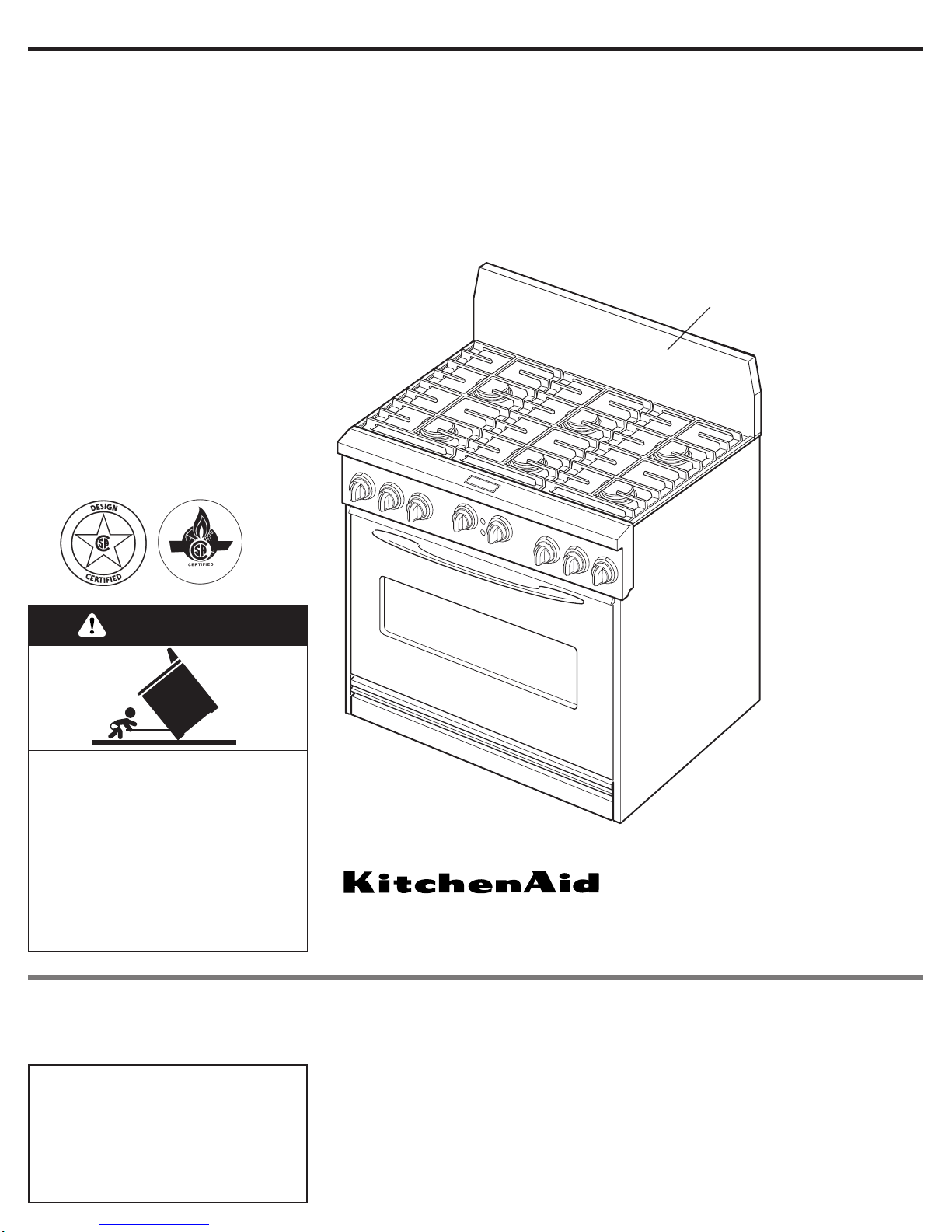
36" (91.4 cm) Commercial Style Dual Fuel Range
with self-cleaning thermal/convection oven
for residential use only
OFF
OFF
OFF
OFF
OFF
OFF
OFF
OFF
backguard
(required for some installations)
For the way it’s made
®
®
Tip Over Hazard
A child or adult can tip the range
and be killed.
Connect anti-tip bracket to wall
behind range.
Reconnect the anti-tip bracket, if
the range is moved.
Failure to follow these instructions
can result in death or serious
burns to children and adults.
WARNING
O
FF
OFF
OFF
O
F
F
O
F
F
OFF
OFF
OFF
Before you start...
It is the customer’s responsibility:
• To contact a qualified electrical installer.
• To assure that electrical installation is
adequate and in conformance with
National Electrical Code, ANSI/NFPA
70 — latest edition**, or CSA Standard,
C22.1 Canadian Electrical Code, Part 1
— latest edition*, and all local codes
and ordinances.
Cabinet opening dimensions shown must
be used. Given dimensions are minimum
clearances.
When installing a range under existing
cabinets and installation does not meet
the minimum cabinet clearances, install a
range hood above the range to avoid burn
hazards.
NOTE: Some cabinet and building
materials are not designed to withstand
the heat produced by the oven for baking
and self-cleaning. Check with your builder
or cabinet supplier to make sure that the
materials used will not discolor,
delaminate or sustain other damage.
All openings in the wall or floor where the
range is to be installed must be sealed.
It is recommended that a range hood be
installed above this range.
NOTE: The range cooktop is
manufactured for use with Natural gas.To
convert to L.P./Propane gas, see the Gas
Conversion instructions provided in
literature package.
Proper gas and electrical supply
connections must be available. See “Gas
supply requirements,” Page 4 and
“Electrical requirements,” Page 5.
IMPORTANT: Observe all governing
codes and ordinances.
Do not obstruct flow of combustion and
ventilation air.
Proper installation is your responsibility.
Have a qualified technician install this
range. Make sure you have everything
necessary for correct installation. It is the
installer's responsibility to comply with the
installation clearances specified on the
gas information label.The gas information
label and model/serial rating plate are
located on the surface below the control
panel.
This installation must conform with all
local codes and ordinances. In the
absence of local codes, installation must
conform with American National
Standard, National Fuel Gas Code ANSI
Z223.1 — latest edition* or CAN/CGA —
B149 — latest edition* installation codes.
WARNING: If the
information in this manual
is not followed exactly, a
fire or explosion may result
causing property damage,
personal injury or death.
— Do not store or use
gasoline or other
flammable vapors and
liquids in the vicinity of
this or any other
appliance.
— WHAT TO DO IF YOU
SMELL GAS
• Do not try to light any
appliance.
• Do not touch any
electrical switch.
• Do not use any phone in
your building.
• Immediately call your
gas supplier from a
neighbor’s phone. Follow
the gas supplier’s
instructions.
• If you cannot reach your
gas supplier, call the fire
department.
— Installation and service
must be performed by a
qualified installer, service
agency or the gas
supplier.
2
Copies of the standards listed may be obtained
from:
* CSA Inter national
8501 East Pleasant Valley Road
Cleveland, Ohio 44131-5575
** National Fire Protection Association
One Batterymarch Park
Quincy, Massachusetts 02269
IMPORTANT: Observe all governing
codes and ordinances.
You can be killed or seriously
injured if you don’t follow
instructions.
DANGER
Your safety and the safety of
others are very important.
We have provided many impor tant
safety messages in this manual and
on your appliance.Always read and
obey all safety messages.
All safety messages will tell you
what the potential hazard is, tell you
how to reduce the chance of injury,
and tell you what can happen if the
instructions are not followed.
You can be killed or seriously
injured if you don’t immediatel
y
follow instructions.
WARNING
This is the safety alert
symbol.
This symbol alerts you to
potential hazards that can kill or hurt
you and others.
All safety messages will follow the
safety alert symbol and either the
word “DANGER” or “WARNING”.
These words mean:
OFF
OFF
OFF
OFF
OFF
OFF
OFF
OFF
3
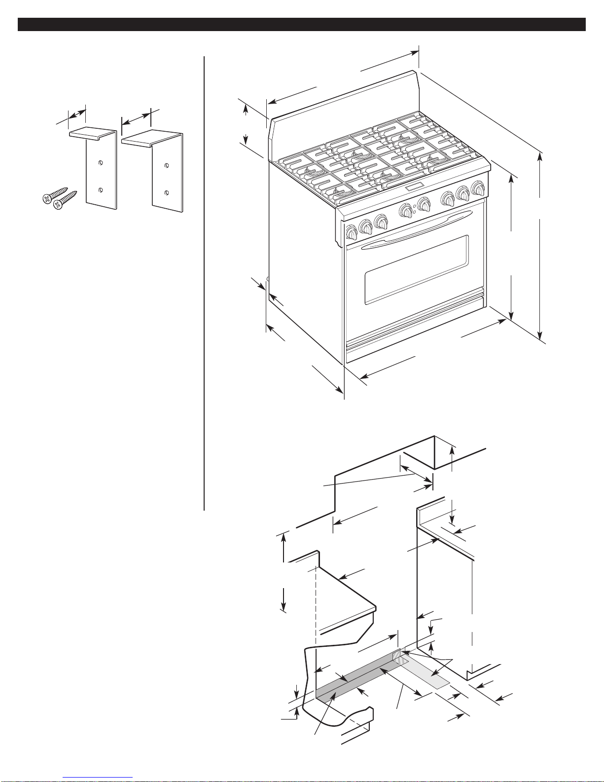
Parts supplied for
installation
Product
dimensions
36" (91.4 cm)
cooktop width
36" (91.4 cm)
width
9-1/4"
(23.5 cm)
anti-tip
brackets
1-3/4"
(4.4 cm)
1"
(2.5 cm)
2 - #10 x 2"
phillips head screws
36" (91.4 cm)
cooktop
height with
feet loosened
3/4 turns
NOTE: regulator
located at center
bottom of range.
36" (91.4 cm) range with
all sealed burners shown
45" (114.3 cm)
overall height
13" (33 cm) max.
upper cabinet depth
1/4" (6.4 mm)
spacer
26-1/2" (67.3 cm)
width with
control panel
• Anti-tip bracket must be securely
attached to a wall stud.Thickness of
finished wall may require using
longer screws to anchor the bracket.
• L.P. conversion kit is included in
literature package.
• Backguard and island trim.The
backguard included with the range
must be installed when a standard
24" (61 cm) deep base cabinet is
used and there is zero clearance
between the back edge of range
and combustible rear wall.
For island installations or other
installations with more than 5"
(12.7 cm) clearance to back wall,
use the optional stainless steel
island trim, included with the range,
to cover the backguard mounting
flanges.
36" (91.4 cm) min.
upper cabinet width
36-1/4" (92.1 cm)
opening width
20"
(50.8 cm)
12"
(30.5 cm)
5-1/2" (14 cm)
8"
(20.3 cm)
18" (45.7 cm)
upper cabinet
to countertop
gas line opening to be
located in this area
junction box to be
located in this area
4" (10.2 cm) min.
clearance from both sides
of range to side wall or
other combustible material
above cooking surface
0" (0 cm) clearance from
both sides and back of
range to adjacent
combustible construction
below cooking surface
*NOTE: 42" (106.7 cm) min. when bottom of wood or
metal cabinet is protected by not less than 1/4" (6.4 mm)
flame retardant millboard covered with not less than
No. 28 MSG sheet steel, 0.015" (0.4 mm) stainless steel,
0.024" (0.6 mm) aluminum or 0.020" (0.5 mm) copper.
48" (121.9 cm) min. clearance between the top of the
cooking platform and the bottom of an unprotected wood
or metal cabinet.
For minimum
clearance to top of
range, see NOTE.*
28"
(71.1 cm)
4"
(10.2 cm)
3" (7.6 cm) maximum
gas line height
3-1/2" (8.9 cm)
maximum junction
box height
Cabinet opening
dimensions
O
FF
O
F
F
O
F
F
O
F
F
O
F
F
O
F
F
O
FF
O
F
F
4
Gas supply
requirements
Observe all governing codes and
ordinances.
IMPORTANT: Range cooktop must be
connected to a regulated gas supply.
A.This installation must conform
with local codes and ordinances. In the
absence of local codes, installations must
conform with American National
Standard, National Fuel Gas Code
ANSI Z223.1 — latest edition* or
CAN/CGA-B149 — latest edition*
installation codes.
B.Input ratings shown on the
model/serial rating plate are for elevations
up to 2,000 feet (610 m). For elevations
above 2,000 feet (610 m), ratings are
reduced at a rate of 4% for each 1,000
feet (305 m) above sea level. (Not
applicable for Canada.)
Copies of the standards listed may be
obtained from:
* CSA Inter national
8501 East Pleasant Valley Road
Cleveland, Ohio 44131-5575
D.
Provide a gas supply line of 3/4"
(1.9 cm) rigid pipe to the range location. A
smaller size pipe on long runs may result
in insufficient gas supply. Pipe-joint
compounds, appropriate for use with L.P.
gas, must be used.With L.P. gas, piping or
tubing size can be 1/2" (1.3 cm) minimum.
L.P. gas suppliers usually deter mine the
size and materials used on the system.
L.P. Gas:
No attempt shall be made to convert the
cooktop from the gas specified on the
model/serial rating plate for use with a
different gas without consulting the
serving gas supplier. Conversion must be
done by a qualified service technician.To
convert to L.P. gas, use L.P. gas
conversion kit part no.8301439.The parts
for this kit are in the literature package
supplied with range.
E.If local codes permit, a new AGA
or CSA design-certified, 4-5 foot (122-
152.4 cm) long, 5/8" (1.6 cm) I.D., flexible
metal appliance connector is
recommended for connecting this range
to the gas supply line. Do not kink or
damage the flexible tubing when moving
the range. A 1/2
"
(1.3 cm) male pipe
thread is needed for connection to
pressure regulator female pipe threads.
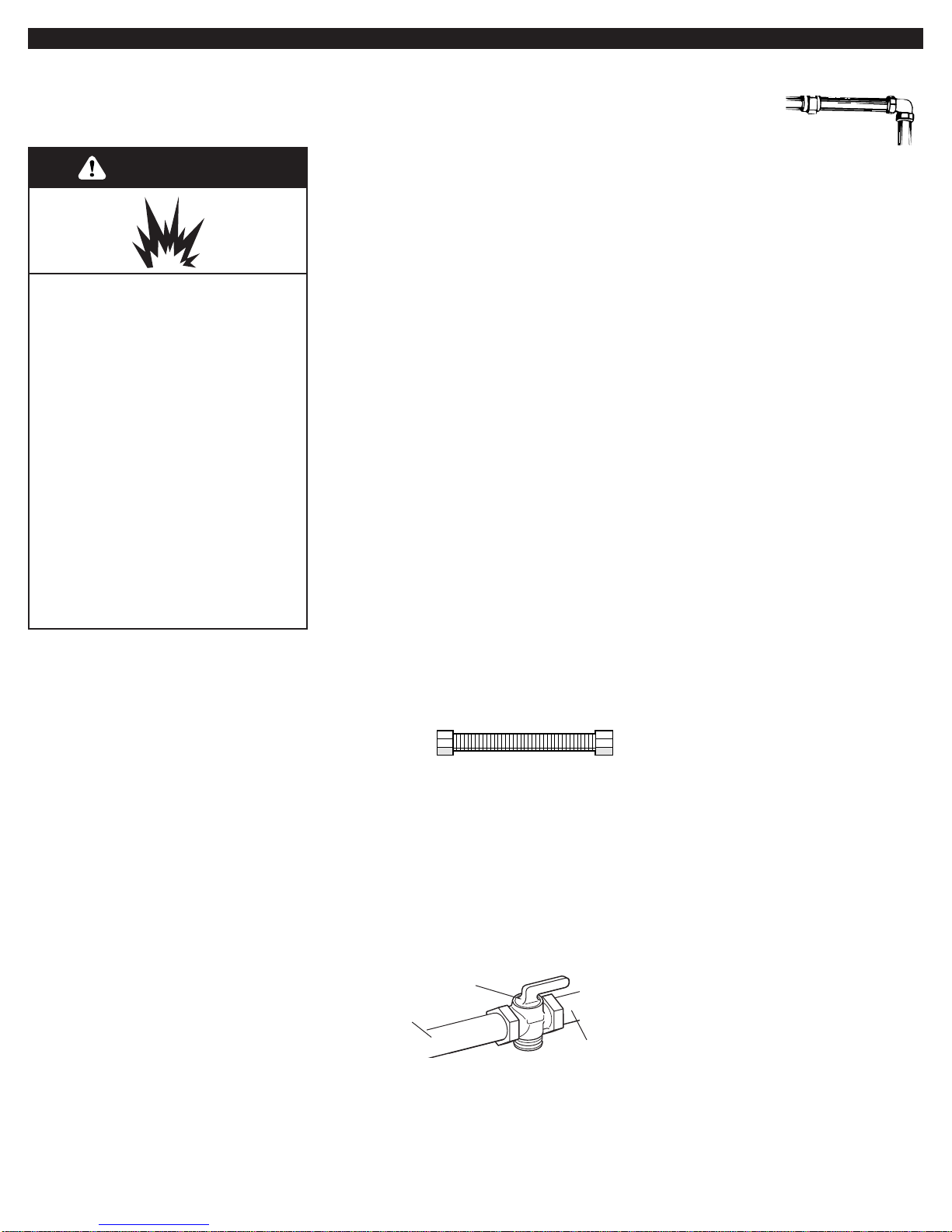
F.The supply line shall be equipped
with an approved shutoff valve.This valve
should be located in the same room, but
external to the range, and should be in a
location that allows ease of opening and
closing. Do not block access to the
shutoff valve.
gas supply
line
shutoff valve
“open” position
G.If rigid pipe
is used as a gas
supply line, a combination of pipe
fittings must be used to obtain an in-line
connection to the range. All strains must
be removed from the supply and fuel lines
so range will be level and in line.
to range
H.The regulator must be checked at a
minimum 1-inch (25.4 mm) water column
above the set pressure.The inlet pressure to
the regulator should be as follows for
operation and checking the regulator setting:
NATURAL GAS:
Manifold pressure –
5 inches (12.7 cm) W.C.
Maximum pressure –
14 inches (35.6 cm) W.C.
L.P. GAS:
Manifold pressure –
10 inches (25.4 cm) W.C.
Maximum pressure –
14 inches (35.6 cm) W.C.
I.Line pressure testing:
Testing above 1/2 psi (3.5 kPa) (gauge):
The range and its individual shutoff valve
must be disconnected from the gas
supply piping system during any pressure
testing of that system at test pressures
greater than 1/2 psig (3.5 kPa).
Testing at 1/2 psi (3.5 kPa) (gauge)
or lower: The range must be isolated from
the gas supply piping system by closing
its individual manual shutoff valve during
any pressure testing of the gas supply
piping system at test pressures equal to
or less than 1/2 psig (3.5 kPa).
C.
The range is equipped for use with
NATURAL gas. It is design-certified by
International Approval Services (I.A.S.) for
NATURAL and L.P. gases with appropriate
conversion.The model/ser ial rating plate,
located on the surface below the control
panel, has information on the type of gas
that can be used. If this information does
not agree with the type of gas available,
check with the local gas supplier.
WARNING
Explosion Hazard
Use a new AGA or CSA approved
gas supply line.
Install a shutoff valve.
Securely tighten all gas
connections.
If connected to LP, have a
qualified person make sure gas
pressure does not exceed 14"
(35.6 cm) water column.
Examples of a qualified person
include:
Licensed heating personnel,
Authorized gas company
personnel, and
Authorized service personnel.
Failure to do so can result in
death, explosion, or fire.
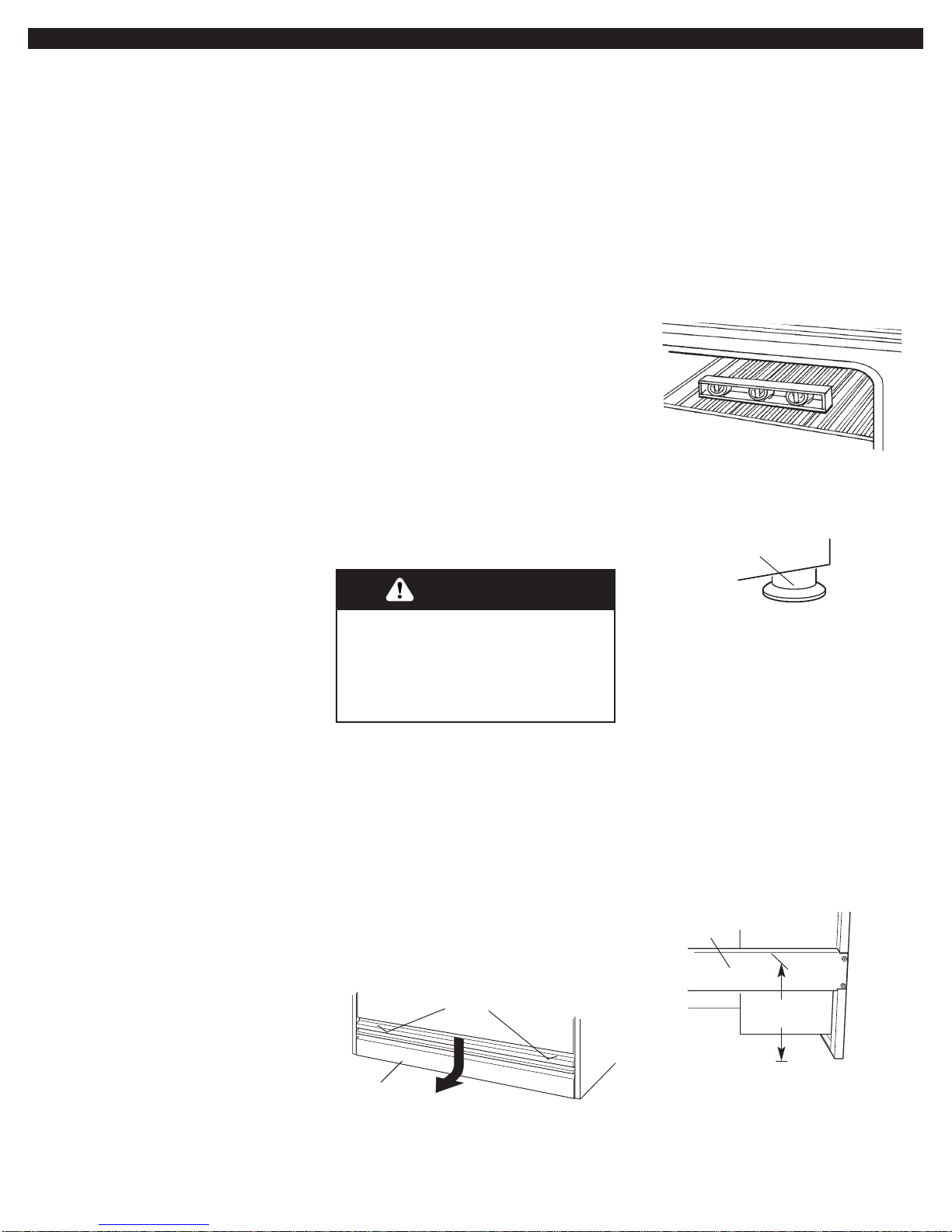
4.Carefully move range
close to the cabinet opening. Place the
rack in oven.Place level on rack, first side
to side; then front to back.
If the range is not level, adjust the feet up
or down.Tur n leveling leg sleeves to level
range and to raise or lower range to the
desired countertop height.
5
remove
screws
bottom
vent
leveling leg
sleeves
Electrical
requirements
F. Connection at connection block must
be copper wire only.
If the house has aluminum wiring, follow
the procedure below:
a) Connect the aluminum wiring to the
copper wiring using special connectors
designed and Underwriters
Laboratories-listed for joining copper to
aluminum. Follow the electrical
connector manufacturer’s recommended
procedure.
b) Aluminum/copper connection must
conform with local codes and industryaccepted wiring practices.
Copies of the standards listed may be obtained
from:
* National Fire Protection Association
One Batterymarch Park
Quincy, Massachusetts 02269
**CSA International
8501 East Pleasant Valley Road
Cleveland, Ohio 44131-5575
If codes permit and a separate ground
wire is used, it is recommended that a
qualified electrician determine that the
ground path and wire gauge are in
accordance with local codes.
Do not ground to a gas pipe.
Check with a qualified electrician if you
are not sure the range is properly
grounded.
Do not have a fuse in the neutral or
ground circuit.
This range must be connected to a
grounded metal, permanent wiring
system.
A.A four-wire or three-wire, single
phase, 240-volt, 60-Hz, AC-only electrical
supply is required on a separate, 30ampere circuit, fused on both sides of the
line. A time-delay fuse or circuit breaker is
recommended.The fuse size must not
exceed the circuit rating of the range
specified on the model/serial rating plate
located on the horizontal surface below
the control panel.
B.Wire sizes and connections must
conform to the requirements of the
National Electrical Code ANSI/NFPA 70 –
latest edition*, or CSA Standards C22.194, Canadian Electrical Code, Part 1 and
C22.2 No.0-M91 - latest edition** and all
local codes and ordinances.
C.The range should be connected
directly to the fused disconnect or circuit
breaker box through flexible, armored or
non-metallic sheathed, copper cable.The
flexible, armored cable extending from the
fuse box or circuit breaker box should be
connected directly to the junction box.
D.Locate the junction box to allow
as much slack as possible between the
junction box and the range so that the
range can be moved if servicing is ever
necessary.Do not cut the conduit.
E.A U.L.- or CSA-listed conduit
connector must be provided at each end
of the power supply cable (at the cooktop
and at the junction box).
Installation
Excessive Weight Hazard
Use two or more people to move
and install range.
Failure to do so can result in back
or other injury.
WARNING
1.Put on safety glasses and gloves.
Remove shipping materials, tape and
protective film from range.Keep shipping
pallet under range. Unpack the burner
grates, burner caps, simmer plate, grille
grate, drip tray, spill guard, wave tray,
wave plate, tile bezels, regulator,
backguard and island trim. Items are
either packaged in the range or on the
range. Parts shipped with range depend
on model ordered.
2.Remove the bottom vent by
removing the 2 screws on each side of
the top of the bottom vent, Slide the vent
3.Lay a piece of cardboard from side
packing on the floor behind range.Using
2 people, firmly grasp each side of range.
Lift range up about 3 inches (8 cm) and
move it back until the range is off
shipping pallet. Set range on cardboard to
avoid damaging floor.
5.Choose the correct bracket for your
installation.
• If the wall behind the range has no
baseboard or a baseboard up to 3/8
"
(9.5 mm) thick, use the shorter 1
"
(2.5 cm) anti-tip bracket.
• If the wall behind the range has a
baseboard thicker than 3/8
"
(9.5 mm),
use the longer 1-3/4
"
(4.4 cm) anti-tip
bracket.
Locate a stud in wall behind range.
Measure distance from top of rear brace
to floor.Add 5/16
"
(7.9 mm) to
measurement to allow anti-tip bracket to
slide over rear brace.Use this final
measurement and mark a horizontal line
on wall where stud is located.
write down
this distance
rear
brace
down and pull toward you.Carefully lay
this part to the side to avoid scratching
the stainless steel.
6
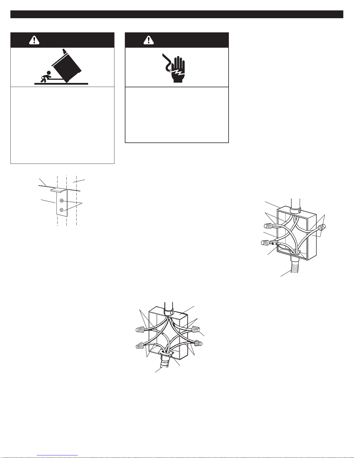
6.Position top of anti-tip bracket at
line marked in step 5 and mark holes.
Drill two 1/8" (3 mm) holes. Use screws
provided to fasten anti-tip bracket to wall.
NOTE: Anti-tip bracket must be mounted
securely to stud in wall behind the range.
Depending on thickness of the wall
covering, longer screws may be required.
7.Make electrical connection.
If your house has aluminum wiring, see
“Electrical requirements” page 5.
wall stud
line
mounting
screws
anti-tip
bracket
This range must be connected to a
grounded, metallic permanent wiring
system or a ground connector should be
connected to the ground terminal or wire
lead on the range.
This range is manufactured with a frameconnected, green or bare ground wire
factory-cr imped to the neutral (white)
wire. Connect the range cable to the
junction box through the U.L.- or CSAlisted conduit connector.Complete
electrical connection according to local
codes and ordinances.
7A.Where local codes Do Not
permit connecting the frame-ground
conductor to the neutral (white) junction
box wire (also used for Canadian
installations):
1. Disconnect power supply.
2. Connect the flexible, armored cable
from the range to the junction box
using a U.L.- or CSA-listed conduit
connector.Tighten screws on conduit
connector.
junction box
4-wire cable from power supply
twist-on
connector
black wires
U.L.- or CSA- listed
conduit connector
4-wire cable from range
bare or green
wires
white wires
red wires
Figure 1
Ungrounded neutral
7B.Where local codes per mit
connecting the frame-ground conductor to
the neutral (white) junction box wire (not
used for Canadian installations):
Figure 2
Grounded neutral
junction
box
red
wires
white
wire
white and bare grounding
oven cable wires —
factory crimped
3-wire cable from
power supply
black
wires
4-wire cable from range
U.L.- or CSA- listed
conduit connector
1. Disconnect power supply.
2. Connect the flexible, armored cable
from the range to the junction box
using a U.L.- or CSA-listed conduit
connector.Tighten screws on conduit
connector.
3. Connect the two black wires together;
the two red wires together; and the
factory-cr imped bare and white
cooktop cable wires to the white
(neutral) wire in the junction box using
twist-on connectors. (See Figure 2.)
3. Connect the two black wires
together; and the two red wires
together using twist-on connectors.
(See Figure 1.)
4. Separate the factory-crimped bare
and white range cable wires.
5. Connect the two white wires together
using twist-on connector.
6. Connect the bare ground wire from
the range cable to the grounded wire
in the junction box or other grounded
connector using twist-on connector.
(See Figure 1.) Do not connect bare
ground wire to neutral (white) wire in
junction box.
Electrical Shock Hazard
Disconnect power before servicing.
Use 8 gauge copper wire.
Electrically ground range.
Failure to follow these instructions
can result in death, fire, or
electrical shock.
WARNING
Tip Over Hazard
A child or adult can tip the range
and be killed.
Connect anti-tip bracket to wall
behind range.
Reconnect the anti-tip bracket, if
the range is moved.
Failure to follow these instructions
can result in death or serious
burns to children and adults.
WARNING
7
8.Remove cardboard or hardboard
from under range.
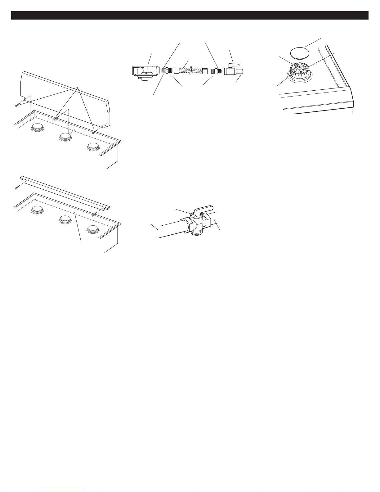
9.Attach the backguard or island trim
as required for your installation.
Attachment screws are in the literature
package.
10.Slide range completely back so
anti-tip bracket is over rear brace of
range.
11. Make gas connection. Assemble
flexible connector from gas supply pipe to
pressure regulator located in the middle
front of the range. Apply pipe-joint
compound made for use with L.P. gas to
the smaller thread ends of the flexible
connector adapters. Attach one adapter
to the pressure regulator elbow and the
other adapter to the gas shutoff valve.
Tighten both adapters.
13. Leak testing of the appliance
shall be conducted according to the
following instructions:
Use a brush and liquid detergent to test
all gas connections for leaks.Bubbles
around connections will indicate a leak. If
a leak appears, shut off gas valve
controls and adjust connections.Then
check connections again. Clean all
detergent solution from range.
14. Put a burner cap on each
burner base. Place burner grates over
burner bases and caps.
If your model has only surface burners
(no grille or griddle), go to “Check the
operation of the surface burners, grille
and griddle” on Page 9.
If your model was shipped with a grille or
griddle, go to “Installing the grille or
griddle” on Page 8 to complete the
installation.
15.Turn on power supply. “PF”
should appear in the clock display. (Refer
to your Use and Care Guide for
instructions on using the electronic
control.)
12. Open manual shutoff valve in
gas supply line.Wait a few minutes for
gas to move through the line.
attaching the
backguard
attaching the island
trim
center hole
not used
3 front screws
(4 rear screws required
but not shown)
use pipe-joint
compound
flexible
connector
1/2" flare union
adapter
manual gas
shutoff valve
1/2" to 3/4" gas
pipe
a 1/2" male pipe thread is needed for connection
to pressure regulator female pipe threads
regulator
gas supply
line
shutoff valve
“open” position
to range
burner cap
burner
base
ignitor
electrode
gas tube
opening
8
Installing the grille
or griddle.
Grille installation: Go to Step 16.
Griddle installation: The griddle is factory
installed.To complete the installation, go
to Step 17.
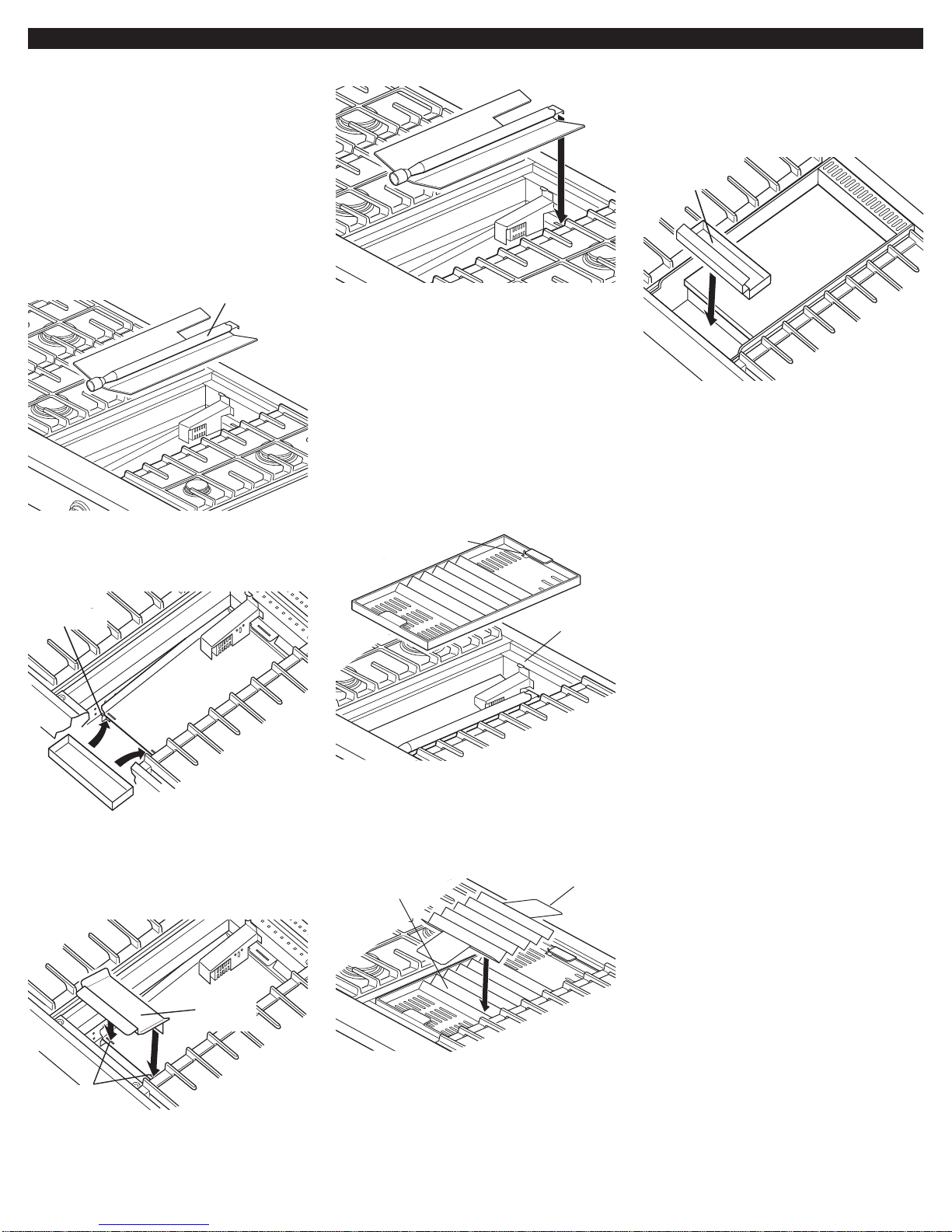
16.Installing the grille:
17.Completing the griddle
installation:
A. Lift the log burner up out of the bay
and set aside.
B. Place drip tray on bottom of grille
bay and slide the tray forward so that it is
located side-to-side and against the
locating feet of the rear spill guard.
C. Insert the front spill guard feet into
the slots in the rear spill guard as shown.
The rear flange will rest on the burner box.
D. Reinstall the log burner.Make sure
burner’s rear flange is seated in slot.
G. Install the wave tray into the grille
bay. The tab in the left rear cor ner of the
bay must fit through the slot in the left
rear corner of the wave tray.
H. Place the wave plate on the wave
tray as shown.The wave plate must be
centered on the wave tray.
E. Plug power supply cord into
grounded outlet.
C. Plug power supply cord into
grounded outlet.
I. Install the grille grate.
A. Place drip tray in the well at the
front of the griddle. Slide tray forward until
it stops.
B. Refer to the Use and Care Guide
that came with your Cooktop for
instructions on cleaning and seasoning
the griddle before using.
D. Check the surface burner and
griddle flames. Go to “Check the
operation of the surface burners, grille
and griddle” on Page 9.
F. Check the surface burner and grille
flames. Before completing the grille
installation, go to “Check the operation of
the surface burners, grille and griddle” on
Page 9.
locating feet
rear spill
guard
drip
tray
log burner
griddle drip
tray
griddle
front spill
guard
insert feet
into slots
locating
tab
wave
plate
wave
tray
slot for
locating tab
 Loading...