

KitchenAid Architect Series KBMS1454R Installation Instructions Manual
BUILT-IN MICROWAVE OVEN
INSTALLATION INSTRUCTIONS
24" (61.0 cm), 27" (68.6 cm), 30" (76.2 cm)
This product is suitable for use above electric or gas built-in ovens, and below non-vented electric or gas
cooktops. This product is not suitable for use below downdraft cooktops.
These installation instructions cover different models. The appearance of your particular model may differ
slightly from the illustrations in these Installation Instructions.
Table of Contents
MICROWAVE OVEN SAFETY...........................................................1
INSTALLATION REQUIREMENTS ...................................................2
Tools and Parts...............................................................................2
Location Requirements................................................................... 2
Minimum Dimensions ..................................................................... 3
Product Dimensions ....................................................................... 4
Electrical Requirements.................................................................. 5
INSTALLATION INSTRUCTIONS .....................................................6
Install the Microwave Oven
24" (61.0 cm) Installation Only....................................................... 6
Install the Microwave Oven
27" (68.6 cm) or 30" (76.2 cm) Installation Only ........................... 7
Complete Installation ......................................................................8
ASSISTANCE ..................................................................................... 8
MICROWAVE OVEN SAFETY
Your safety and the safety of others are very important.
We have provided many important safety messages in this manual and on your appliance. Always read and obey all safety
messages.
This is the safety alert symbol.
This symbol alerts you to potential hazards that can kill or hurt you and others.
All safety messages will follow the safety alert symbol and either the word “DANGER” or “WARNING.”
These words mean:
You can be killed or seriously injured if you don't immediately
DANGER
WARNING
All safety messages will tell you what the potential hazard is, tell you how to reduce the chance of injury, and tell you what can
happen if the instructions are not followed.
follow instructions.
can be killed or seriously injured if you don't
You
instructions.
follow
IMPORTANT: Read Installation Instructions thoroughly before beginning installation. Save Installation Instructions for local electrical
inspector’s use.
8205303/4619-694-50851
INSTALLATION REQUIREMENTS
Tool s an d P art s
Tools Needed
Gather the required tools and parts before starting installation.
Read and follow the instructions provided with any tools
listed here.
■ Measuring tape
■ Pencil
■ Torx T-10 screwdriver
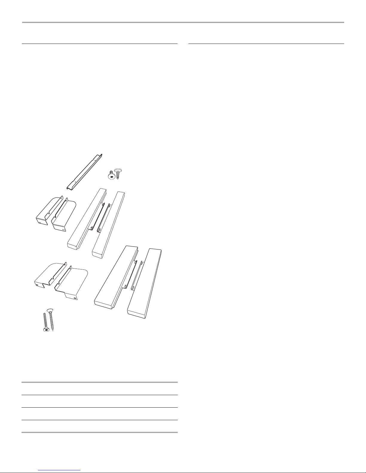
Parts Supplied
All of the following parts are provided, but not all parts will be
used. The cutout opening size will determine which parts you will
use. See chart below parts list to see which parts are used for
each installation.
A
C
■ Electric drill
■ 5/64" (2 mm) drill bit
B
D
Location Requirements
The microwave oven may be located in a cabinet, and/or above a
built-in oven, or below the counter and/or below a non-vented
cooktop. Check the opening where the microwave oven will be
installed. The location must provide:
■ Wood cabinetry.
■ Cutout opening that is plumb and square. For proper
installation, the bottom corners must be cut at right angles.
See “Minimum Cutout Dimensions” section.
■ Cutout floor that is solid, level and flush with bottom of
cabinet cutout.
■ Support for weight of at least 150 lbs (68 kg), which includes
microwave oven and items placed inside.
■ Grounded electrical outlet. See “Electrical Requirements”
section.
■ Minimum installation clearances for installation location. See
“Minimum Dimensions” section.
We recommend:
■ Complete enclosure around the recessed portion of the
microwave oven.
F
E
G
A. Z-brackets (2)
B. 1/2" T-10 screws (6)
C. Narrow side brackets, marked LEFT 27" and RIGHT 27" (2)
D. Narrow side trim panels (2)
E. Wide side brackets, marked LEFT 30" and RIGHT 30" (2)
F. Wide side trim panels (2)
G. 1" T-10 screws (4)
INSTALLATION PARTS USED
24" (61.0 cm) installation G
27" (68.6 cm) installation A, B, C, D, G
30" (76.2 cm) installation A, B, E, F, G
2
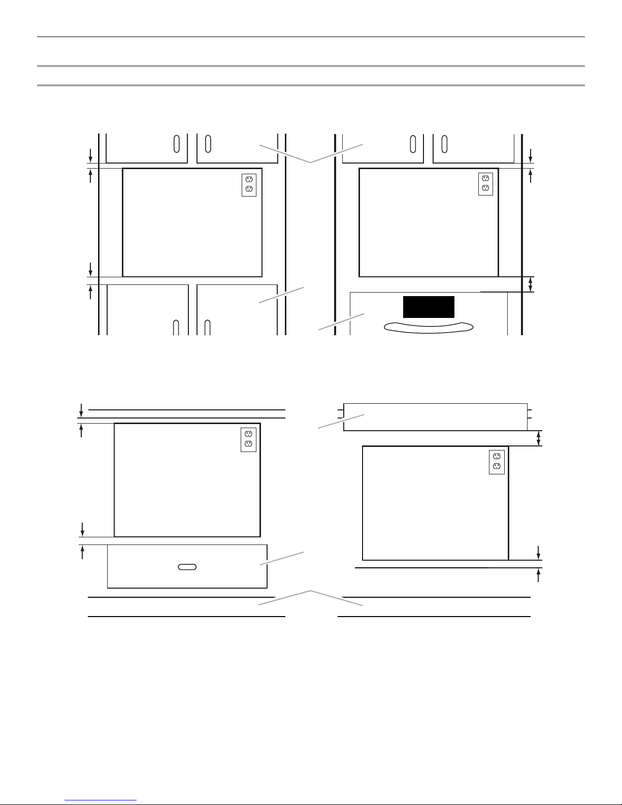
Minimum Dimensions
Minimum Installation Clearances
For proper installation, the following minimum clearances must exist above and below the cutout opening.
Above Cabinet/Storage Drawer Installation Above Oven/Warming Drawer Installation
1"
(2.5 cm)
1
¹⁄₂
(3.8 cm)
1"
(2.5 cm)
A
"
B
1"
(2.5 cm)
3"
(7.6 cm)
C
Below Counter Installation Below Built-in Cooktop Installation
D
3"
(7.6 cm)
See note
below.
1¹⁄₂"
(3.8 cm)
A. Upper cabinet
B. Lower cabinet or storage drawer
C. Lower oven or warming drawer
E
(3.8 cm)
F
D. Built-in cooktop (non-vented)
E. Storage drawer
F. Toe kick
NOTE: The bottom of the cooktop may be sunk into the counter
and lower cabinet. The minimum 3" (7.6 cm) clearance must exist
below the lowest point of the cooktop, and there must be no
interference between any part of the cooktop (including any gas
fittings) and the microwave oven.
¹⁄₂"
1
3
 Loading...