

KitchenAid 883298, 6899552 User Manual
Quick Reference
Table of Contents:
Pages
1 Product dimensions
0
1 Cabinet dimensions
cl
Before you start
q
2 Venting requirements
0
3 Electrical requirements
cl
13 m @l Installation steps
5 Use and Care Information
cl
m Warranty; Accessories
piiziiq
The KitchenAid Consumer Assistance Center:
The KitchenAid Consumer Assistance Center is open 24 hours a day,
7 days a week. Call l- (800) 422-1230. (The call is free within the
continental United States.)
Call the KitchenAid Consumer Assistance Center when you:
q
Have questions about range hood installation or operation.
q
Need to obtain the name and number of a KitchenAid-authorized
service company.
Wiring diagram
When you call, you will need:
q
The range hood model number.
q
The range hood serial number.
Both numbers are listed on the serial/rating plate, located inside the
range hood on the rear wall.
5-v

f t
1” min. - IO-3/8” max.
upper chimney height
23-518” lower
chimney height
24-518” min. 34-314” max.
overall
chimney
height
I
t
10-l/4”
canopy
Important: Observe all governing codes
and ordinances.
Proper installation is your responsibility:
l
Have a qualified technician install this range hood.
l
Comply with installation clearances specified on the
serial/rating plate.
Serial/rating plate is located inside the range hood on
the rear wall.
Range hood location should be away from strong draft
areas, such as windows, doors and strong heating
vents.
Cabinet opening dimensions that are shown must be
used. Given dimensions provide minimum clearance.
Consult your cooktop/range manufacturer installation
instructions before making any cutouts.
Grounded electrical outlet is required. See “Electrical
requirements.”
Ductwork must terminate outdoors,
All openings in ceiling and wall where range hood will
be installed must be sealed.
Electrical Shock Hazard
It is the customer’s responsibility:
*To contact a qualified electrical installer.
*To assure that the electrical installation is
adequate and in conformance with National
Electrical Code, ANSVNFPA 70 - latest edition’,
and all local codes and ordinances.
Failure to do so could result in fire, electrical shock
or other personal injury.
support IP
structure
Electrical Shock Hazard
*Take special care cutting holes into ceiling or wall.
Electrical wires may be concealed behind the
ceiling or wall cover and contact with them could
result in electrical shock.
l
Locate any electrical circuits that could be
affected by the installation of this product and
disconnect power circuit.
Failure to do so could result in fire, electrical shock
- upper chimney
or other personal injury.
Personal Injury Hazard
Reaching over a heated cooking surface should be
avoided. To reduce the hazard of being burned, the
range hood should extend a minimum of 5 inches
out from the bottom of the cabinet.
Reaching over a heated cooking surface could
- lower chimney
result in a serious burn.
Tools needed:
/
- canopy
- l-1/4” drill bit
I
24” min. bottom
of canopy to
cooking surface
-f
36” base
cabinet
height
cooking surface
\
8’ min. 9’ max.
ceiling
to floor
caulking gun and
saw
duct tape
allen
wrench
Parts needed:
2 U.L.-listed, l/2” conduit
connectors
power supply cable
flat
wall or roof cap
metal ductwork
Page 1
Mobile home installation
The installation of range hood must conform to the
Manufactured Home Construction and Safety Standards,
Title 24 CFR, Part 3280 (formerly the Federal Standard
for Mobile Home Construction and Safety, Title 24, HUD
Part 280); or when such standard is not applicable, the
Standard for Manufactured Home Installation 1982
(Manufactured Home Sites, Communities and Setups),
ANSI Z225.1/NFPA 501A, or with local codes.
Four-wire power supply must be used and the appliance
wiring must be revised. See “Electrical requirements.”
Copies of the standards listed may be obtained from:
l
National Fire Protection Association
Batterymarch Park
Quincy, Massachusetts 02269
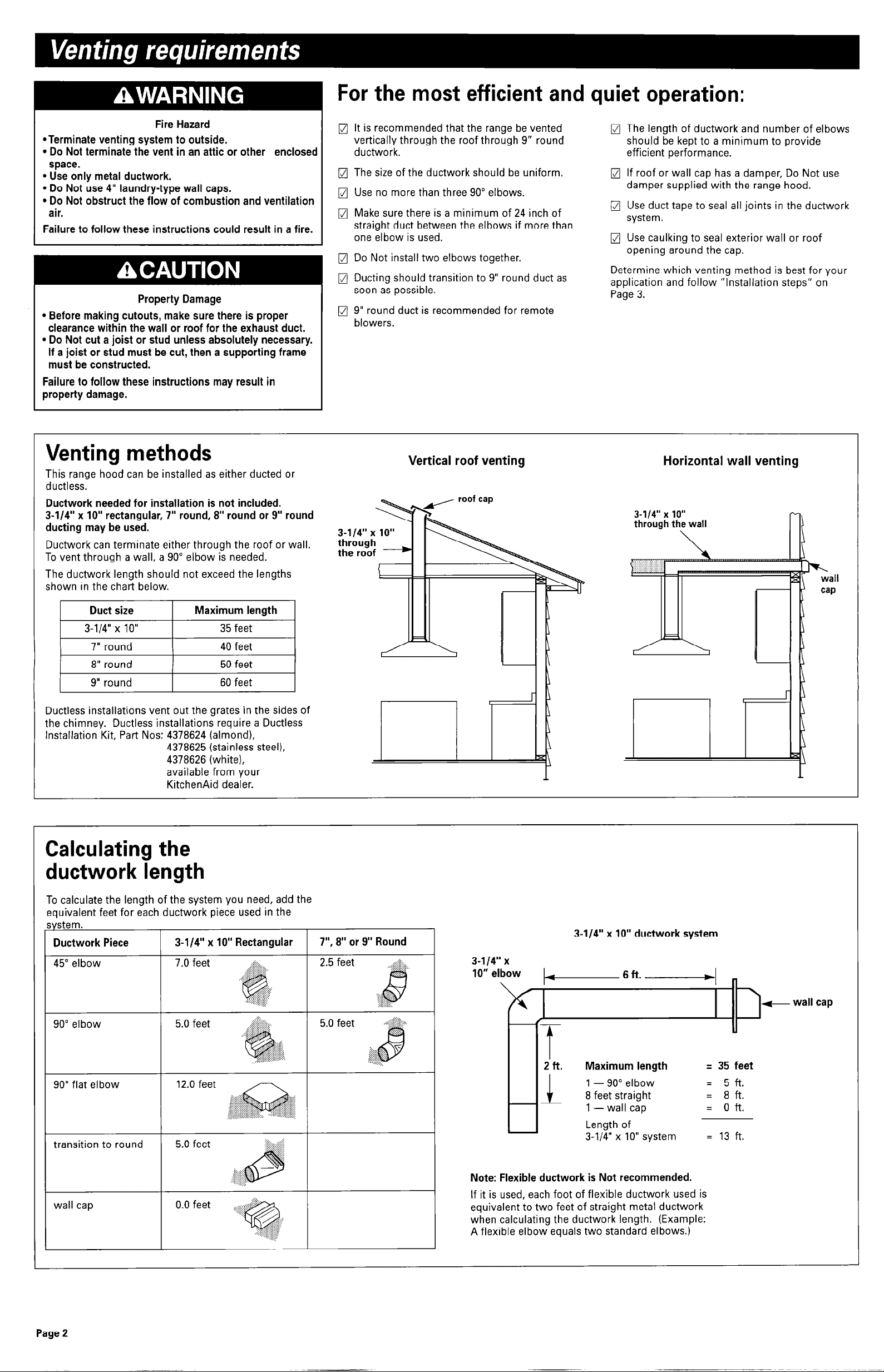
For the most efficient and quiet operation:
Fire Hazard
*Terminate venting system to outside.
l Do Not terminate the vent in an attic or other
space.
l Use only metal ductwork.
l Do Not use 4” laundry-type wall caps.
l Do Not obstruct the flow of combustion and ventilation
air.
Failure to follow these instructions could result in a fire.
Property Damage
l Before making cutouts, make sure there is proper
clearance within the wall or roof for the exhaust duct.
l Do Not cut a joist or stud unless absolutely necessary.
If a joist or stud must be cut, then a supporting frame
must be constructed.
Failure to follow these instructions may result in
property damage.
enclosed
q
It is recommended that the range be vented
vertically through the roof through 9” round
ductwork.
q
The size of the ductwork should be uniform.
q
Use no more than three 90” elbows.
q
Make sure there is a minimum of 24 inch of
straight duct between the elbows if more than
one elbow is used.
m Do Not install two elbows together.
q
Ducting should transition to 9” round duct as
soon as possible.
jJ 9” round duct is recommended for remote
blowers.
q
The length of ductwork and number of elbows
should be kept to a minimum to provide
efficient performance.
q
If roof or wall cap has a damper, Do Not use
damper supplied with the range hood.
q
Use duct tape to seal all joints in the ductwork
system.
q
Use caulking to seal exterior wall or roof
opening around the cap.
Determine which venting method is best for your
application and follow “Installation steps” on
Page 3.
Venting methods
This range hood can be installed as either ducted or
ductless.
Ductwork needed for installation is not included.
3-l/4” x IO” rectangular, 7” round, 8” round or 9” round
ducting may be used.
Ductwork can terminate either through the roof or wall.
To vent through a wall, a 90” elbow is needed.
The ductwork length should not exceed the lengths
shown in the chart below.
Duct size
3-l/4” x 10”
7” round 40 feet
8” round 50 feet
9” round
Ductless installations vent out the grates in the sides of
the chimney. Ductless installations require a Ductless
Installation Kit, Part Nos: 4378624 (almond),
Maximum length
35 feet
60 feet
4378625 (stainless steel),
4378626 (white),
available from your
KitchenAid dealer.
Vertical roof venting Horizontal wall venting
Calculating the
ductwork length
To calculate the length of the system you need, add the
equivalent feet for each ductwork piece used in the
system.
Ductwork Piece
45” elbow
90” elbow
90” flat elbow
transition to round
wall cap
3-l/4” x IO” Rectangular
7.0 feet .s:i:..
5.0 feet .~~~ii:,
12.0 feet
5.0 feet
0.0 feet
.,::,i;ijiig
,..:::,:p’ ., .:.;::
..:&~
,.:,:.:.:.:.: :.:
:~:
,f:~fiigl-::‘::i:~
..+y:,:::.
...>F.
::.:: ,,.:.:3::;:sy
:::1 :.:.;:::::.:::.;:.:
@::.;::
:,:~:siigijipijii:g:
,.l):.:........~.~~
:.:.:.:.: >: ,:::.,,
.::‘:::::::‘:::.. ..:.::>>- . . . . . . . ..-....:i:~B:
. . . . .,.,.....,.,...,....., ..)
:~i.~:i:i:‘:~:i:8:i:8::::~.,
~~~~
i; jz$j:. “:
:i:g:o
. . . . . i::.::;
:;“‘::.,:;:::;:;:;:;:;:;
.: ..::;:;
-
7”, 8” or 9” Round
2.5 feet
5.0 feet .:::liis:..
. . . &:..
. . . . . . . . . . . .
.,... .,., 1
.+>>,.
.A..
‘&,.?$>.
@
.:;*;:{:A :.
,.,.. . . . .
..:.:.:.:.:.:.:.:.: :.:..
3-l /4” x IO” ductwork system
3-l 14” x
10” elbow
Maximum length
1 - 90” elbow
3-l/4” x IO” system
Note: Flexible ductwork is Not recommended.
If it is used, each foot of flexible ductwork used is
equivalent to two feet of straight metal ductwork
when calculating the ductwork length. (Example:
A flexible elbow equals two standard elbows.)
w wall cap
q 35 feet
= 5ft.
= 8ft.
= oft.
= 13 ft.
Page 2
 Loading...