

Installation Instructions
for your new undercounter
COMPACTOR
BEFORE YOU USE YOUR COMPACTOR. . .
Be sure your compactor is properly installed in an appropriate level area and a place suitable for the size, function
and protection of the compactor.
ELECTRICAL REQUIREMENTS
Observe All Governing Codes and Ordinances
A 120-Volt, 60 Hz, AC only, 15Ampere fused electrical supply is required. (Time delay fuse or circuit breaker is
recommended.) It is recommended that a separate circuit serving only this appliance be provided. DO NOT use
an extension cord.
RECOMMENDED GROUNDING METHOD
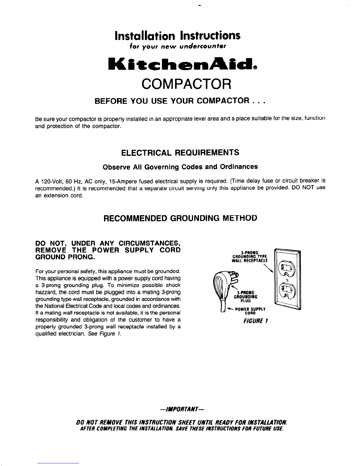
DO NOT, UNDER ANY CIRCUMSTANCES,
REMOVE THE POWER SUPPLY CORD
GROUND PRONG.
&PRONG
GAOUNOING TYPE
WALL RECEPTACLE
For your personal safety, this appliance must be grounded.
This appliance is equipped with a power supply cord having
a 3-prong grounding plug. To minimize possible shock
hazard, the cord must be plugged into a mating 3-prong
grounding type wall receptacle, grounded in accordance with
the National Electrical Code and local codes and ordinances.
If a mating wall receptacle is not available, it is the personal
responsibility and obligation of the customer to have a
properly grounded 3-prong wall receptacle installed by a
qualified electrician. See Figure 7.
FIGURE 1
--/MPORTANT-
00 NOT REMOVE THIS INSTRUCTION SHEET UNTll READY FOR INSTAUATION.
AFTER COMPLETING THE INSTAllA TIOM SAVE THESE INSTRUCTIONS FOR FUTURE USE.
INSTALLATION INSTRUCTIONS
BEFORE YOU BEGIN, READ THE FOLLOWING INSTRUCTIONS COMPLETELY AND
CAREFULLY. THEY WILL SIMPLIFY THE INSTALLATION.
1.
After removing the shipping carton, be sure to remove
all protective packaging materials such as tape and
shipping pads. Waxy residue from protective shipping
material may be removed from compactor with a mild
solution of liquid household cleaner and water.
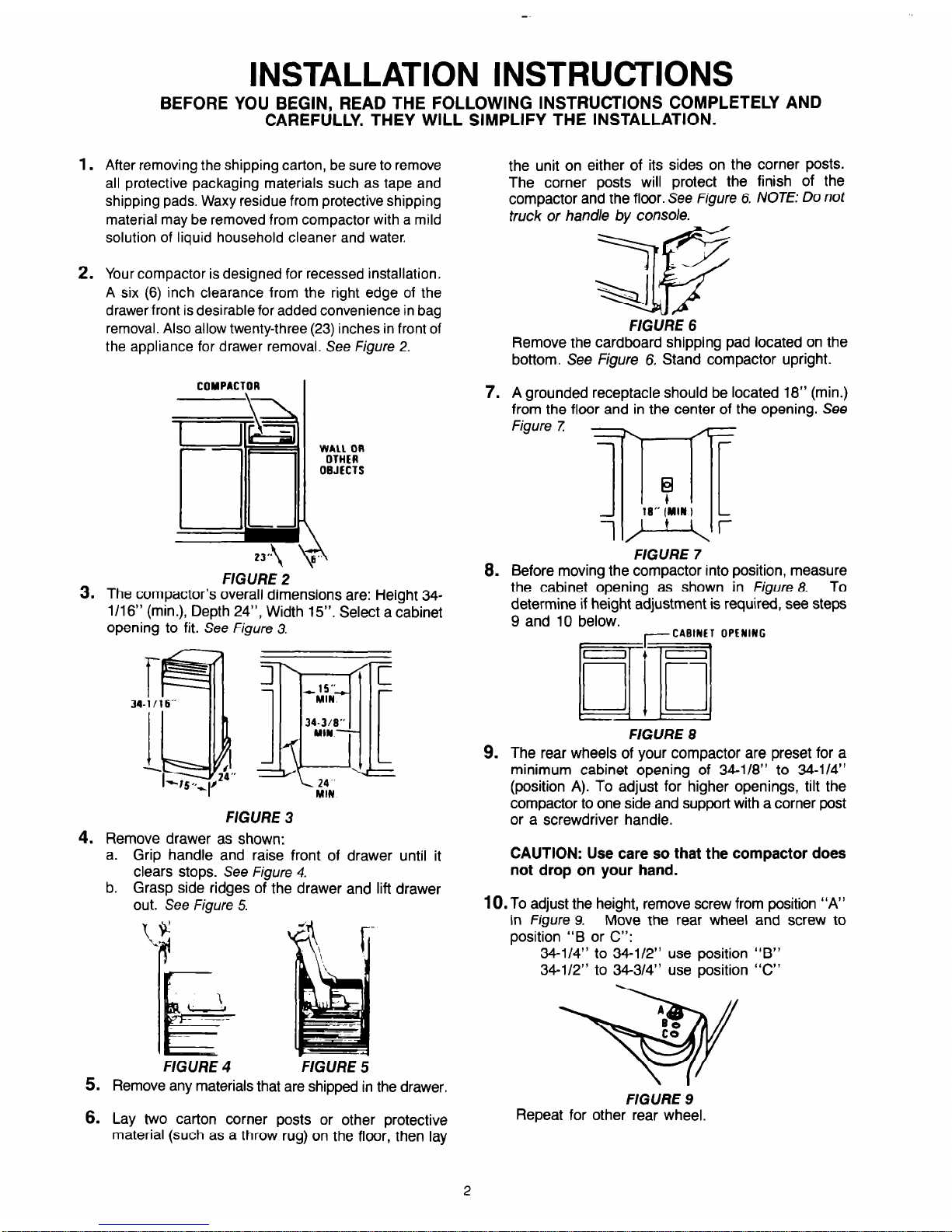
2. Your compactor is designed for recessed installation.
A six (6) inch clearance from the right edge of the
drawer front is desirable for added convenience in bag
removal. Also allow twenty-three (23) inches in front of
the appliance for drawer removal. See Figure 2.
COYPAClOR
\
L!Gl
IId
u
FIGURE 2
3. The compactor’s overall dimensions are: Height 34-
1/1 6” (min.), Depth 24”, Width 15”. Select a cabinet
opening to fit. See Figure 3.
f
34-l/16”
I
fil
I(
-l-,5q24-
FIGURE 3
4. Remove drawer as shown:
a. Grip handle and raise front of drawer until it
clears stops. See Figure 4.
b. Grasp side ridges of the drawer and lift drawer
out. See Figure 5.
FIGURE 4
-FIGURE 5
5. Remove any materials that are shipped in the drawer.
6.
Lay two carton corner posts or other protective
material (such as a throw rug) on the floor, then lay
the unit on either of its sides on the corner posts.
The corner posts will protect the finish of the
compactor and the floor. See Figure 6. NOTE: Do not
truck or handle bv console.
HGURE 6
Remove the cardboard shipping pad located on the
bottom. See Figure 6. Stand compactor upright.
7. A grounded receptacle should be located 18” (min.)
from the floor and in the center of the opening. See
Figure Z -
-
1
16” (MN I
-
-
[
r
FIGURE 7
8.
Before moving the compactor into position, measure
the cabinet opening as shown in Figure 8.
To
determine if height adjustment is required, see steps
9 and 10 below.
Tr ,I +~CA”‘N~; OPENING
DIlLi
- 1 ’
1
FlGURE 8
9. The rear wheels of your compactor are preset for a
minimum cabinet opening of 34-l/8” to 34-114”
(position A). To adjust for higher openings, tilt the
compactor to one side and support with a corner post
or a screwdriver handle.
CAUTION: Use care so that the compactor does
not drop on your hand.
10.
To adjust the height, remove screw from position “A”
in Figure 9.
Move the rear wheel and screw to
position “B or C”:
34-l/4” to 34-l/2” use position “B”
34-l/2” to 343/4” use position “C”
FIGURE 9
Repeat for other rear wheel.
7

11.
Loosen the screws in the top retaining brackets.
Rotate the brackets from shippiong position to the install position. Retighten. See
Figure 70.
FIGURE 70
NOTE: Position “A’‘-Compactor frame will be flush with
cabinets. Remove cabinet mount screws from retaining
brackets. Save for use in step
13.
Position ‘73”-Midpoint between position ‘IA” and “C.”
Position “C”-Drawer front will be flush
with
cabinets.
12. When moving or lifting the compactor, use a glove to
protect and cushion your hand.
To prevent damage to floor covering, do not allow the
rear frame of the compactor to touch the floor when
lifting or rolling. (See
Figure 77.)
/j ‘I
1
I
1-l
,-II
FIGURE 11
Align the rear of the compactor with the cabinet
opening. Plug the power cord into a properly
grounded receptacle. See
Figures 7 and 2
Lift the front of the compactor and roll into the opening
until the retaining backets stop the unit.
13. Fasten the retaining brackets to the underside of
the counter top with the screws provided. Use
auxiliary clip for fastening to cabinet front when
counter top mounting method is not permissible. See
Figure 14.
RETAINER BRACKET
RETAINER BRACKET
COUNTER TOP MOUNTING
Al TERNATE CABINET FRONT
HGURE 72
MOUNTING
Lift the front of the compactor until it is parellel with
the cabinet front. Place a screwdriver or other wedge
under the front edge of the compactor.
14. Loosen the screws to the front levelers (do not remove
screws). Pivot the levelers to the floor and retighten
screws.
See Figure 13.
FIGURE 13
15.
Replace the drawer.
ADJUSTABLE TOE PLATE
In some installations, the toe plate may rub the floor
covering. If this occurs, the toe plate clearance may be
changed as follows:
1.
Determine the amount of interference of the toe plate
with the floor covering.
2. Remove the drawer from the unit. (Refer to Step 3 of
the Installation Instructions.)
3. Lay drawer so the front panel faces upward. Protect the
floor.
4. With a ruler and a pencil or chalk, draw a line where
the toe plate interferes with the floor covering.
5. Use a pair of scissors and cut toe plate along this line.
See Figure 14.
6.
Replace drawer in unit.
FIGURE 14
CHANGING FRONT PANEL COLOR
During installation, or in the future, you may wish to change
the front panel color. Your compactor has an extra panel,
which offers four color options. See detail of assembly in
Figure 75.
2 SPACERS
2 TWO SIDED
COLOR PANELS
DRAWER
TRIM

CAUTION: The panels have cut metal edges. Handle
carefully to avoid cuts to hands and scratches on
panels.
To change the front panel color:
1.
2.
Remove the drawer from the unit. (See Step 4 of the
Installation Instructions.)
Remove handle by removing the screws at the top
inside of the drawer.
3.
4.
5.
6.
7.
8.
Remove spacer and inside panel.
See Figure 15.
Remove spacer and center panel if supplied.
Remove outside front panel. DO NOT SCRATCH.
Select the color you wish to have showing and
carefully push the panel in the drawer trim.
Replace the spacer, then carefully replace the
remaining panels and spacers on the inside.
Replace the handle with the screws removed in Step
2 above.
9.
Replace the drawer.
The color of the console may be
changed by using one of the following
console inserts from your dealer:
PART NO. 4151847 WHITE
PART NO. 4151848 ALMOND
I
CAUTION:
REPLACE HANDLE BEFORE OPERATING
COMPACTOR TO AVOID INJURY FROM MOVING PARTS.
I
CUSTOM DECORATING
In place of the panel pack, you may use a VI” thick wood
panel to match your cabinets or other suitable decorative
material.
See Figure 76.
To do so:
1.
Follow Steps 1 through 5 under Changing Panel
Color. Also remove all cardboard.
2. Slide decorative panel between trim pieces.
3. Remount handle with screws previously removed.
4. Slide the drawer into the unit.
5. Paint, wallpaper, fabric, etc., can be applied directly
to one of the panels.
I
21%”
I
I-
14%”
FlGURE 16
KITCHENAID
KitchenAid
ST. JOSEPH, MI 49085
PART
NO. 4151913
REV. B
 Loading...