

KitchenAid 3KUIS185V User Manual
Ki+chenAid,
Automatic Ice Maker
Model 3KUIS185V
INSTALLATION INSTRUCTIONS
CHANGING
TI-IE BIN DOOR AND LOWER PANEL
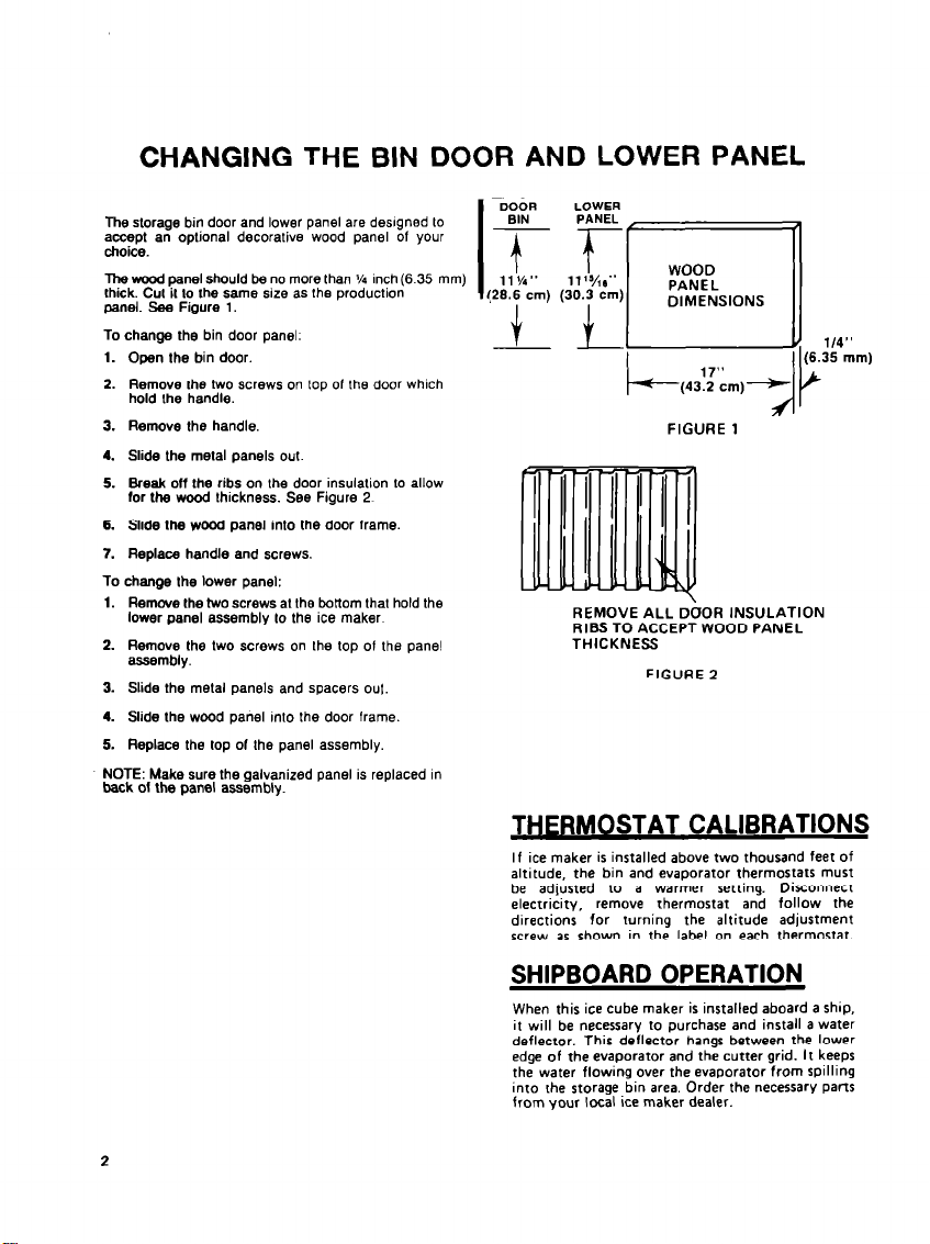
The slorage bin door and lower panel are deslgned to
accept an oplional decorative wood panel of your
choice.
The wood panel should be no more than j/4 Inch (6.35 mm)
Ihick. GUI il lo the same size as Ihe production
panel. See Figure 1.
To change the bin door panel.
1. Open the bin door.
2. Remove the two screws on lop of the door which
hold Ihe handle.
3. Remove the handle.
4. Slide the metal panels out.
5. Break off the ribs on the door insulalion to allow
for the wood thickness. See Figure 2
6. Slide the wood panel into the door frame.
7. Replace handle and acraws.
To change the lower panel:
-
1. Hemwe the two screws at the txttom that hold the
lower panel assembly to the ice maker
2. Remove the Iwo acraws on the top of the pane!
assembly.
3. Slide the metal panels and spacers 01~1.
4. Slide the wood panel into Ihe door frame.
5. Replace the top of the panel assembly
NOTE: Make sure the galvanized panel is replaced I”
back of the panel assembly.
DOOR
BIN PANEL
Tf
11 %” 11’%8”
I
(28.6 cm) (30.3 cm:
LOWER
PANEL
DIMENSIONS
b(43.2 cm)-
FIGURE 1
REMOVE ALL DOOR INSULATION
RIBS TO ACCEPT WOOD PANEL
THICKNESS
FIGURE 2
If ice maker is installed above two thousand feet of
altitude, the bin and evaporator thermostats must
be adjusted to a warmer setting. Disconnect
electricity,
directions for turning the altitude adjustment
screw as shown in the label on each thermostat.
remove thermostat and follow the
SHIPBOARD OPERATION
When this ice cube maker is installed aboard a ship,
it will be necessary to purchase and install a water
deflector. This deflector hanas between the lower
edge of the evaporator and the cutter grid. It keeps
the water flowing over the evaporator from spilling
into the storage bin area. Order the necessary parts
from your local ice maker dealer.
2
GENERAL INFORMATION
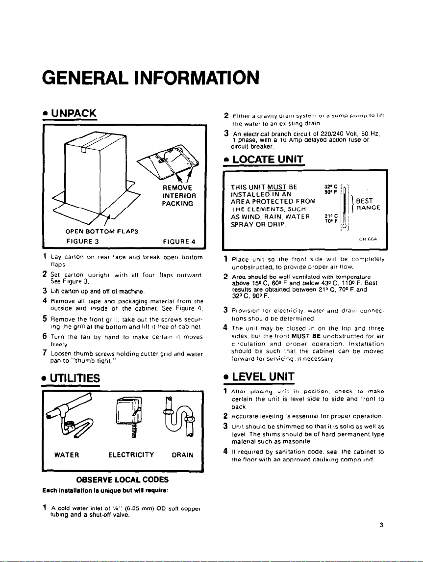
. UNPACK
INTERIOR
OPEN BOTTOM FLAPS
FIGURE 3
1
Lay carlon on rear face and break open botlom
flaps
2
Set carton upnght wlrh all four flaps outward.
See Figure 3.
3 Lift carton up and ott 01 machme.
4
Remove all rape and packaglng material from rhe
outside and lnslde of the cabinet. See Flgure 4.
5R
emove Ihe front grill. lake out the screws secur-
1ng Ihe grlll at the botlom and 1111 It tree 01 c&net
6 Turn the fan by hand lo make terla~n II moves
freely
7 Loosen thumb screws holding cutter grid and water
pan to “thumb right.”
FIGURE 4
. UTILITIES
WATER
ELECTRICITY
DRAIN
2
ElIher a gravely drain
the waler 10 an exlsling drain
3 An eleclr~cal branch cwcuil 01 220/240 Volt, 50 Hz,
1 phase, with a 10 Amp delayed actlon fuse or
circuit breaker.
l
LOCATE UNIT
THIS UNIT MUST BE
INSTALLED IN AN
AREA PROTECTED FROM
THE ELEMENTS, SUCH
AS WIND, RAIN, WATER
SPRAY OR DRIP
1
Place unit so the fronl side WIII be complelely
unobstructed, to provide Draper air flow.
2 Area should be well ventllaled wth temperature
above 150 C, 600 F and below 430 C. 1100 F. Best
results are obtained between 210 C. 700 F and
320 C. 900 F.
3
Prov~slon lor eleclr#city water and drain conneclions should be delermlned.
4
The unit may be closed in on Ihe top and lhree
sndes. bul Ihe Iron1 MUST BE u”obs,r”c,ed lor air
circulalion and proper operalion. Inslallalion
should be such lhal Ihe cabinel can be moved
lorward lor servicing il
Syslem
or a sump pump t0 1111
necessary
. LEVEL UNIT
1 After placing unit in powlion. check to make
certain the unit IS level side lo side and front 10
back
2
Accurate leveling 1s eSsenlIal for proper OperaliOn.
3 Unit should be shimmed so that it !s solld as well as
level The shims should be of hard permanenl type
malerlal such as masonate
4 If required by sanitation code. seal rhe cabinet to
I
Ihe floor wlh an approved Caulking compound
OBSERVE LOCAL CODES
Emch installation 1~ unique but will require:
1
A cold water Inlet of l/4” (6.35 mm) OD
tubing and a shut-off valve.
sdi copper
3
 Loading...