

KitchenAid 3186523 User Manual
HOME APPLIANCES
Installation Instructions
Create-a-Cooktop
IMPORTANT:
Read and save these
instructions.
Part No. 3186523 Rev. D
Important:
Installer: Leave Installation Instructions with the homeowner.
Homeowner: Keep Installation Instructions for future reference.
Save Installation Instructions for local electrical inspector’s use.
Write down the model and serial numbers before installing
cooktop.
Both numbers are on the model/serial rating plate, located on
the bottom of cooktops and grills and on the right side, above
the wiring box on the downdraft vent blower box.
7-98
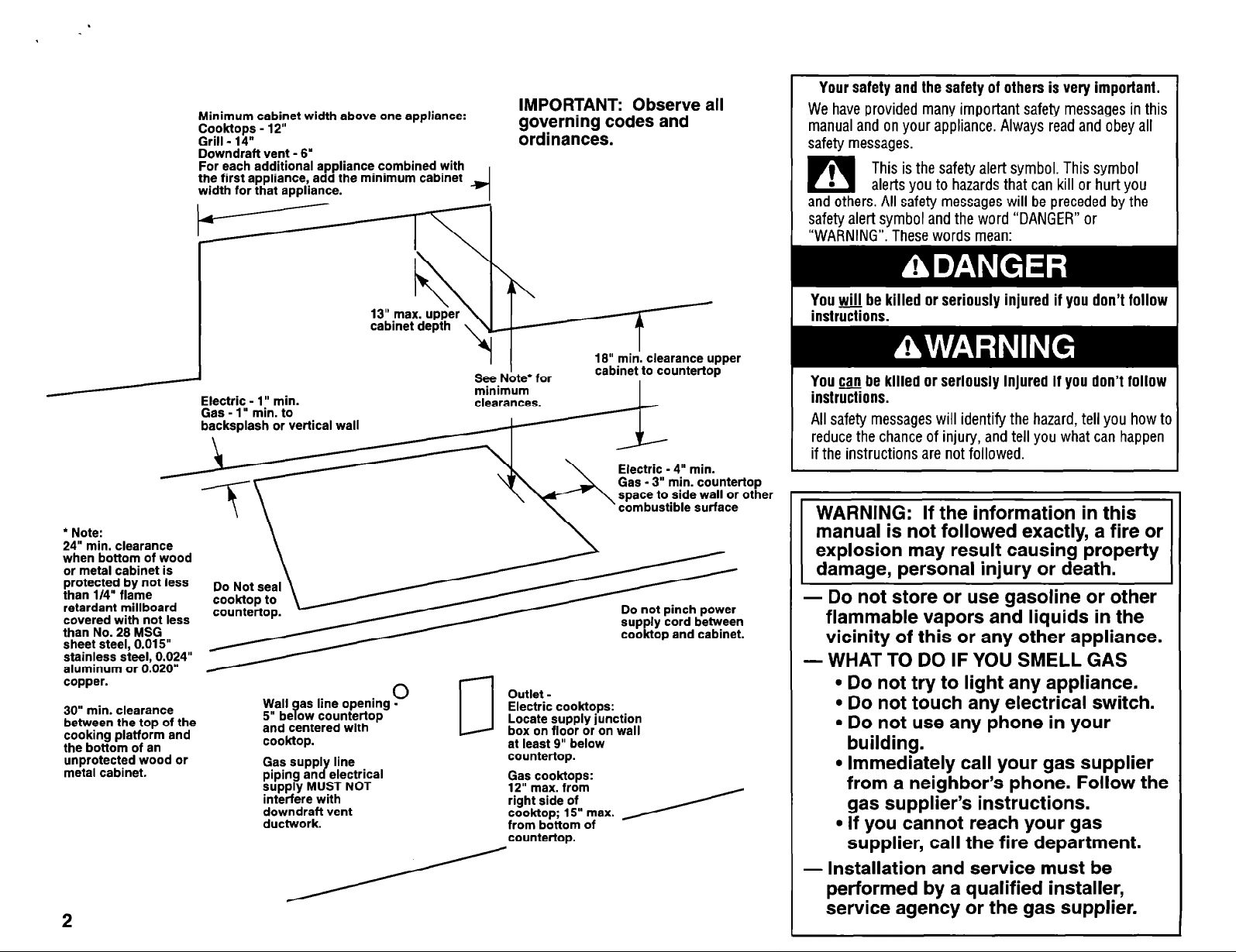
Minimum cabiret width above one appliance:
g?$y;f - ‘2
-
Downdraft vent - 6’
For each additional appliance combined with
the first appliance, add the minimum cabinet
width for that appliance.
/Electric - 1” min.
l
Note:
24” min. clearance
when bottom of wood
or metal cabinet is
protected by not less
than l/4” flame
retardant millboard
covered with not less
than No. 28 MSG
sheet steel, 0.015”
stainless steel, 0.024”
aluminum or 0.020”
copper.
30” min. clearance
between the top of the
cooking platform and
the bottom of an
unprotected wood or
metal cabinet.
Gas-l’ ” min. to
lash or vertical wall
backsp
u
Wall
5” be ow countertop
and centered with
cook-top.
Gas supply line
piping and electrical
supply MUST NOT
interfere with
~;;~drlrf vent
/ .
2
cabinet depth 1
as line opening -
9
0 -
IMPORTANT: Observe all
governing codes and
ordinances.
S$e.Note* for
mimmum
Outlet Electric cooktops:
Locate supply junction
LJ
box on floor or on wall
at least 9” below
countertop.
Gas cooktops:
12” max from
right side of
cook-top; 15” max.
from bottom of
countertop.
I
18” min. clearance upper
cabinet to countertop
I
Electric - 4” min.
Gas - 3” min. countertop
space to side wall or other
combustible surface
supply cord between
cooktop and cabinet.
Your safety and the safety of others is very important.
We have provided many important safety messages in this
manual and on your appliance. Always read and obey all
safety messages.
This is the safety alert symbol. This symbol
alerts you to hazards that can kill or hurt you
and others. All safety messages will be preceded by the
safety alert symbol and the word “DANGER” or
“WARNING”. These words mean:
You will be killed or seriously injured if you don’t follow
instrG3ons.
You can be killed or seriously injured if you don’t follow
instrZions.
All safety messages will identify the hazard, tell you how ta
reduce the chance of injury, and tell you what can happen
if the instructions are not followed.
WARNING: If the information in this
- Do not store or use gasoline or other
flammable vapors and liquids in the
vicinity of this or any other appliance.
-WHAT TO DO IF YOU SMELL GAS
l
Do not try to light any appliance.
l
Do not touch any electrical switch.
l
Do not use any phone in your
building.
l
Immediately call your gas supplier
from a neighbor’s phone. Follow the
gas supplier’s instructions.
l
If you cannot reach your gas
supplier, call the fire department.
- Installation and
service must be
performed by a qualified installer,
service agency or the gas supplier.
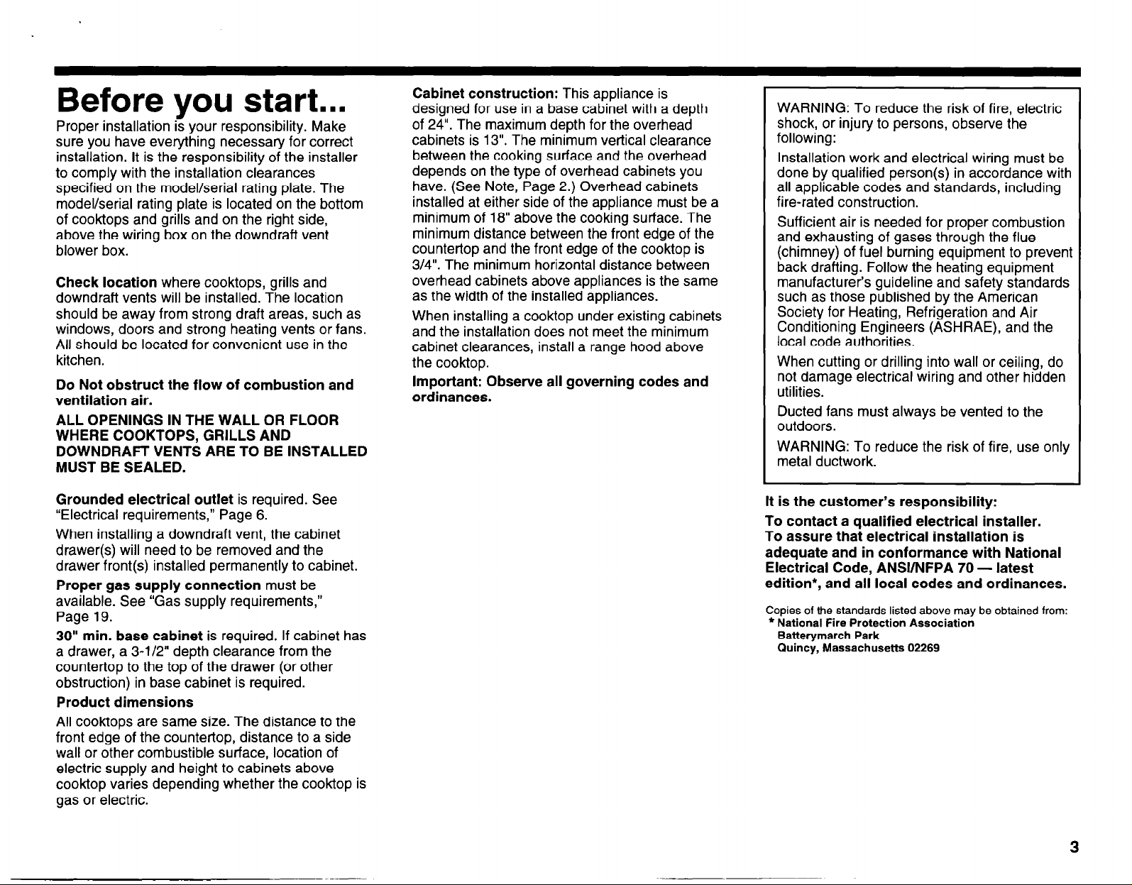
Before vou start...
Proper installation iz your responsibility. Make
sure you have everything necessary for correct
installation. It is the responsibility of the installer
to comply with the installation clearances
specified on the model/serial rating plate. The
model/serial rating plate is located on the bottom
of cooktops and grills and on the right side,
above the wiring box on the downdraft vent
blower box.
Check location where cooktops, grills and
downdraft vents will be installed. The location
should be away from strong draft areas, such as
windows, doors and strong heating vents or fans.
All should be located for convenient use in the
kitchen.
Do Not obstruct the flow of combustion and
ventilation air.
ALL OPENINGS IN THE WALL OR FLOOR
WHERE COOKTOPS, GRILLS AND
DOWNDRAFT VENTS ARE TO BE INSTALLED
MUST BE SEALED.
Cabinet construction: This appliance is
designed for use in a base cabinet with a depth
of 24”. The maximum depth for the overhead
cabinets is 13”. The minimum vertical clearance
between the cooking surface and the overhead
depends on the type of overhead cabinets you
have. (See Note, Page 2.) Overhead cabinets
installed at either side of the appliance must be a
minimum of 18” above the cooking surface. The
minimum distance between the front edge of the
countertop and the front edge of the cooktop is
3/4”. The minimum horizontal distance between
overhead cabinets above appliances is the same
as the width of the installed appliances.
When installing a cooktop under existing cabinets
and the installation does not meet the minimum
cabinet clearances, install a range hood above
the cooktop.
Important: Observe all governing codes and
ordinances.
WARNING: To reduce the risk of fire, electric
shock, or injury to persons, observe the
following:
Installation work and electrical wiring must be
done by qualified person(s) in accordance with
all applicable codes and standards, including
fire-rated construction.
Sufficient air is needed for proper combustion
and exhausting of gases through the flue
(chimney) of fuel burning equipment to prevent
back drafting. Follow the heating equipment
manufacturer’s guideline and safety standards
such as those published by the American
Society for Heating, Refrigeration and Air
Conditioning Engineers (ASHRAE), and the
local code authorities.
When cutting or drilling into wall or ceiling, do
not damage electrical wiring and other hidden
utilities.
Ducted fans must always be vented to the
outdoors.
WARNING: To reduce the risk of fire, use only
metal ductwork.
Grounded electrical outlet is required. See
“Electrical requirements,” Page 6.
When installing a downdraft vent, the cabinet
drawer(s) will need to be removed and the
drawer front(s) installed permanently to cabinet.
Proper gas supply connection must be
available. See “Gas supply requirements,”
Page 19.
30” min. base cabinet is required. If cabinet has
a drawer, a 3-l/2” depth clearance from the
countertop to the top of the drawer (or other
obstruction) in base cabinet is required.
Product dimensions
All cooktops are same size. The distance to the
front edge of the countertop, distance to a side
wall or other combustible surface, location of
electric supply and height to cabinets above
cooktop varies depending whether the cooktop is
gas or electric.
It is the customer’s responsibility:
To contact a qualified electrical installer.
To assure that electrical installation is
adequate and in conformance with National
Electrical Code, ANSYNFPA 70 - latest
edition*, and all local codes and ordinances.
Copies of the standards listed above may be obtained from:
* National Fire Protection Association
Batterymarch Park
Quincy, Massachusetts 02269
3
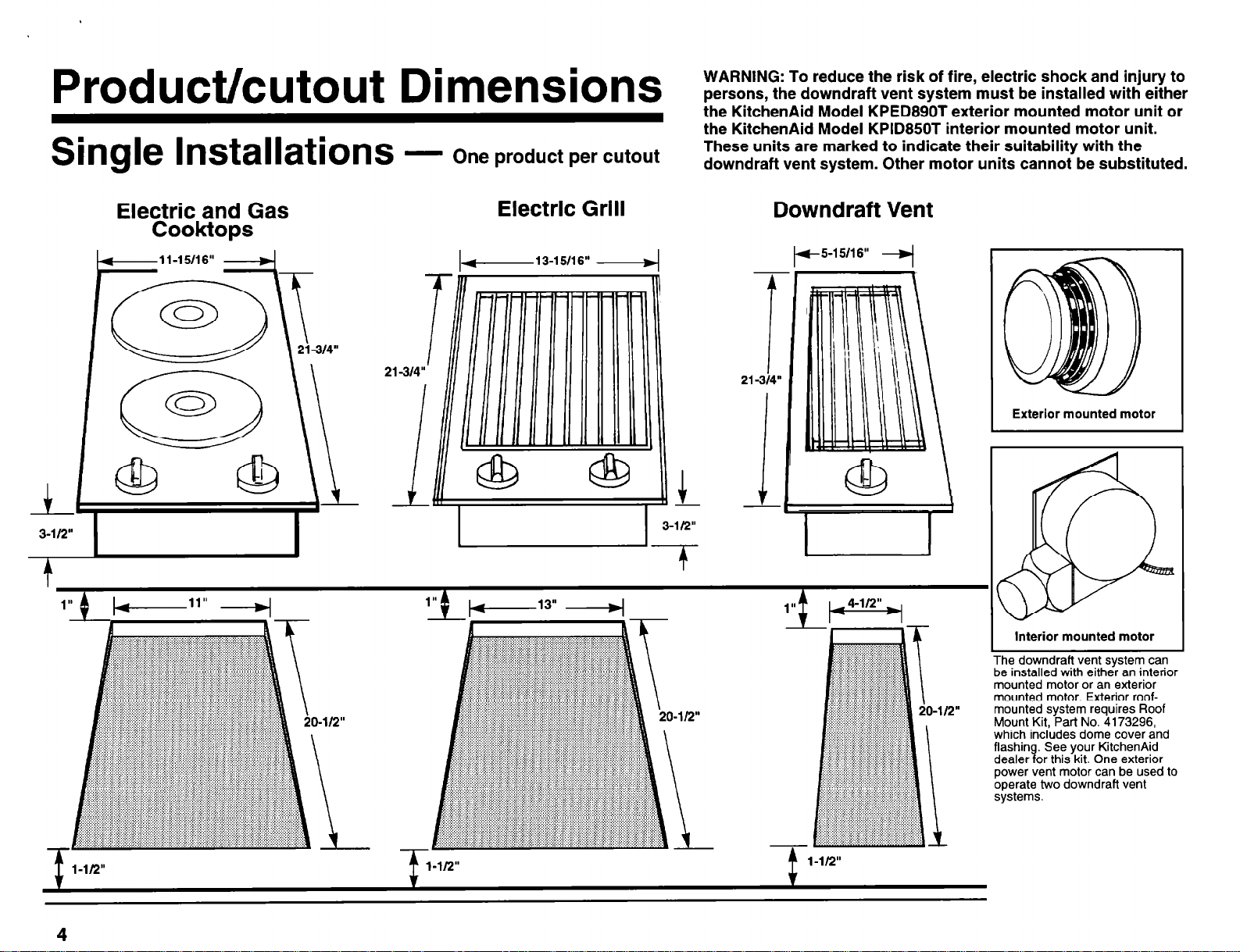
Product/cutout Dimensions
Single Installations -
One product per cutout
WARNING: To reduce the risk of fire, electric shock and injury to
persons, the downdraft vent system must be installed with either
the KitchenAid Model KPED890T exterior mounted motor unit or
the KitchenAid Model KPID850T interior mounted motor unit.
These units are marked to indicate their suitability with the
downdraft vent system. Other motor units cannot be substituted.
Electk$;dpsGas Electk$;dpsGas
21314”
Electric Grill
I-
-1.
i
13-l 5/l 6” .-d
Downdraft Vent
#-5-15/16”
-i
Exterior mounted motor
Interior mounted motor
he downdrafl vent system can
b le Installed with either an lnlerlor
mounted motor or an exterior
mounted motor. Exterior roofmounted system requires Roof
Mount Kit, Part No. 4173296,
which includes dome cover and
flashing. See your KitchenAid
dealer for this kit. One exterior
power vent motor can be used to
operate two downdraft vent
systems.
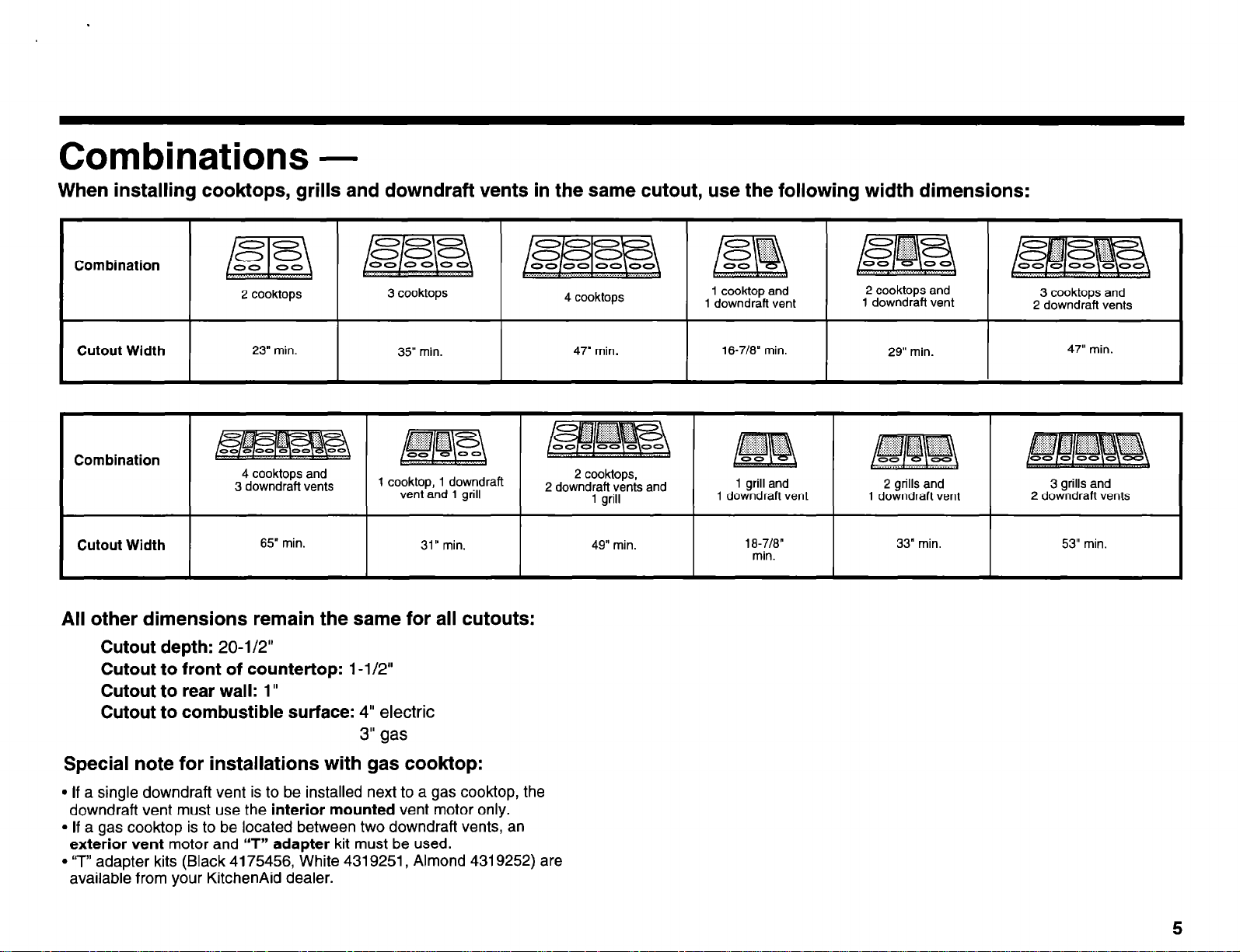
Combinations -
When installing cooktops, grills and downdraft vents in the same cutout, use the following width dimensions:
Combination
I
2 cooktops
3 cooktops
I
I
4 cooktops
1 cooktop and
1 downdraft vent
2 cooktops and
I
1 downdraft vent
I
3 cooktops and
2 downdraft vents
Cutout Width
I
Combination
Cutout Width
r
4 cooktops and
3 downdraft vents
35” min.
1 cooktop, 1 downdraft
vent and 1 grill
All other dimensions remain the same for all cutouts:
Cutout depth: 20-l/2”
Cutout to front of countertop: 1 -l/2”
Cutout to rear wall: 1”
Cutout to combustible surface: 4” electric
3” gas
Special note for installations with gas cooktop:
9 If a single downdraft vent is to be installed next to a gas cooktop, the
downdraft vent must use the interior mounted vent motor only.
l
If a gas
exterior vent motor and ‘IT” adapter kit must be used.
l
‘7” adapter kits (Black 4175456, White 4319251, Almond 4319252) are
available from your KitchenAid dealer.
cooktop
is to be located between two downdraft vents, an
2 cooktops,
2 downdraft vents
1 grill
49” min.
16-7/e” min.
I
and 1 grill and
1 downdraft vent
1 e-7/8”
min.
I
29” min.
2 grills and
1 downdraft vent
3 grills and
2 downdraft vents
5
Tools/Parts
Electric Cooktop and Grill
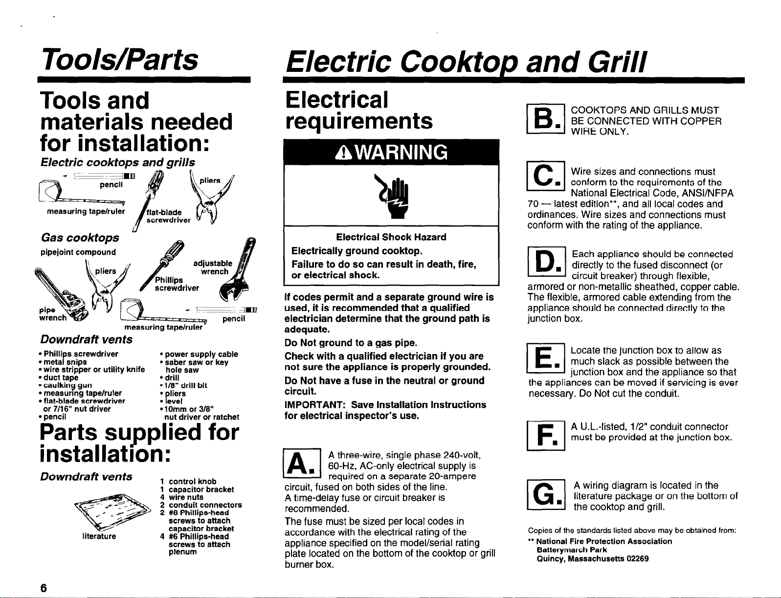
Tools and
materials needed
for installation:
Electric cooktops and grills
Ll
Gas cooktops
pipejoint compound
measuring tape/ruler’
Downdraft vents
l
l
Phillips screwdriver
l
metal snips
l
wire stripper or utility knife
l
duct tape
l
caulking gun
l
measurmg tape/ruler
l
flat-blade screwdriver
or 7/16” nut driver
l
pencil
power supply cable
l
saber saw or key
hole saw
l
drill
*l/8” drill bit
l
liers
P
l
evel
l
1 Omm or 318”
nut driver or ratchet
Parts supplied for
installatron:
Downdraft vents
literature
1 control knob
1 caoacitor bracket
4 wire nuts
2 conduit connectors
2 #8 Phillips-head
screws to attach
capacitor bracket
4 #6 Phillips-head
screws to attach
plenum
Electrical requirements
I
l!%l
El
70ordinances. Wire sizes and connections must
conform with the rating of the appliance.
•l
armored or non-metallic sheathed, copper cable.
If codes permit and a separate ground wire is
used, it is recommended that a qualified
electrician determine that the ground path is
adequate.
Do Not ground to a gas pipe.
Check with a qualified electrician if you are
not sure the appliance is properly grounded.
Do Not have a fuse in the neutral or ground
circuit.
IMPORTANT: Save Installation Instructions
for electrical inspector’s use.
A three-wire, single phase 240-volt,
60-H& AC-only electrical supply is
n
/A
circuit, fused on both sides of the line.
A time-delay fuse or circuit breaker is
recommended.
The fuse must be sized per local codes in
accordance with the electrical rating of the
appliance specified on the model/serial rating
plate located on the bottom of the cook-top or grill
burner box.
required on a separate 20-ampere
The flexible, armored cable extending from the
appliance should be connected directly to the
junction box.
El
the appliances can be moved if servicing is ever
necessary. Do Not cut the conduit.
El
El
Copies of the standards listed above may be obtained from:
** National Fire Protection Association
Batterymarch Park
Quincy, Massachusetts 02269
COOKTOPS AND GRILLS MUST
BE CONNECTED WITH COPPER
WIRE ONLY.
Wire sizes and connections must
n
conform to the requirements of the
National Electrical Code, ANSVNFPA
latest edition**,
Each appliance should be connected
. directly to the fused disconnect (or
circuit breaker) through flexible,
Locate the junction box to allow as
n
much slack as possible between the
iunction box and the appliance so that
A U.L.-listed, l/2” conduit connector
must be provided at the junction box.
A wiring diagram is located in the
literature package or on the bottom of
.
the cooktop and grill.
. . . . .
and all local
COdeS and
6
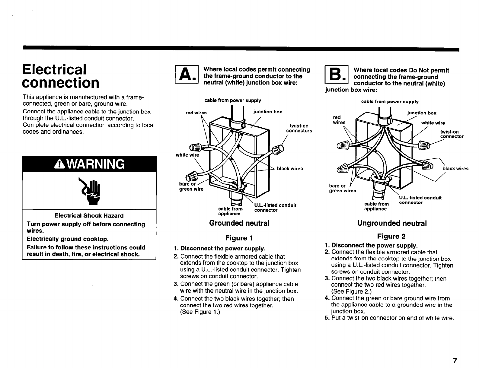
Electrical
connection
This appliance is manufactured with a frameconnected, green or bare, ground wire.
Connect the appliance cable to the junction box
through the U.L.-listed conduit connector.
Complete electrical connection according to local
codes and ordinances.
Where local codes permit connecting
the frame-ground conductor to the
neutral (white) junction box wire:
cable from power supply
red wires
I I
junction box
twist-on
connectors
Where local codes Do Not permit
El
junction box wire:
connecting the frame-ground
.
conductor to the neutral (white)
cable from power supply
ist-on
nnector
Electrical Shock Hazard
Turn power supply off before connecting
wires.
Electrically ground cooktop.
Failure to follow these instructions could
result in death, fire, or electrical shock.
2 black wires
cable from
appliance
’ U.L.-listed conduit
connector
Grounded neutral
Figure 1
1. Disconnect the power supply.
2. Connect the flexible armored cable that
extends from the cooktop to the junction box
using a U.L.-listed conduit connector. Tighten
screws on conduit connector.
3. Connect the green (or bare) appliance cable
wire with the neutral wire in the junction box.
4. Connect the two black wires together; then
connect the two red wires together.
(See Figure 1.)
black wires
U.L.-listed conduit
cable from
appliance
connector
Ungrounded neutral
Figure 2
1. Disconnect the power supply.
2. Connect the flexible armored cable that
extends from the cooktop to the junction box
using a U.L.-listed conduit connector. Tighten
screws on conduit connector.
3. Connect the two black wires together; then
connect the two red wires together.
(See Figure 2.)
4. Connect the green or bare ground wire from
the appliance cable to a grounded wire in the
junction box.
5. Put a twist-on connector on end of white wire.
7
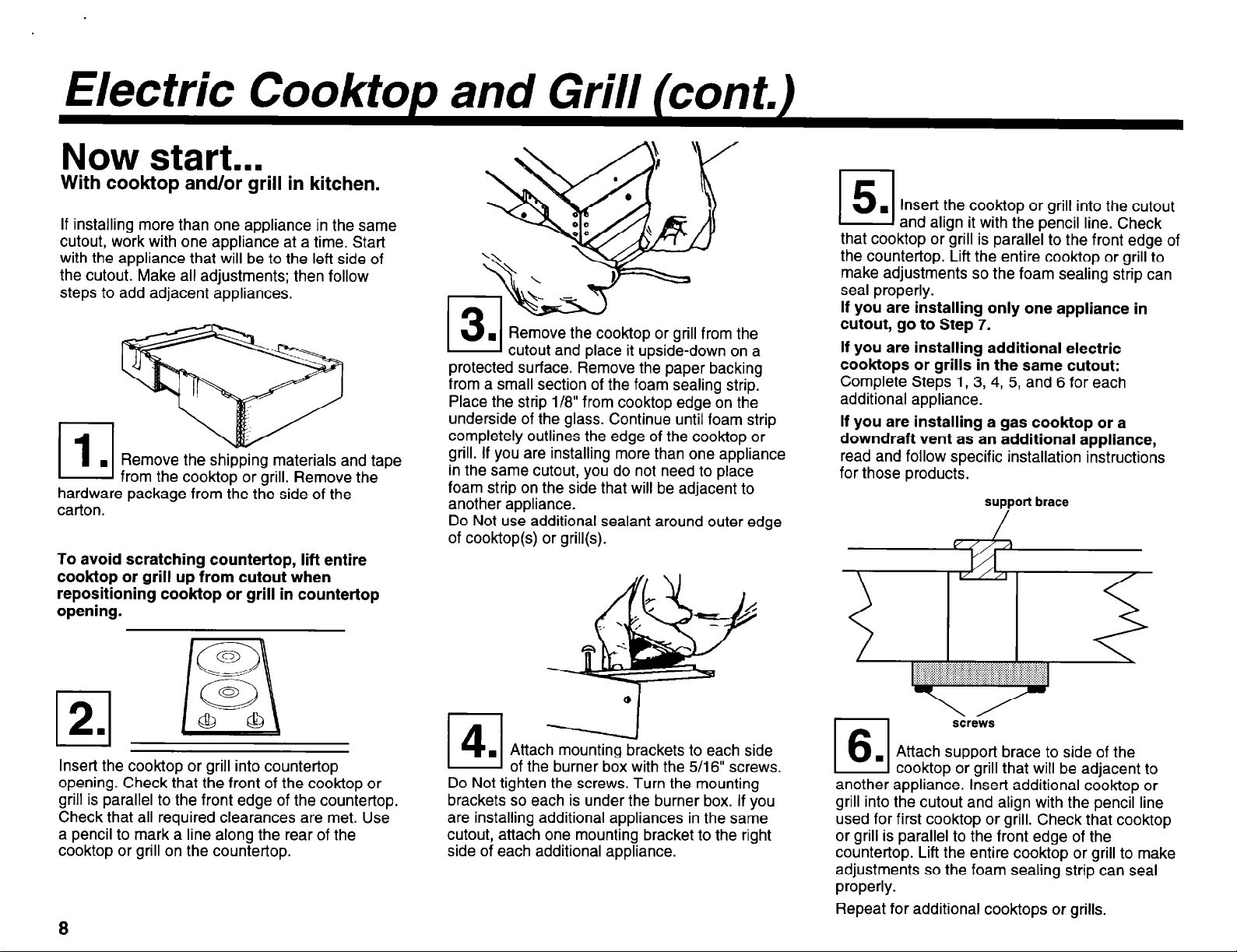
Electric Cooktop and Grill (cont.)
Now start...
With
cooktop
If installing more than one appliance in the same
cutout, work with one appliance at a time. Start
with the appliance that will be to the left side of
the cutout. Make all adjustments; then follow
steps to add adjacent appliances.
Remove the shipping materials and tape
from the cooktop or grill. Remove the
hardware package from the the side of the
carton.
To avoid scratching countertop, lift entire
cooktop or grill up from cutout when
repositioning cooktop or grill in countertop
opening.
and/or grill in kitchen.
Remove the cook-top or grill from
cutout and place it upside-down on a
protected surface. Remove the paper backing
from a small section of the foam sealing strip.
Place the strip l/8” from cooktop edge on the
underside of the glass. Continue until foam strip
completely outlines the edge of the cooktop or
grill. If you are installing more than one appliance
in the same cutout, you do not need to place
foam strip on the side that will be adjacent to
another appliance.
Do Not use additional sealant around outer edge
of cooktop or grill(s).
the
151
that cooktop or grill is parallel to the front edge of
the countertop. Lift the entire cooktop or grill to
make adjustments so the foam sealing strip can
seal properly.
If you are installing only one appliance in
cutout, go to Step 7.
If you are installing additional electric
cooktops or grills in the same cutout:
Complete Steps 1, 3, 4, 5, and 6 for each
additional appliance.
If you are installing a gas cooktop or a
downdraft vent as an additional appliance,
read and follow specific installation instructions
for those products.
and align it with the pencil line. Check
support brace
/
I
1/
Insert the cooktop or grill into the cutout
n
Insert the cooktop or grill into countertop
opening. Check that the front of the cooktop or
grill is parallel to the front edge of the countertop.
Check that all required clearances are met. Use
a pencil to mark a line along the rear of the
cooktop or grill on the countertop.
8
Attach mounting brackets to each side
of the burner box with the 5/16” screws.
Do Not tighten the screws. Turn the mounting
brackets so each is under the burner box. If you
are installing additional appliances in the same
cutout, attach one mounting bracket to the right
side of each additional appliance.
I
another appliance. l&en additional cook-top or
grill into the cutout and align with the pencil line
used for first cooktop or grill. Check that cooktop
or grill is parallel to the front edge of the
countertop. Lift the entire cooktop or grill to make
adjustments so the foam sealing strip can seal
properly.
Repeat for additional cooktops or grills.
I s&ws
Attach support brace to side of the
CooktoD or arill that will be adiacent to
,
 Loading...