

KitchenAid 30"" Freestanding Range, 30"" Slide-in Range Installation Instructions Manual
1
IMPORTANT:
Installer: Leave Installation
Instructions with the homeowner.
Homeowner: Keep Installation
Instructions for future reference.
Read and save these instructions
for local electrical inspector’s use.
Write down the model and serial
numbers before installing range.
Both numbers are listed on the
model/serial rating plate located
on the oven frame behind the
storage drawer panel.
Model # _______________________________
Serial # _______________________________
IMPORTANT:
Read and save these instructions.
9758571
Part No. 9758571
30" (76.2 cm) Sealed Burner Gas Range
with self-cleaning thermal/convection oven
WARNING
Tip Over Hazard
Achild or adult can tip the range and
be killed.
Connect anti-tip bracket to rear
range foot.
Reconnect the anti-tip bracket, if the
range is moved.
Failure to follow these instructions can
result in death or serious burns to
children and adults.
®
HOME APPLIANCES
www.kitchenaid.com
Installation Instructions
Freestanding
Range
Slide-in
Range
Quick Reference
Ta ble of Contents:
Pages
2
3
4
5
6
Before you start
Electrical requirements
Gas supply requirements
Product dimensions
Cabinet dimensions/requirements
Installation steps
If range does not operate
Moving the range
If you need assistance/service
7- 10
10
10
11
9758571
2
Before you start...
Copies of the standards listed may be obtained
from:
* CSA International
8501 East Pleasant Valley Rd.
Cleveland, Ohio 44131-5575
** National Fire Protection Association
One Batterymarch Park
Quincy, Massachusetts, 02269
WARNING
Your safety and the safety of
others are very important.
You can be killed or seriously injured
if you don't follow
instructions.
You can be killed or seriously injured
if you don't follow instructions.
We have provided many important safety
messages in this manual and on your
appliance.Always read and obey all
safety messages.
This is the safety alert symbol.
This symbol alerts you to
potential hazards that can kill
or hurt you and others.
All safety messages will follow the safety
alert symbol and either the word
“DANGER”or “WARNING.”These
words mean:
All safety messages will tell you what the
potential hazard is, tell you how to
reduce the chance of injury,and tell you
what can happen if the instructions are
not followed.
immediately
DANGER
— Do not store or use
gasoline or other
flammable vapors and
liquids in the vicinity of
this or any other
appliance.
— WHAT TO DO IF YOU
SMELL GAS
• Do not try to light any
appliance.
• Do not touch any
electrical switch.
• Do not use any phone in
your building.
• Immediately call your
gas supplier from a
neighbor’s phone.
Follow the gas
supplier’s instructions.
• If you cannot reach your
gas supplier, call the fire
department.
— Installation and service
must be performed by a
qualified installer, service
agency or the gas supplier.
WARNING: If the
information in this manual
is not followed exactly,
a fire or explosion may
result causing property
damage, personal injury
or death.
IMPORTANT: Observe all governing
codes and ordinances.
Do not obstruct flow of combustion and
ventilation air.
This installation must conform with
all local codes and ordinances. In the
absence of local codes, installation
must conform with American National
Standard, National Fuel Gas Code ANSI
Z223.1 — latest edition* installation
codes.
It is the customer’s responsibility:
• To contact a qualified electrical installer.
• To assure that the electrical installation
is adequate and in conformance with
National Electrical Code, ANSI/NFPA 70
— latest edition**, and all local codes
and ordinances.
Proper installation is your responsibility.
A qualified technician must install this
range. Make sure you have everything
necessary for correct installation. It is the
installer’s responsibility to comply with
installation clearances specified on the
gas information label. The gas
information label and model/serial rating
plate are located on the frame behind the
storage drawer.
Check location where range will be
installed. The range should be located for
convenient use in kitchen. Recessed
installations must provide complete
enclosure of the sides and rear of range.
All openings in the wall or floor where
range is to be installed must be sealed.
To eliminate the risk of burns or fire by
reaching over heated surface units,
cabinet storage space located above the
surface units should be avoided. If
cabinet storage is to be provided, the risk
can be reduced by installing a range
hood that projects horizontally a
minimum of 5 inches beyond the bottom
of the cabinets.
Cabinet opening dimensions that are
shown must be used. Given dimensions
are minimum clearances.
Mobile home installation
The installation of this range must
conform to the Manufactured Home
Construction and Safety Standards, Title
24 CFR, Part 3280 (formerly the Federal
Standard for Mobile Home construction
and Safety, Title 24, HUD, Part 280); or
when such standard is not applicable, the
Standard for Manufactured Homes
Installations (Manufactured Home Sites,
Communities and Setups), ANSI
A225.1/NFPA 501A**, or with local codes.
In Canada, the installation of this range
must conform with the current standards
CAN/CSA-Z240 — latest edition*, or with
local codes.
When this range is installed in a mobile
home, it must be secured to the floor
during transit. Any method of securing
the range is adequate as long as it
conforms to the standards listed above.
3
Tools needed:
Assemble the required tools and parts
before starting installation. Read and
follow the instructions provided with any
tools listed here.
• level
• flat-blade screwdriver
• Phillips screwdriver
• putty knife
• pipe wrench
• 3/8" drive ratchet
• 3/8" and 5/16" combination wrenches
• hand or electric drill
• channel lock pliers
• measuring tape or ruler
• wood floors: 1/8" drill bit
• concrete/ceramic floors:
3/16" carbide-tipped masonry drill bit
(Hammer may be needed for anchors.)
Materials needed:
• gas line shutoff valve
• 1/2" male pipe thread nipple for connection
to pressure regulator
• L.P. gas-resistant pipe-joint compound
• AGA or CSA design-certified flexible metal
appliance connector (4-5 feet) (1.2-1.5 m) or
rigid gas supply line as needed
• Insulated pad or 1/4" (6 mm) plywood if
range is installed over carpeting
• burner grates and caps
• vent cap
• L.P conversion orifice spud kit:
1 – 0.95 mm cooktop (blue)
2 – 0.67 mm cooktop (black)
1 – 1.05 mm cooktop (green)
1 – #65 broil burner
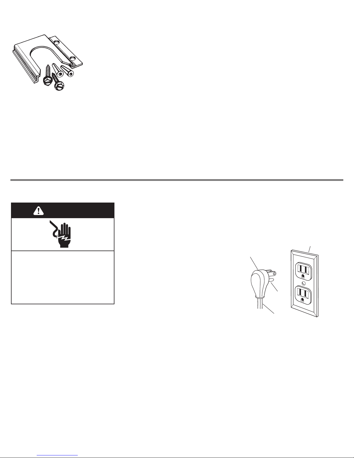
Parts supplied:
2 plastic
anchors
floor-mounted
anti-tip bracket
Not shown:
• literature pack
• orifice spuds
2 screws
(#10 x 1-1/2")
Bracket must be securely mounted to sub-floor.
Thickness of flooring may require longer screws to
anchor bracket to sub-floor. Longer screws are
available from your local hardware store.
Electrical requirements
Electrical Shock Hazard
Plug into a grounded 3 prong outlet.
Do not remove ground prong.
Do not use an adapter.
Do not use an extension cord.
Failure to follow these instructions can
result in death, fire, or electrical shock.
WARNING
Copies of the standards listed may be obtained
from:
* National Fire Protection Association
One Batterymarch Park
Quincy, Massachusetts, 02269
** CSA International
8501 East Pleasant Valley Rd.
Cleveland, Ohio 44131-5575
If codes permit and a separate ground
wire is used, it is recommended that a
qualified electrician determine that the
ground path is adequate and that the
outlet is correctly polarized.
Do not ground to a gas pipe.
Check with a qualified electrician if you
are not sure range is properly grounded.
A 120-volt, 60-Hz, AC-only, 10-ampere,
fused electrical supply is required. A
time-delay fuse or circuit breaker is
recommended. It is recommended that a
separate circuit serving only this
appliance be provided.
Recommended ground
method
For personal safety, this range is
equipped with a power supply cord
having a 3 prong ground plug. To
minimize possible shock hazard, the cord
must be plugged into a mating 3 prong,
ground-type outlet, grounded in
accordance with the National Electrical
Code, ANSI/NFPA 70 — latest edition*, or
CSA Standard C22.1 Canadian Electrical
Code, Part 1 — latest edition**, and all
local codes and ordinances.
3 prong properly polarized
ground-type outlet
3 prong
ground plug
ground
prong
power supply
cord
Electronic ignition systems operate
within wide voltage limits, but proper
grounding and polarity are necessary.
In addition to checking that the outlet is
correctly grounded, the outlet must be
checked by a qualified electrician to see if
it is wired with correct polarity.
IMPORTANT:This range is equipped with
an electronic ignition system that will not
operate if plugged into an outlet that is
not properly polarized.
A wiring diagram is included on the back
of the range.
See “Cabinet dimensions/requirements”
for recommended location of electrical
outlet.
If a mating outlet is not available, it is the
personal responsibility and obligation of
the customer to have a properly
polarized and grounded, 3 prong outlet
installed by a qualified electrician.
4
Gas supply requirements
WARNING
Explosion Hazard
Use a new AGA or CSA approved gas
supply line.
Install a shutoff valve.
Securely tighten all gas connections.
If connected to LP, have a qualified
person make sure gas pressure does
not exceed 14" (35.6 cm) water column.
Examples of a qualified person
include:
licensed heating personnel,
authorized gas company
personnel, and
Failure to do so can result in death,
explosion, or fire.
authorized service personnel.
In the State of Massachusetts, the
following installation instructions
apply:
• Installations and repairs must be
performed by a qualified or licensed
contractor, plumber, or gasfitter
qualified or licensed by the State
of Massachusetts.
• If using a ball valve, it shall be a
T-handle type.
• A flexible gas connector, when used,
must not exceed 3 feet.
Observe all governing codes and
ordinances.
This installation must conform with local
codes and ordinances. In the absence of
local codes, installations must conform
with American National Standard,
National Fuel Gas Code ANSI Z223.1 —
latest edition*.
Input ratings shown on the model/serial
rating plate are for elevations up to 2,000
feet (610 m). For assistance when
installing the range at higher elevations,
contact your local service company.
Type of gas: This range is designcertified by CSA International for use
with Natural gas or, after proper
conversion, for use with L.P. gas. This
range is factory set for use with Natural
gas. Gas conversion instructions are
provided in “Gas conversions” section.
The model/serial rating plate located on
the frame behind the storage drawer or
broiler door has information on the type
of gas that can be used. If the type of
gas listed does not agree with the type of
gas available, check with the local gas
supplier. Conversion must be done by a
qualified service technician.
Gas supply line: Provide a gas supply
line of 3/4" rigid pipe to the range
location. With L.P. gas, piping or tubing
size can be 1/2" minimum. A smaller size
pipe on longer runs may result in
insufficient gas supply. Usually, L.P. gas
suppliers determine the size and
materials used in the system.
Pipe-joint compounds made for use with
L.P. gas must be used on pipe threads
only.
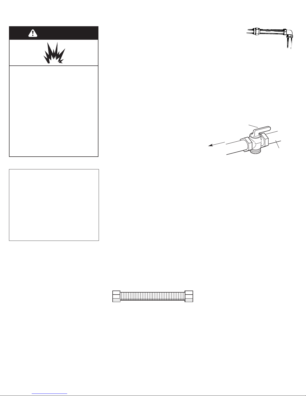
Flexible metal appliance connector: If
local codes permit, a new AGA or CSA
design-certified, 1/2" or 3/4" I.D., flexible
metal appliance connector is
recommended for connecting range to
the gas supply line. A 1/2" male pipe
thread nipple is needed for connection to
pressure regulator female pipe threads.
Do not kink or damage the flexible metal
tubing when moving the range.
Rigid pipe
connection:
Requires a
combination of
pipe fittings to
obtain an in-line connection to the range.
All strains must be removed from the
supply and fuel lines so range will be
level and in line.
Shutoff valve: The supply line must be
equipped with a manual shutoff valve.
This valve should be located in the same
room as the range and should be in a
location that allows ease of opening and
closing. The valve is for turning on or
shutting off gas to the range. Do not
block access to shutoff valve.
Pressure regulator: The gas pressure
regulator supplied with this range must
be used. The inlet pressure to the
regulator should be as follows for proper
operation:
NATURAL GAS:
Minimum pressure: 5 inches W.C.
Maximum pressure: 14 inches W.C.
L.P. GAS:
Minimum pressure: 10 inches W.C.
Maximum pressure: 14 inches W.C.
Contact local gas supplier if you are not
sure about the inlet pressure.
Line pressure testing above 1/2 psi gauge
(14" WCP) — The range and its individual
manual shutoff valve must be
disconnected from the gas supply piping
system during any pressure testing of
that system at test pressures greater than
1/2 psig (3.5 kPa).
Line pressure testing at 1/2 psi gauge
(14" WCP) or lower — The range must be
isolated from the gas supply piping
system by closing its individual manual
shutoff valve during any pressure testing
of that system at test pressures equal to
or less than 1/2 psig (3.5 kPa).
Copies of the standards listed may be obtained
from:
* CSA International
8501 East Pleasant Valley Rd.
Cleveland, Ohio 44131-5575
manual shutoff valve
“open” position
to range
gas supply
 Loading...