

ALL RANGES CAN TIP
l
INJURY TO PERSONS
COULD RESULT
l
INSTALL ANTI-TIP
DEVICE PACKED WITH
RANGE
l
SEE INSTALLATION
INSTRUCTIONS
IMPORTANT:
Read and save
these instructions.
IMPORTANT:
Installer: Leave Installation Instructions with the
homeowner.
Homeowner: Keep Installation Instructions and anti-tip
bracket template for future reference.
Save Installation Instructions for local electrical
inspector’s use.
Part No. 9752387
30” Electric
ding
Before you start...
Read electrical and carpentry instructions.
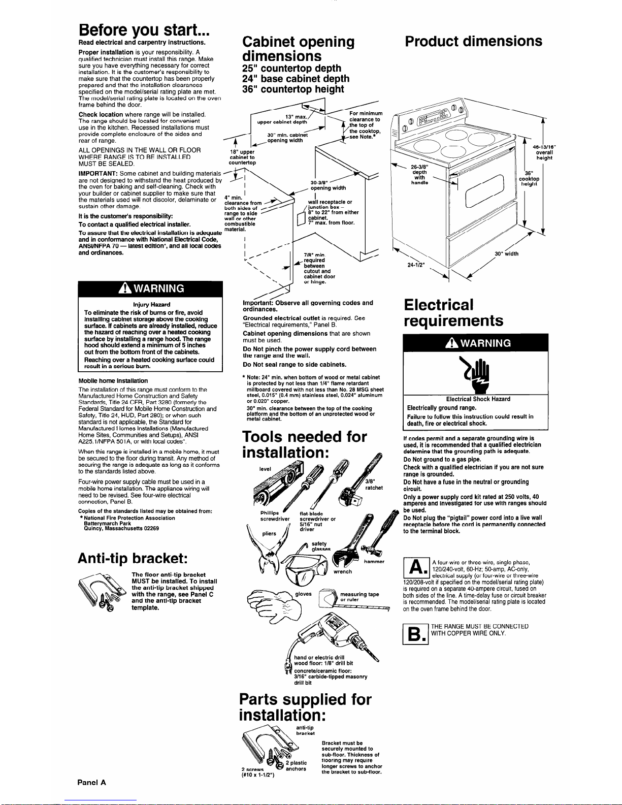
Cabinet opening
Proper installation is your responsibility. A
aualified technician must install this range. Make
dimensions
Product dimensions
sure you have everything necessary for-correct
installation. It is the customer’s responsibility to
make sure that the countertop has been properly
prepared and that the installation clearances
SDecified on the model/serial ratina plate are met.
The model/serial rating plate is Iotated on the oven
frame behind the door.
25” countertop depth
24” base cabinet depth
36” countertop height
Check location where range will be installed.
The range should be located for convenient
use in the kitchen. Recessed installations must
provide complete enclosure of the sides and
rear of range.
ALL OPENINGS IN THE WALL OR FLOOR
WHERE RANGE IS TO BE INSTALLED
16” upper
cabinet to
MUST BE SEALED.
countertop
IMPORTANT: Some cabinet and building materials
are not designed to withstand the heat produced by
the oven for baking and self-cleaning. Check with
your builder or cabinet supplier to make sure that
the materials used will not discolor, delaminate or
sustain other damage.
clearance from
both sides of
It is the customer’s responsibility:
wall or other
d;Rp
handle
‘36”
cooktop
height
opening width
/,dl receptacle or
d
junction box 6” to 22” from either
cabinet,
7” max. from floor.
To contact a qualified electrical installer.
combustible
To assure that the electrical installation is adequate
material.
and in conformance with National Electrical Code,
ANSVNFPA 70 - latest edition*, and all local codes
and ordinances.
I
\
24-112”
Electrical
y required
between
cutout and
cabinet door
or hinge.
Important: Observe all governing codes and
ordinances.
Grounded electrical outlet is required. See
“Electrical requirements,” Panel B.
Cabinet opening dimensions that are shown
must be used.
Do Not pinch the power supply cord between
the range and the wall.
Do Not seal range to side cabinets.
l
Note: 24” min. when bottom of wood or metal cabinet
is protected by not less than l/4” flame retardant
millboard covered with not less than No. 26 MSG sheet
steel, 0.015” (0.4 mm) stainless steel, 0.024” aluminum
or 0.020” copper.
30” min. clearance between the top of the cooking
platform and the bottom of an unprotected wood or
metal cabinet.
Injury Hazard
To eliminate the risk of burns or fire, avoid
installing cabinet storage above the cooking
surface. If cabinets are already installed, reduce
the hazard of reaching over a heated cooking
surface by installing a range hood. The range
hood should extend a minimum of 5 inches
out from the bottom front of the cabinets.
Reaching over a heated cooking surface could
result in a serious burn.
Mobile home installation
The installation of this range must conform to the
Manufactured Home Construction and Safety
Standards, Title 24 CFR, Part 3280 (formerly the
Federal Standard for Mobile Home Construction and
Safety, Title 24, HUD, Part 280); or when such
standard is not applicable, the Standard for
Manufactured Homes Installations (Manufactured
Home Sites, Communities and Setups), ANSI
A225.1/NFPA 501A, or with local codes*.
When this range is installed in a mobile home, it must
be secured to the floor during transit. Any method of
securing the range is adequate as long as it conforms
to the standards listed above.
Four-wire power supply cable must be used in a
mobile home installation. The appliance wiring will
need to be revised. See four-wire electrical
connection, Panel B.
Copies of the standards listed may be obtained from:
l
National Fire Protection Association
Batterymarch Park
Quincy, Massachusetts 02269
requirements
alI
*
Electrical Shock Hazard
Electrically ground range.
Failure to follow this instruction could result in
death, fire or electrical shock.
Tools needed for
installation:
If codes permit and a separate grounding wire is
used, it is recommended that a qualified electrician
determine that the grounding path is adequate.
Do Not ground to a gas pipe.
Check with a qualified electrician if you are not sure
range is grounded.
Do Not have a fuse in the neutral or grounding
circuit.
Only a power supply cord kit rated at 250 volts, 40
amperes and investigated for use with ranges should
be used.
Do Not plug the “pigtail” power cord into a live wall
receptacle before the cord is permanently connected
to the terminal block.
Phillips c
flat-blade
screwdriver or
Anti-tip bracket:
PI
A four-wire or three-wire, single-phase,
. 120/240-volt, 60.Hz; 50.amp, AC-only,
electrical supply (or four-wire or three-wire
120/208-volt if specified on the model/serial rating plate)
is required on a separate 40.ampere circuit, fused on
both sides of the line. A time-delay fuse or circuit breaker
is recommended. The model/serial rating plate is located
on the oven frame behind the door.
The floor anti-tip bracket
MUST be installed. To install
the anti-tip bracket shipped
with the range, see Panel C
and the anti-tip bracket
template.
/B./
THE RANGE MUST BE CONNECTED
WITH COPPER WIRE ONLY.
hand or electric drill
wood floor: l/6” drill bit
concrete/ceramic floor:
3/16” carbide-tipped masonry
drill bit
Parts supplied for
installation:
Bracket must be
securely mounted to
sub-floor. Thickness of
flooring may require
longer screws to anchor
the bracket to sub-floor.
screws
. - . . .-...
2 plastic
anchors
Panel A
 Loading...