

KitchenAid 30” (76.2cm) Installation Instructions Manual
HOME APPLIANCES
Part No. 9751595 Rev. A
1 A
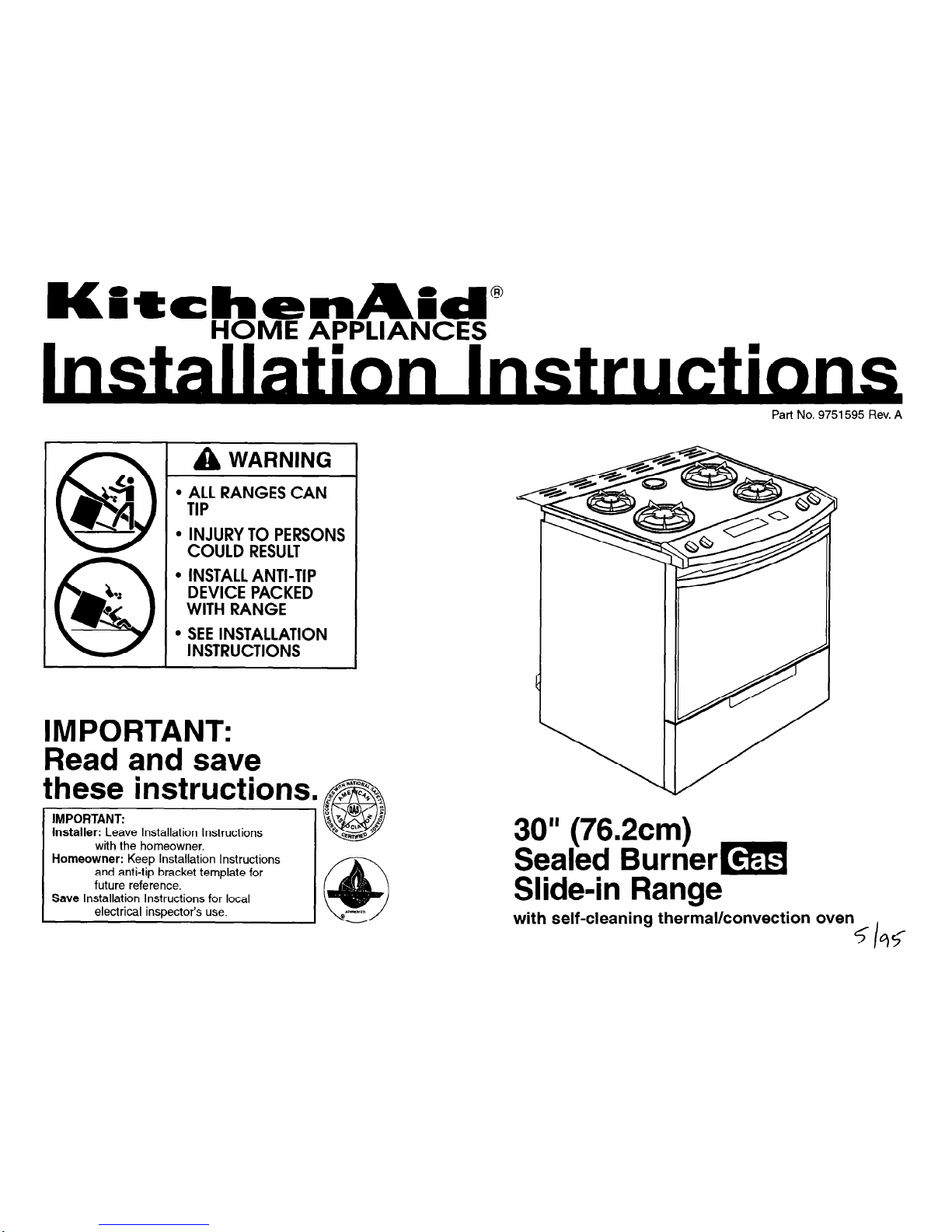
WARNING
l
ALL RANGES CAN
TIP
l
INJURY TO PERSONS
COULD RESULT
l
INSTALL ANTI-TIP
DEVICE PACKED
WITH RANGE
l
SEE INSTALLATION
INSTRUCTIONS
IMPORTANT:
Read and save
these instructions. &F%
\
Installer-
Leave Installation Instructions
Homeowner:
Keep lnstallatibn Instructions
and anti-tip bracket template for
future reference.
Save
Installation Instructions for local
electrical inspector’s use.
30”
(76.2cm)
Sealed Burner=
Slide-in Range
with self-cleaning thermal/convection
oven
G?5
/
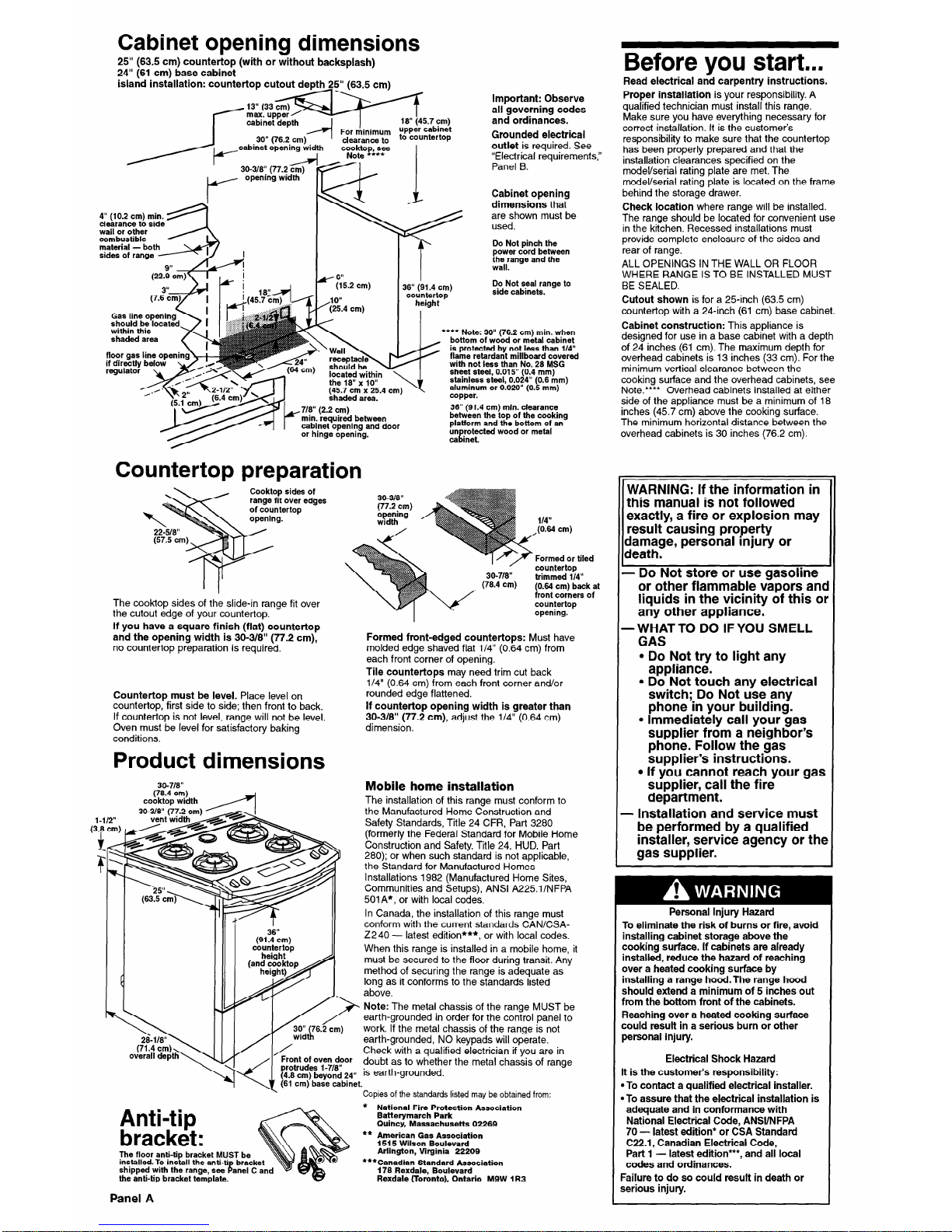
Cabinet opening dimensions
25” (63.5 cm) countertop (with or without backsplash)
24” (61 cm) base cabinet
island installation: countertop cutout depth 25” (63.5 cm)
Before you start...
Read electrical and carpentry instructions.
Proper installation
is your responsibility. A
qualified technician must install this range.
Make sure you have everything necessary for
correct installation. It is the customer’s
responsibility to make sure that the countertop
has been properly prepared and that the
installation clearances specified on the
model/serial rating plate are met. The
model/serial rating plate is located on the frame
behind the storage drawer.
Check location
where range will be installed.
The range should be located for convenient use
in the kitchen. Recessed installations must
provide complete enclosure of the sides and
rear of range.
ALL OPENINGS IN THE WALL OR FLOOR
WHERE RANGE IS TO BE INSTALLED MUST
BE SEALED.
Cutout shown
is for a 25-inch (63.5 cm)
countertop with a 24-inch (61 cm) base cabinet.
Cabinet construction:
This appliance is
designed for use in a base cabinet with a depth
of 24 inches (61 cm). The maximum depth for
overhead cabinets is 13 inches (33 cm). For the
minimum vertical clearance between the
cooking surface and the overhead cabinets, see
Note.‘*** Overhead cabinets installed at either
side of the appliance must be a minimum of 18
inches (45.7 cm) above the cooking surface.
The minimum horizontal distance between the
overhead cabinets is 30 inches (76.2 cm).
Important: Observe
all governing codes
and ordinances.
Grounded electrical
outlet
is required. See
“Electrical requirements,”
Panel B.
30-3/8” (77.2 cm)
r
opening width
1
cookto see
P,
Note ***
Cabinet opening
dimensions
that
are shown must be
used.
Do Not pinch the
power cord between
the range and the
wall.
4” (10.2 cm) min.
4
clearance to side
wall or other
combustible
material - bot
y &i.2 cm)
,lO”
(25.4 cm)
I
min. required between
cabinet opening and door
or hinge opening.
Do Not seal range to
side cabinets.
36” (91.4 cm)
countertop
height
**** Note: 30” (76.2 cm) min. when
bottom of wood or metal cabinet
is protected by not less than 114”
flame retardant milfboard covered
with not less than No. 28 MSG
sheet steel, 0.015” (0.4 mm)
stainless steel, 0.024” (0.6 mm)
aluminum or 0.020” (0.5 mm)
copper.
36” (91.4 cm) min. clearance
between the top of the cooking
platform and the bottom of an
un rotected wood or metal
1. ca met.
Countertop preparation
WARNING: If the information in
this manual is not followed
exactly, a fire or explosion may
result causing property
damage, personal injury or
death.
- Do Not store or use gasoline
or other flammable vapors and
liquids in the vicinity of this or
any other appliance.
-WHAT TO DO IF YOU SMELL
GAS
l
Do Not try to light any
appliance.
l
Do Not touch any electrical
switch; Do Not use any
phone in your building.
l
Immediately call your gas
supplier from a neighbor’s
phone. Follow the gas
supplier’s instructions.
l
If you cannot reach your gas
supplier, call the fire
department.
- Installation and service must
be performed by a qualified
installer, service agency or the
gas supplier.
Personal Injury Hazard
To eliminate the risk of burns or fire, avoid
installing cabinet storage above the
cooking surface. If cabinets are already
installed, reduce the hazard of reaching
over a heated cooking surface by
installing a range hood.The range hood
should extend a minimum of 5 inches out
from the bottom front of the cabinets.
Reaching over a heated cooking surface
could result in a serious burn or other
personal injury.
Electrical Shock Hazard
It is the customer’s responsibility:
*To contact a qualified electrical installer.
*To assure that the electrical installation is
adequate and in conformance with
National Electrical Code, ANWNFPA
70 - latest edition* or CSA Standard
C22.1, Canadian Electrical Code,
Part 1
- latest edition”*, and all local
codes and ordinances.
Failure to do so could result in death or
serious injury.
ides of
ver edges
top
The cooktop sides of the slide-in range fit over
the cutout edge of your countertop.
If you have a square finish (flat) countertop
and the opening width is 30-3/a” (77.2 cm),
no countertop preparation is required.
30-3/8”
(77.2 cm)
;ydet”h’ng /
ormed or tiled
30-7&I”
(78.4 cm)
countertop
trimmed l/4”
(0.64 cm) back at
front corners of
countertop
-1 ’
opening.
Formed front-edged countertops:
Must have
molded edge shaved flat l/4” (0.64 cm) from
each front corner of opening.
Tile countertops
may need trim cut back
l/4” (0.64 cm) from each front corner and/or
rounded edge flattened.
If countertop opening width is greater than
30-3/8” (77.2
cm),
adjust the l/4” (0.64 cm)
dimension.
Countertop must
be
level.
Place level on
countertop, first side to side; then front to back.
If countertop is not level, range will not be level.
Oven must be level for satisfactory baking
conditions.
Product dimensions
Mobile home installation
The installation of this range must conform to
the Manufactured Home Construction and
Safety Standards, Title 24 CFR, Part 3280
(formerly the Federal Standard for Mobile Home
Construction and Safety, Title 24, HUD, Part
280); or when such standard is not applicable,
the Standard for Manufactured Homes
Installations 1982 (Manufactured Home Sites,
Communities and Setups), ANSI A225.1INFPA
501A*, or with local codes.
In Canada, the installation of this ranae must
conform with the current standards CAN/CSA2240 - latest edition***, or with local codes.
When this range is installed in a mobile home, it
must be secured to the floor during transit. Any
method of securing the range is adequate as
long as it conforms to the standards listed
30-718”
(78.4 cm)
cooktop width
Fr /A- above.
Note:
The
metal chassis of the range MUST be
earth-grounded in order for the con&o1 panel to
work. If the metal chassis of the range is not
earth-grounded, NO keypads will operate.
Check with a qualified electrician if you are in
.
;;-~u~$l~;,rJ~Or
doubt as to whether the metal chassis of range
(4-s cm) beyond
24”
is earth-grounded.
(61 cm) base cabinet.
Copies of the standards listed may be obtained from:
* National Fire Protection Association
Batterymarch Park
Quincy, Massachusetts 02269
** American Gas Association
1515 Wilson Boulevard
Arlington, Virginia 22209
***Canadian Standard Association
176 Rexdale, Boulevard
Rexdale (Toronto), Ontario M9W 1 R3
Anti-tip
bracket:
The floor anti-tip bracket MUST be
installed. To install the anti-ti
shipped with the range, see
F
bracket
anel C and
the anti-tip bracket template.
Panel
A
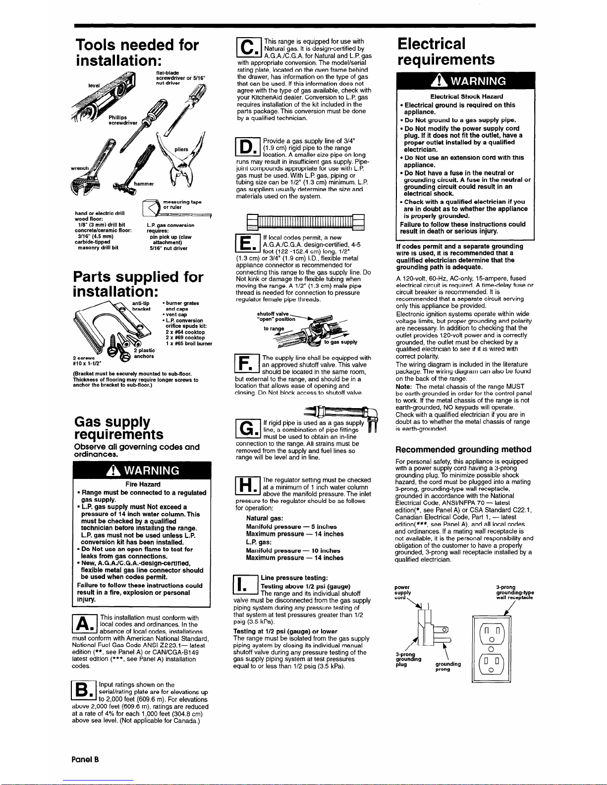
Tools needed for
installation:
flat-blade
screwdriver or 5/l 6”
hand or electric drill
wood floor:
l/S” (3 mm) drill bit
concrete/ceramic floor:
3/16” (4.5 mm)
carbide-tipped
masonry drill bit
L.P. gas conversion
requires:
pin pick up (claw
attachment)
5/16” nut driver
Parts
supplied for
installation:
L 2-plastic
anchors
l
burner grates
and caps
l
vent cap
l
L.P. conversion
orifice spuds kit:
2 x #64 cooktop
2 x #69 cooktop
1 x #65 broil burner
(Bracket must be securely mounted to sub-floor.
Thickness of flooring may require longer screws to
anchor the bracket to sub-floor.)
Gas supply
requirements
Observe all governing codes and
ordinances.
Fire Hazard
l
Range must be connected to a regulated
gas supply.
l
L.P. gas supply must Not exceed a
pressure of 14 inch water column. This
must be checked by a qualified
technician before installing the range.
L.P. gas must not be used unless L.P.
conversion kit has been installed.
l
Do Not use an open flame to test for
leaks from gas connections.
l
New, A.G.AJC.G.A.-design-certified,
flexible metal gas line connector should
be used when codes permit.
Failure to follow these instructions could
result in a fire, explosion or personal
injury.
IA
This installation must conform with
local codes and ordinances. In the
. absence of local codes installations
must conform with American National Standard,
National Fuel Gas Code ANSI Z223.1- latest
edition (**,
see Panel A) or CAN/CGA-B1 49
latest edition (***,
see Panel A) installation
codes.
le
Input ratings shown on the
. serial/rating plate are for elevations up
to 2,000 feet (609.6 m). For elevations
above 2,000 feet (609.6 m), ratings are reduced
at a rate of 4% for each 1,000 feet (304.8 cm)
above sea level. (Not applicable for Canada.)
El
This range is equipped for use with
n
Natural gas. It is design-certified by
A.G.A./C.G.A. for Natural and L.P. gas
with appropriate conversion. The model/serial
rating plate, located on the oven frame behind
the drawer, has information on the type of gas
that can be used. If this information does not
agree with the type of gas available, check with
your KitchenAid dealer. Conversion to L.P. gas
requires installation of the kit included in the
parts package. This conversion must be done
by a qualified technician.
ID.I
Provide a gas supply line of 3/4”
(1.9 cm) rigid pipe to the range
location. A smaller size pipe on long
runs may result in insufficient gas supply. Pipe-
joint compounds appropriate for use with L.P.
gas must be used. With L.P. gas, piping or
tubing size can be l/2” (1.3 cm) minimum. L.P.
gas suppliers usually determine the size and
materials used on the system.
El
If local codes permit, a new
A.G.A./C.G.A. design-certified, 4-5
foot (122 -152.4 cm) long. l/2”
(1.3 cm) or 3/4” (1.9 cm) I.D.,‘flexible metal
appliance connector is recommended for
connecting this range to the gas supply line. Do
Not kink or damage the flexible tubing when
moving the range. A l/2” (1.3 cm) male pipe
thread is needed for connection to pressure
regulator female pipe threads.
El
The supply line shall be equipped with
an approved shutoff valve. This valve
should be located in the same room.
but external to the range, and should be in a ’
location that allows ease of opening and
closing. Do Not block access to shutoff valve.
El
If rigid pipe is used
line, a combination of pipe fittings
must be used to obtain an in-line
connection to the range. All strains must be
removed from the supply and fuel lines so
range will be level and in line.
IH
The regulator setting must be checked
n
at a minimum of 1 inch water column
above the manifold oressure. The inlet
pressure to the regulator should be as follows
for operation:
Natural gas:
Manifold pressure - 5 inches
Maximum pressure - 14 inches
L.P. gas:
Manifold pressure - 10 inches
Maximum pressure - 14 inches
(1.
Line pressure testing:
Testing above l/2 psi (gauge)
The range and its individual shutoff
valve must be disconnected from the gas supply
piping system during any pressure testing of
that system at test pressures greater than l/2
psig (3.5 kPa).
Testing at l/2 psi (gauge) or lower
The range must be isolated from the gas supply
piping system by closing its individual manual
shutoff valve during any pressure testing of the
gas supply piping system at test pressures
equal to or less than l/2 psig (3.5 kPa).
Electrical
requirements
Electrical Shock Hazard
l
Electrical ground is required on this
appliance.
l
Do Not ground to a gas supply pipe.
l
Do Not modify the power supply cord
plug. If it does not fit the outlet, have a
proper outlet installed by a qualified
electrician.
. Do Not use an extension cord with this
appliance.
l
Do Not have a fuse in the neutral or
grounding circuit. A fuse in the neutral or
grounding circuit could result in an
electrical shock.
l
Check with a qualified electrician if you
are in doubt as to whether the appliance
is properly grounded.
Failure to follow these instructions could
result in death or serious injury.
If codes permit and a separate grounding
wire is used, it is recommended that a
qualified electrician determine that the
grounding path is adequate.
A 120-volt, 60-Hz, AC-only, 15-ampere, fused
electrical circuit is required. A time-delay fuse or
circuit breaker is recommended. It is
recommended that a separate circuit serving
only this appliance be provided.
Electronic ignition systems operate within wide
voltage limits, but proper grounding and polarity
are necessary. In addition to checking that the
outlet provides 120-volt power and is correctly
grounded, the outlet must be checked by a
qualified electrician to see if it is wired with
correct polarity.
The wiring diagram is included in the literature
package. The wiring diagram can also be found
on the back of the range.
Note:
The metal chassis of the range MUST
be earth-grounded in order for the control panel
to work. If the metal chassis of the range is not
earth-grounded, NO keypads will operate.
Check with a qualified electrician if you are in
doubt as to whether the metal chassis of range
is earth-grounded.
Recommended grounding method
For personal safety, this appliance is equipped
with a power supply cord having a 3-prong
grounding plug. To minimize possible shock
hazard, the cord must be plugged into a mating
3-prong, grounding-type wall receptacle,
grounded in accordance with the National
Electrical Code, ANSVNFPA 70 - latest
edition(*, see Panel A) or CSA Standard C22.1,
Canadian Electrical Code, Part 1, - latest
edition( ***, see Panel A), and all local codes
and ordinances. If a mating wall receptacle is
not available, it is the personal responsibility and
obligation of the customer to have a properly
grounded, 3-prong wall receptacle installed by a
qualified electrician.
power
plug
grounding
prong
3-prong
grounding-type
wall receptacle
J
Panel B
 Loading...