

Page 1
INSTALLATION INSTRUCTIONS
18" Icemaker Trim Kit Accessory
In many instances, customers want to integrate the icemaker within overall kitchen design by installing panels matching the
cabinets. After panel is cut and finished as described below, use the materials in this accessory kit to install the custom panel
by following the installation instructions.
Trim Kit Contains:
1 Handle - Trim
1 Handle Assembly
1 Door Trim - L.S.
1 Door Trim - R.S.
1 Door Trim - Bottom
2 Lower Panel Trims
1 Lower Panel Trim - L.S.
1 Lower Panel Trim - R.S.
3 Handle Mounting Screws - #8-18 x 3/4" Low
Round Head
19 Trim Mounting Screws - #6-20 x 3/8" Flat Head
2 Door Springs
2 Door Spring Dampeners
1 Anti-T ip Bracket
Tools Required:
7/64" Drill Bit
Power Drill
Center Punch
Fine Point Marker
Masking Tape
Phillips Screwdriver
Hammer
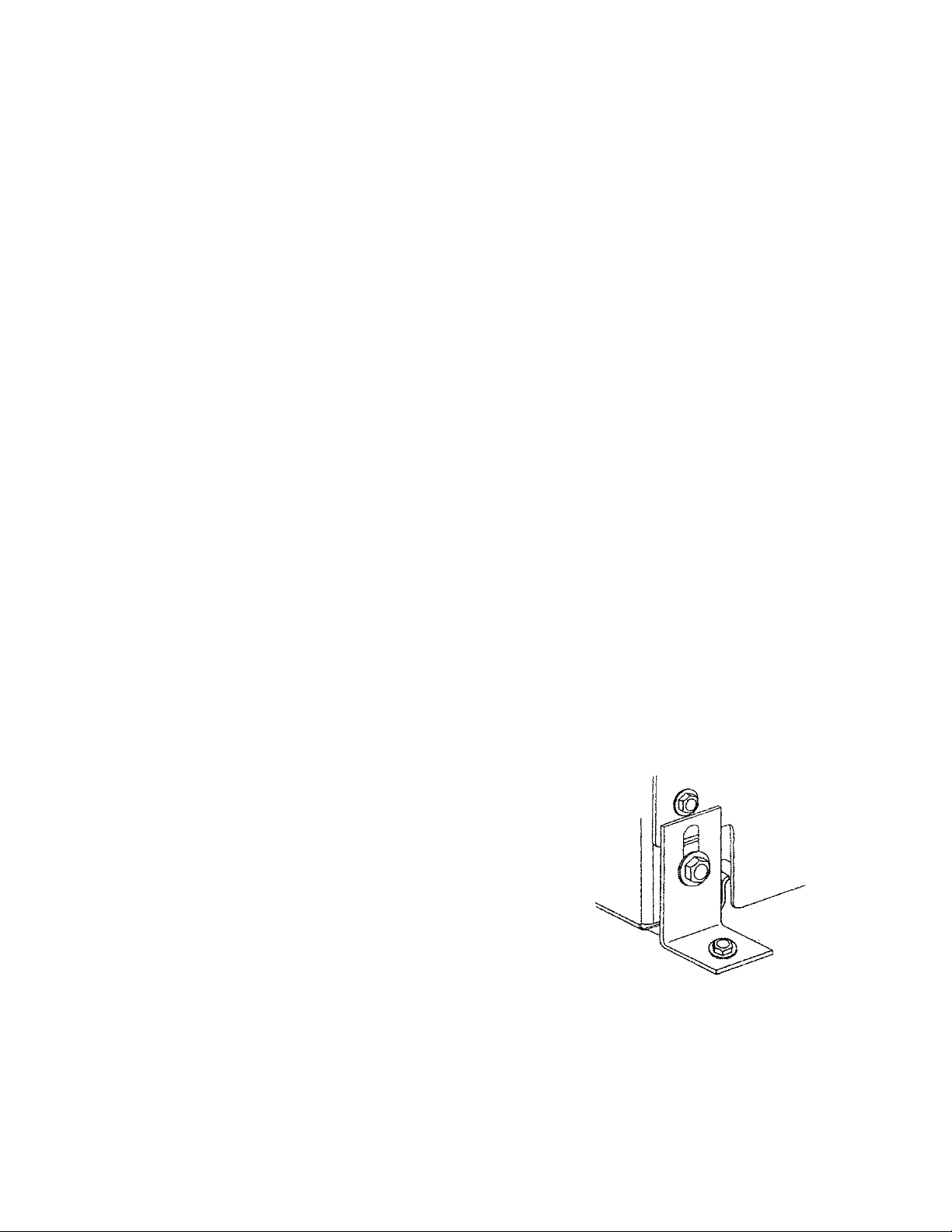
Anti-tip Bracket Installation for
Freestanding Installation
The icemaker may tip forward when the door is fully opened
if you apply weight to the top edge of the door. The anti-tip
bracket must be used if the icemaker does not have a
securely mounted countertop or cabinets installed
directly above it. The anti-tip bracket can be placed on
either the left or right back of the icemaker.
1. Adjust the height of the icemaker if necessary. Follow the
instructions in the “Leveling the Icemaker” section of the
Use and Care Guide.
2. Decide whether you want to install the anti-tip bracket on
the left or right back of the icemaker.
NOTE: You will need enough room behind the icemaker
to anchor the bracket securely to the floor. Make sure the
drain from the icemaker aligns with the floor drain you’ve
installed.
3. Using a 5/16" wrench, remove the hex washer head
screw from the bottom back of the icemaker (left or right
side as determined in Step 2).
4. Attach the anti-tip bracket, as shown, but do not tighten
the screw completely.
Before Y ou Begin:
A qualified service technician must perform installation.
Cutting Notes
1. Match woodgrain direction with that of adjacent cabinets.
IMPORTANT: Use moisture resistant sealer on both sides
and all edges of wood panels to protect from humidity.
Icemaker is subject to humidity.
© Whirlpool Corporation 2001
(All Rights Reserved)
5. Adjust the anti-tip bracket so that it rests securely on the
floor. TIGHTEN THE SCREW COMPLETELY.
6. Carefully place the icemaker in its final location.
7. Anchor the anti-tip bracket securely to the floor using
hardware appropriate to the type of flooring.
(continued)
Instruction Sheet 8171726 Rev. B 3/01
1
Page 2
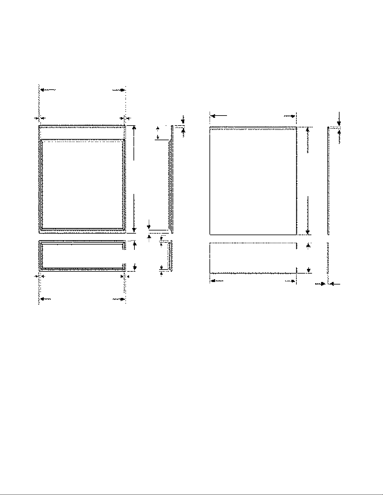
CUSTOM PANEL DIAGRAM
Custom Panel Dimensions
• Requires the edge to be 1/4" (6.35mm) thickness.
• Customer can use 3/4" (19.05mm) or 1/4" (6.35mm) thick
custom panels.
Please review illustrations below to make panels fit
correctly.
17 1/2" max. (444mm)
17 3/8" min. (442mm)
Notch 1/16"
9/32" (7mm)
9/32" (7mm)
2 61/64"
(75mm)
21 13/16" max.
(554mm)
21 11/16" min.
(551mm)
(1.5mm) deep
15/32"
(12mm)
17 1/2" max. (444mm)
17 3/8" min. (442mm)
Notch 1/16"
(1.5mm) deep
15/32"
(12mm)
21 13/16"
max.
(554mm)
21 11/16"
min.
(551mm)
9/16"
(14.30mm)
9/32" (7mm)
6 3/16" max. (157mm)
6 1/16" min. (154mm)
9/32" (7mm)9/32" (7mm)
17 1/2" max. (444mm)
17 3/8" min. (442mm)
9/32" (7mm)
Custom 3/4" thick panel
Installation Procedure
Follow steps below:
1. Choose your custom panel design and cut to the
dimensions as noted in custom panel diagram section.
2. Remove KitchenAid nameplate from ice compartment
door.
3. Remove lower panel and set aside.
4. Remove old door springs and discard. New door springs
supplied in kit.
5. Slip vinyl spring dampeners, supplied, over new springs.
6. Install new springs with dampeners and install on ice
compartment door.
7. Remove old handle assembly from ice compartment
door by removing (3) screws. Discard.
IMPORTANT: When handle is removed, the door
will fall and must be held in place temporarily by
holding in place or taping the door to the cabinet.
8171726-B
6 3/16" max. (157mm)
6 1/16" min. (154mm)
17 1/2" max. (444mm)
17 3/8" min. (442mm)
1/4" Panel
8. Install new handle assembly and handle trim using
(3) #8-18 x 3/4" screws supplied in kit. See trim
installation diagram.
9. Assemble trim to ice compartment door using masking
tape. Make sure all the trim pieces line up correctly.
Adjust trim as required before drilling. You will use the
trim as a template to drill holes. See trim installation
diagram for trim location.
10. Next, assemble the trim pieces to the lower panel
using masking tape. Make sure all of the trim pieces
line up correctly. NOTE: Sometimes the lower panel
plastic frame may require squeezing together to make
the trim fit correctly before drilling holes. You will
use the trim as a template to drill holes. See trim
installation diagram for trim location.
2
1/4"
(6.35mm)
(continued)
Page 3

11. Make sure all of the trim pieces are lined up correctly.
Now mark your holes with a fine tip marker.
12. Using the center punch, tap the punch at each mark to
assist drilling.
13. Drill nineteen (19) holes using a 7/64" diameter drill bit.
14. Install all the trim on the ice compartment door except
the right side using #6-20 x 3/8" flat head screws. You
want to leave the right side trim off to slide in your
custom panel.
Trim Installation Diagram
15. Install all the trim on the lower panel except the right
side using #6-20 x 3/8" flat head screws. You want to
leave the right side trim off to slide in your custom
panel.
16. Slide in your custom panels and complete installation
of the right side trim on the ice compartment door and
lower panel.
17. Install lower panel.
Handle trim
Handle assembly
Door trim, L.S.
Ice compartment door
Lower panel
trim, L.S.
Door bottom trim
Lower panel
Door trim, R.S.
Lower panel trim, R.S.
Lower panel trim, TOP
Lower panel trim,
bottom
3
8171726-B
Page 4

INSTRUCTIONS D’INSTALLATION
Trousse de garnitures pour
les machines à glaçons de 18 pouces
Dans bien des cas, les clients veulent intégrer leur machine à glaçons avec la conception générale de leur cuisine en posant
des panneaux s’assortissant aux armoires. Après avoir coupé et fini le panneau comme il est indiqué ci-dessous, utiliser les
matériaux livrés dans la trousse pour poser le panneau personnalisé conformément aux instructions d’installation qui suivent.
La trousse de garnitures contient :
1 garniture de poignée
1 poignée
1 garniture de porte - gauche
1 garniture de porte - droite
1 garniture de porte - inférieure
2 garnitures de panneau inférieur
1 garniture de panneau inférieur - gauche
1 garniture de panneau inférieur - droite
3 vis de fixation de poignée - n° 8-18 x 3/4 de pouce
à tête ronde basse
19 vis de fixation pour les garnitures -
n° 6-20 x 3/8 de pouce à tête plate
2 ressorts de porte
2 amortisseurs de ressort de porte
1 support antibasculement
Outils requis :
Un foret de 7/64 de pouce
Une perceuse
Un pointeau
Un marqueur à pointe fine
Un ruban à mesurer
Un tournevis à empreinte cruciforme (Phillips)
Un marteau
Avant de commencer :
Un technicien qualifié doit procéder à cette installation.
Notes concernant la coupe
1. Faire correspondre le sens du grain du bois avec celui
des armoires adjacentes.
Installation du support
antibasculement sur les machines à
glaçons autoportantes
La machine à glaçons peut basculer vers l’avant si, pendant
que la porte est complètement ouverte, un poids est
appliqué sur le bord supérieur de la porte. Le support
antibasculement doit être utilisé si un dessus de
comptoir ou si des armoires ne sont pas directement
installés et montés en toute sécurité au-dessus de la
machine à glaçons. Le support antibasculement peut être
posé à l’arrière gauche ou à l’arrière droit de la machine à
glaçons.
1. Au besoin, régler la hauteur de la machine à glaçons.
Suivre les instructions figurant dans la section «Mise de
niveau de la machine à glaçons» stipulées dans le Guide
d’utilisation et d’entretien.
2. Décider si l’on veut poser le support antibasculement à
l’arrière gauche ou à l’arrière droit de la machine à glaçons.
NOTA : Il devra y avoir suffisamment d’espace derrière
la machine à glaçons pour ancrer en toute sécurité le
support sur le plancher. S’assurer que le rejet à l’égout
de la machine à glaçons s’aligne avec le rejet à l’égout
du plancher que l’on a installé.
3. À l’aide d’une clé de 5/16 de pouce, déposer la vis à tête
hexagonale et à rondelle imperdable de la partie arrière
inférieure de la machine à glaçons (côté gauche ou droit,
selon ce que l’on a déterminé lors de l’opération 2.).
4. Attacher le support antibasculement comme il est illustré,
mais ne pas serrer complètement la vis.
IMPORTANT : Appliquer un bouche-pores résistant à
l’humidité sur les deux côtés et sur tous les bords des
panneaux en bois pour les protéger de l’humidité. La
machine à glaçons est soumise à l’humidité.
© Whirlpool Corporation, 2001
(Tous droits réservés)
5. Régler le support antibasculement de façon qu’il repose
en toute sécurité sur le plancher. SERRER MAINTENANT
COMPLÈTEMENT LA VIS.
6. Prudemment, mettre la machine à glaçons dans sa
position finale.
7. Ancrer en toute sécurité le support antibasculement au
plancher en utilisant les fixations appropriées en fonction
du type de plancher.
(suite)
Feuille d’instructions 8171726 Rév. B 3/01
1
Page 5

SCHÉMA DU PANNEAU PERSONNALISÉ
Dimensions du panneau personnalisé
• Son bord devra avoir une épaisseur de 1/4 de pouce
(6,35 mm).
• Le client peut utiliser des panneaux personnalisés de
3/4 de pouce (19,05 mm) ou de 1/4 de pouce (6,35 mm)
d’épaisseur.
Étudier attentivement les illustrations ci-dessous afin de
s’assurer que les panneaux s’ajustent correctement.
17 1/2 pouces max.
(444 mm)
17 3/8 pouces min.
(442 mm)
9/32 de pouce
(7 mm )
9/32 de pouce
(7 mm)
Encoche 1/16 de
pouce (1,5 mm)
de profondeur
17 1/2 pouces max.
(444 mm)
17 3/8
pouces min.
(442 mm)
Encoche 1/16 de
pouce (1,5 mm)
de profondeur
2 61/64
pouces
(75 mm)
21 13/16 pouces
max. (554 mm)
21 11/16 pouces
min. (551 mm)
9/16 de
pouce
(14,30 mm)
6 3/16 pouces max. (157 mm)
6 1/16 pouces min. (154 mm)
9/32 de pouce (7 mm)
17 1/2 pouces max. (444 mm)
17 3/8 pouces min. (442 mm)
9/32 de
pouce (7 mm)
Panneau personnalisé de 3/4 de pouce
d’épaisseur
Méthode d’installation
15/32 de
pouce
(12 mm)
9/32
de pouce
(7 mm)
21 13/16
pouces
max.
(554 mm)
21 11/16
pouces
min.
(551 mm)
6 3/16 pouces max. (157 mm)
6 1/16 pouces min. (154 mm)
17 1/2 pouces max. (444 mm)
17 3/8 pouces min. (442 mm)
Panneau de 1/4 de pouce
15/32
de
pouce
(12 mm)
1/4 de
pouce
(6,35 mm)
Procéder comme il est indiqué ci-dessous :
1. Choisir le panneau personnalisé que l’on désire poser et
le couper aux dimensions indiquées dans la section
«Schéma du panneau personnalisé».
2. Déposer la plaque KitchenAid de la porte du compartiment
à glaçons.
3. Déposer le panneau inférieur et le mettre de côté.
4. Déposer les anciens ressorts de la porte et les jeter. Des
ressorts de porte neufs sont fournis avec la trousse.
5. Glisser les amortisseurs de ressort en vinyle fournis
par-dessus les ressorts neufs.
6. Poser les ressorts neufs et les amortisseurs, puis reposer
la porte du compartiment à glaçons.
7. Déposer l’ancienne poignée de la porte du compartiment à
glaçons en déposant les trois (3) vis; jeter les vis.
IMPORTANT : Dès que la poignée est déposée, la porte
tombera et elle devra être retenue temporairement en
place, soit en la tenant, soit en la faisant tenir avec du
ruban sur la carrosserie.
8171726-B
8. Poser la poignée neuve et sa garniture à l’aide de
trois (3) vis n° 8-18 x 3/4 de pouce livrées dans la trousse. Se reporter au schéma d’installation de la garniture.
9. À l’aide de ruban-cache, assembler la garniture sur la
porte du compartiment à glaçons. S’assurer que tous
les morceaux de la garniture s’alignent bien. Avant de
percer , ajuster, au besoin, la garniture. La garniture
servira de gabarit pour percer les trous. Se reporter au
schéma d’installation de la garniture pour connaître
l’emplacement de la garniture.
10. Ensuite, à l’aide de ruban-cache, assembler les
morceaux de la garniture sur le panneau inférieur.
S’assurer que tous les morceaux de la garniture
s’alignent bien. NOTA : Il faudra parfois serrer le cadre
en plastique du panneau inférieur pour que la garniture
s’ajuste correctement avant de percer les trous. La
garniture servira de gabarit pour percer les trous. Se
reporter au schéma d’installation de la garniture.
(suite)
2
Page 6

11. S’assurer que tous les morceaux de la garniture
s’alignent bien. Maintenant, repérer les trous avec un
marqueur à pointe fine.
12. À l’aide d’un pointeau, amorcer les trous à chaque repère
fait avec le marqueur afin de faciliter le perçage.
13. À l’aide d’un foret de 7/64 de pouce de diamètre, percer
dix-neuf (19) trous.
14.
À l’aide des vis à tête plate n° 6-20 x 3/8 de pouce, installer toutes les garnitures sur la porte du compartiment à
glaçons, à l’exception du côté droit. La garniture du côté
droit ne doit pas être posée pour le moment afin de
pouvoir glisser en place le panneau personnalisé.
Schéma d’installation des garnitures
15. À l’aide des vis à tête plate n° 6-20 x 3/8 de pouce,
installer toutes les garnitures sur le panneau inférieur, à
l’exception du côté droit. La garniture du côté droit ne doit
pas être posée pour le moment afin de pouvoir glisser en
place le panneau personnalisé.
16. Glisser le panneau personnalisé en place et terminer
l’installation de la garniture sur le côté droit et sur le
panneau inférieur.
17. Poser le panneau inférieur.
Garniture de poignée
Poignée
Garniture de
porte - gauche
Porte du compartiment
à glaçons
Garniture
de panneau
inférieur - gauche
Garniture
inférieure
de porte
Panneau inférieur
Garniture de porte - droite
Garniture de panneau
inférieur - droite
Garniture supérieure
du panneau inférieur
Garniture inférieure
du panneau inférieur
3
8171726-B
 Loading...