

KitchenAid 24"" (61 cm) Warming Drawer, 27"" (68.6 cm) Warming Drawer, 30"" (76.2 cm) Warming Drawer Installation Instructions Manual

INSTALLATION INSTRUCTIONS
IMPORTANT:
Save for local electrical inspector's use.
IMPORTANT :
À conserver pour consultation par l'inspecteur local des installations électriques.
W10600304A
24" (61 CM), 27" (68.6 CM), AND 30" (76.2 CM)
INDOOR/OUTDOOR ELECTRIC WARMING DRAWER
INSTRUCTIONS D'INSTALLATION
TIROIR-RÉCHAUD ÉLECTRIQUE POUR USAGE
INTÉRIEUR/EXTÉRIEUR DE
24" (61 CM), 27" (68,6 CM), ET 30" (76,2 CM)
Table of Contents/Table des matières
WARMING DRAWER SAFETY ......................................................2
INSTALLATION REQUIREMENTS................................................3
Tools and Parts ............................................................................3
Location Requirements................................................................3
Electrical Requirements ...............................................................4
INSTALLATION INSTRUCTIONS..................................................5
Install Warming Drawer................................................................5
Complete Installation ...................................................................5
CUSTOM DRAWER FRONT INSTALLATION
INSTRUCTIONS FOR WARMING DRAWERS..............................6
Tools and Parts ............................................................................6
Install Custom Drawer Front Panel ..............................................6
SÉCURITÉ DU TIROIR-RÉCHAUD ...............................................7
EXIGENCES D'INSTALLATION.....................................................8
Outillage et pièces........................................................................8
Exigences d'emplacement...........................................................8
Spécifications électriques ............................................................9
INSTRUCTIONS D'INSTALLATION.............................................10
Installation du tiroir-réchaud ......................................................10
Achever l'installation ..................................................................10
INSTRUCTIONS D'INSTALLATION DE LA FAÇADE DU
TIROIR PERSONNALISÉ POUR TIROIR-RÉCHAUD ................11
Outillage et pièces......................................................................11
Installation du panneau de la façade du tiroir personnalisé......11
WARMING DRAWER SAFETY
You can be killed or seriously injured if you don't immediately
You
can be killed or seriously injured if you don't
follow
All safety messages will tell you what the potential hazard is, tell you how to reduce the chance of injury, and tell you what can
happen if the instructions are not followed.
Your safety and the safety of others are very important.
We have provided many important safety messages in this manual and on your appliance. Always read and obey all safety
messages.
This is the safety alert symbol.
This symbol alerts you to potential hazards that can kill or hurt you and others.
All safety messages will follow the safety alert symbol and either the word “DANGER” or “WARNING.”
These words mean:
follow instructions.
instructions.
DANGER
WARNING
2
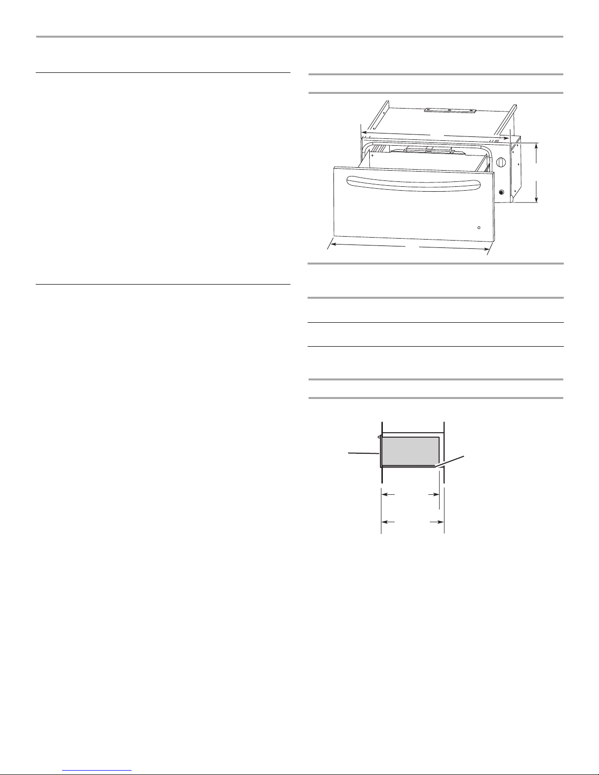
INSTALLATION REQUIREMENTS
A
B
C
Warming
drawer
front
Support surface must be
solid, level, flush with
bottom of cabinet cutout.
22³⁄₄"
(57.8 cm)
recessed
oven depth
24"
(61 cm)
min. cutout
depth
Tools and Parts
Gather the required tools and parts before starting installation.
Read and follow the instructions provided with any tools listed
here.
Tools needed
■ Phillips screwdriver
■ Drill
■ 1³⁄₈" (3.5 cm) hole saw
Parts supplied
■ 4 - #8-18 x ⁵⁄₈" screws
■ Lens (for panel ready models)
Check local codes. Check existing electrical supply. See
“Electrical Requirements.”
It is recommended that all electrical connections be made by a
licensed, qualified electrical installer.
Location Requirements
IMPORTANT: Observe all governing codes and ordinances.
■ Cutout dimensions that are shown must be used. Given
dimensions provide minimum clearance with warming drawer.
■ Recessed installation area must provide complete enclosure
around the recessed portion of the warming drawer.
■ Grounded electrical supply is required. See “Electrical
Requirements” section.
■ Electrical supply outlet should be located in the rear wall on
the upper right-hand side of the cutout or in an adjacent
cabinet. The outlet must be recessed. If the electrical outlet is
located in an adjacent cabinet, a 1³⁄₈" (3.5 cm) minimum
diameter hole should have been drilled in the back of the
cutout or support surface to pass the power supply cord
through to the outlet.
■ Warming drawer support surface must be solid, level and
flush with bottom of cabinet cutout.
■ Warming drawers with oiled bronze, black glass, and white
glass panels are approved for indoor use only.
For best performance results, make sure the warming drawer is
leveled before completing installation. There is no way to level the
warming drawer after it has been installed. If the installation is not
level, the door may slide open or not seal tightly, allowing heat to
escape.
NOTE: If installing the warming drawer below another product,
refer to that product’s literature for any installation requirements.
Product Dimensions
WARMING
DRAWER
SIZE
24"
(61 cm)
27"
(68.6 cm)
30"
(76.2 cm)
OVERALL
WIDTH (A)
23³⁄₄"
(60.3 cm)
26³⁄₄"
(67.9 cm)
29³⁄₄"
(75.6 cm)
Cabinet Dimensions
Cabinet Side View
RECESSED
WIDTH (B)
22¹⁄₄"
(56.5 cm)
25¹⁄₄"
(64.1 cm)
28¹⁄₄"
(71.8 cm)
RECESSED
HEIGHT (C)
9"
(22.9 cm)
9"
(22.9 cm)
9"
(22.9 cm)
3
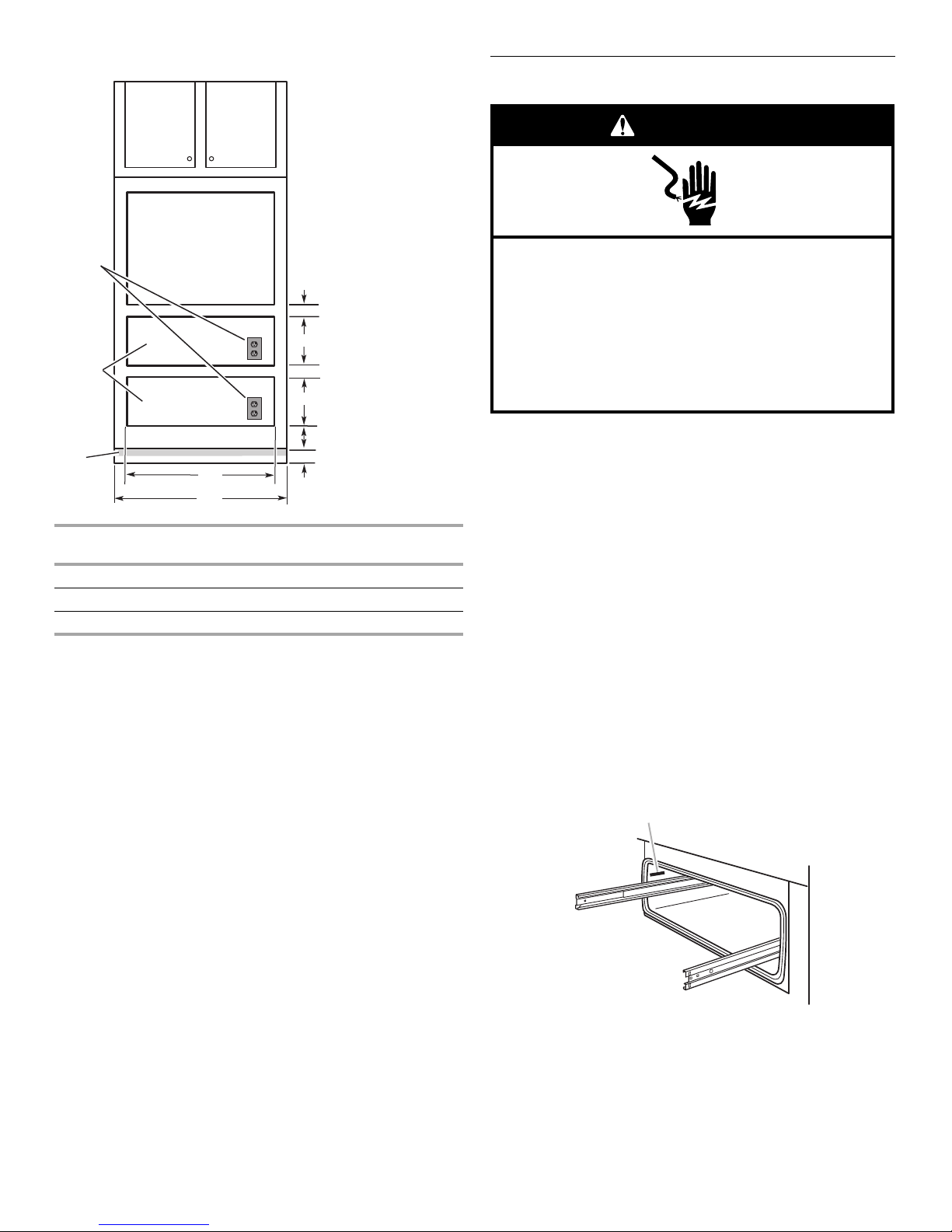
Cabinet Front View
2¹/₂" (6.4 cm) min.
2¹/₂" (6.4 cm) min.
9¹/₈" (23.2 cm)
4" (10.2 cm)
B
Recommended 4¹/₄" (10.8 cm)
Minimum 1" (2.5 cm)
A
9¹/₈" (23.2 cm)
Toe
kick
Warming
drawer
cutouts
120 volt
grounded
outlet
(or located
in adjacent
cabinet)
Electrical Shock Hazard
Plug into a grounded 3 prong outlet.
Do not remove ground prong.
Do not use an adapter.
Do not use an extension cord.
Failure to follow these instructions can result in death,
fire, or electrical shock.
WARNING
A
WARMING
DRAWER SIZE
CUTOUT
WIDTH (A)
MIN. CABINET
WIDTH (B)
24" (61 cm) 22¹⁄₂" (57.1 cm) 24" (61 cm)
27" (68.6 cm) 25¹⁄₂" (64.8 cm) 27" (68.6 cm)
30" (76.2 cm) 28¹⁄₂" (72.4 cm) 30" (76.2 cm)
Warming drawer can be installed as an indoor single or double
installation or installed under a single oven. Two warming drawers
under a single oven are shown.
NOTE: The warming drawer cannot be leveled after being
installed.
For outdoor installation, follow the cutout dimensions above.
Install the outdoor warming drawer in a permanent fixture.
Custom Wood Drawer Front
If you plan to install a custom wood panel to match your
cabinets, we recommend consulting a qualified cabinetmaker or
carpenter. The back of the wood panel must be sealed to avoid
moisture damage.
Electrical Requirements
IMPORTANT: The warming drawer must be electrically grounded
in accordance with local codes and ordinances, or in the absence
of local codes, with the National Electrical Code, ANSI/NFPA 70
or Canadian Electrical Code, CSA C22.1.
If codes permit and a separate ground wire is used, it is
recommended that a qualified electrical installer determine that
the ground path is adequate.
A copy of the above code standards can be obtained from:
National Fire Protection Association
1 Batterymarch Park
Quincy, MA 02169-7471
CSA International
8501 East Pleasant Valley Road
Cleveland, OH 44131-5575
■ A 120 volt, 60 Hz., AC only, 15-amp fused, electrical circuit is
required. A time-delay fuse or circuit breaker is also
recommended. It is recommended that a separate circuit
serving only this warming drawer be provided.
■ The model/serial rating plate is located above the left-hand
side receiving slide. The warming drawer must be removed to
view the model/serial rating plate. See the following
illustration.
4
A. Model/serial number plate

INSTALLATION INSTRUCTIONS
WARNING
Excessive Weight Hazard
Use two or more people to move and install
warming drawer.
Failure to do so can result in back or other injury.
Electrical Shock Hazard
Plug into a grounded 3 prong outlet.
Do not remove ground prong.
Do not use an adapter.
Do not use an extension cord.
Failure to follow these instructions can result in death,
fire, or electrical shock.
WARNING
A
Install Warming Drawer
1. Turn off power supply. Using 2 or more people, move
warming drawer close to its final location. Remove and
discard shipping materials, tape, and film from the warming
drawer. Remove and set aside racks and other parts from
inside warming drawer.
2. Check that the warming drawer Temperature control knob is
set to the OFF position.
3. Support the warming drawer on a sturdy surface level with
the cutout opening.
6. Open warming drawer and slowly push against the front
panel to slide the drawer completely into the cabinet until the
flanges on the front panel meet the cabinet face.
7. Use the two #8-18 x ⁵⁄₈" screws provided to secure the
warming drawer frame to the cabinet.
A. Two #8-18 x ⁵⁄₈" screws
Complete Installation
1. Check that all parts are now installed. If there is an extra part,
go back through the steps to see which step was skipped.
2. Check that you have all of your tools.
3. Dispose of/recycle all packaging materials.
4. For warming drawer use and cleaning, read the Use and Care
Guide.
5. Turn the Temperature control knob to HI. The light should
illuminate.
4. Plug the power supply cord into the grounded 3 prong outlet.
5. Slide the warming drawer over halfway into the cutout
opening.
If warming drawer(s) does not operate, check the
following:
■ Household fuse is intact and tight; or circuit breaker has not
tripped.
■ Warming drawer is plugged in, and electrical supply is
connected.
If you need Assistance or Service:
Please reference the “Assistance or Service” section of the Use
and Care Guide or contact the dealer from whom you purchased
your warming drawer.
5

CUSTOM DRAWER FRONT INSTALLATION INSTRUCTIONS
A
B
⁵⁄₁₆" (7.9 mm) dia. hole for
indicator light lens (provided
in this kit). Locate lens directly
in front of indicator light.
A
D
D
C
B
E
FOR WARMING DRAWERS
Tools and Parts
Gather the required tools and parts before starting installation.
Read and follow the instructions provided with any tools listed
here.
Tools Needed
■ Phillips screwdriver
■ Drill and appropriate bits
Parts Supplied
■ 6 - #8-18 x ¹⁄₂" screws
■ Indicator light lens
Parts Needed
■ Custom drawer front
■ Custom handle (optional)
■ Adhesive recommended for plastic to wood
Install Custom Drawer Front Panel
The warming drawer has an interface that will allow a modest
range of panel sizes. The actual panel size should be selected by
the customer and the contractor to suit the desired effect. It is
recommended that a qualified carpenter make and install the
custom drawer front and handle(s) to match surrounding
cabinetry.
1. Install warming drawer unit as instructed by the installation
instructions provided with the warming drawer.
2. Create the custom drawer front. Below are the minimum and
maximum dimensions for the custom drawer front. The size
of the custom drawer front for the warming drawer will vary
according to the specific installation. The depth of the panel
will vary in order to have the custom warming drawer flush
with the surrounding cabinets.
3. It is recommended that if a wood or porous custom drawer
front is installed, a high quality spray polyurethane finish be
applied to the inner wood surface.
4. For the lens, drill a ⁵⁄₁₆" (7.9 mm) diameter hole through the
appearance side of the custom drawer front. This hole will
allow the indicator “ON” light to be visible through the custom
drawer front. To secure the lens, use an adhesive specified for
plastic to wood application.
5. Install custom handle (not supplied) through custom drawer
front.
6. The custom drawer front is fastened to the stainless steel
drawer by driving 6 screws through clearance holes in the
drawer front into the wooden or other custom made panel.
A. Optional handle
B. Custom door panel
C. Warming drawer front
D. 6 - #8-18 x ¾" screws
E. Lens
Model A - MAX B - MAX A - MIN B - MIN
24" (61 cm)
Warming Drawer
27" (68.6 cm)
Warming Drawer
30" (76.2 cm)
Warming Drawer
23³⁄₄"
(60.3 cm)
26³⁄₄"
(67.9 cm)
29³⁄₄"
(75.6 cm)
10⁵⁄₁₆"
(26.2 cm)
10⁵⁄₁₆"
(26.2 cm)
10⁵⁄₁₆"
(26.2 cm)
6
23"
(58.4 cm)
26"
(66.1cm)
29"
(73.7cm)
9¹⁄₁₆"
(23.0 cm)
9¹⁄₁₆"
(23.0 cm)
9¹⁄₁₆"
(23.0 cm)

SÉCURITÉ DU TIROIR-RÉCHAUD
Risque possible de décès ou de blessure grave si vous ne
suivez pas immédiatement les instructions.
Risque possible de décès ou de blessure grave si vous
ne suivez pas les instructions.
Tous les messages de sécurité vous diront quel est le danger potentiel et vous disent comment réduire le risque de blessure et
ce qui peut se produire en cas de non-respect des instructions.
Votre sécurité et celle des autres est très importante.
Nous donnons de nombreux messages de sécurité importants dans ce manuel et sur votre appareil ménager. Assurez-vous de
toujours lire tous les messages de sécurité et de vous y conformer.
AVERTISSEMENT
DANGER
Voici le symbole d’alerte de sécurité.
Ce symbole d’alerte de sécurité vous signale les dangers potentiels de décès et de blessures graves à vous
et à d’autres.
Tous les messages de sécurité suivront le symbole d’alerte de sécurité et le mot “DANGER” ou
“AVERTISSEMENT”. Ces mots signifient :
7

EXIGENCES D'INSTALLATION
A
B
C
Façade du
tiroir-réchaud
La surface de support
doit être robuste,
horizontale et en
affleurement avec
le bas de l'ouverture
découpée dans le
placard.
Profondeur
du four
encastré
22³⁄₄" (57,8 cm)
Profondeur min.
de l'ouverture
découpée
24" (61 cm)
Outillage et pièces
Rassembler les outils et pièces nécessaires avant de commencer
l’installation. Lire et suivre les instructions fournies avec les outils
indiqués ici.
Outillage nécessaire
■ Tournevis Phillips
■ Perceuse
■ Scie à guichet de 1³⁄₈" (3,5 cm)
Pièces fournies
■ 4 vis n° 8-18 x ⁵⁄₈"
■ Cabochon (pour les modèles avec panneaux prêts-à-installer)
Consulter les codes locaux. Vérifier l'alimentation électrique
existante. Voir “Spécifications électriques”.
Il est recommandé de faire réaliser tous les raccordements
électriques par un électricien qualifié agréé.
Exigences d'emplacement
IMPORTANT : Observer les dispositions de tous les codes et
règlements en vigueur.
■ Il est nécessaire d'utiliser les dimensions de l'ouverture à
découper indiquées. Ces dimensions prennent en compte les
dégagements de séparation minimums à respecter.
■ L'espace d'installation doit permettre la formation d'une
enceinte complète autour de la partie encastrée du tiroirréchaud.
■ Une source d'électricité avec liaison à la terre est nécessaire.
Voir la section “Spécifications électriques”.
■ La prise électrique doit être située dans le mur arrière du côté
droit de l'ouverture ou dans un placard adjacent. La prise doit
être encastrée. Si la prise électrique est située dans un
placard adjacent, un trou de diamètre 1³⁄₈" (3,5 cm) minimum
doit avoir été percé à l'arrière de l'ouverture ou de la surface
de support pour faire passer le cordon d'alimentation.
■ La surface de support du tiroir-réchaud doit être robuste,
horizontale et en affleurement avec le bas de l'ouverture
découpée dans le placard.
■ Les tiroirs-réchauds avec panneaux en bronze huilé, en verre
noir ou verre blanc sont approuvés pour utilisation à l'intérieur
uniquement.
Pour le meilleur rendement, vérifier que le tiroir-réchaud est
d'aplomb avant d'achever l'installation. Il est impossible de régler
l'aplomb du tiroir-réchaud après son installation. Si l'installation
n'est pas d'aplomb, la porte risque de s'ouvrir ou de ne pas
fermer hermétiquement, ce qui laissera la chaleur s'échapper.
REMARQUE : En cas d'installation du tiroir-réchaud en dessous
d'un autre produit, consulter la documentation du produit pour
connaître les exigences d'installation.
Dimensions du produit
TAILLE DU
TIROIRRÉCHAUD
24"
(61 cm)
27"
(68,6 cm)
30"
(76,2 cm)
LARGEUR
HORSTOUT (A)
23³⁄₄"
(60,3 cm)
26³⁄₄"
(67,9 cm)
29³⁄₄"
(75,6 cm)
Dimensions du placard
Vue latérale du placard
LARGEUR DE
L'ENCASTREMENT (B)
HAUTEUR DE
L'ENCASTREMENT (C)
22¹⁄₄" (56,5 cm) 9"
(22,9 cm)
25¹⁄₄" (64,1 cm) 9"
(22,9 cm)
28¹⁄₄" (71,8 cm) 9"
(22,9 cm)
8

Vue avant du placard
Dimension recommandée
4¹⁄₄" (10,8 cm)
Minimum 1" (2,5 cm)
Panneau
de plinthe
Ouvertures
découpées
pour le
tiroirréchaud
Prise de
120 V reliée
à la terre
(ou située
dans un
placard
adjacent)
2¹/₂" (6,4 cm) min.
2¹/₂" (6,4 cm) min.
9¹/₈" (23,2 cm)
4" (10,2 cm)
B
A
9¹/₈" (23,2 cm)
AVERTISSEMENT
Risque de choc électrique
Brancher sur une prise à 3 alvéoles reliée à la terre.
Ne pas enlever la broche de liaison à la terre.
Ne pas utiliser un adaptateur.
Ne pas utiliser un câble de rallonge.
Le non-respect de ces instructions peut causer
un décès, un incendie ou un choc électrique.
A
TAILLE DU
TIROIRRÉCHAUD
LARGEUR DE
L’OUVERTURE (A)
LARGEUR DU
PLACARD MIN.
(B)
24" (61 cm) 22¹⁄₂" (57,1 cm) 24" (61 cm)
27" (68,6 cm) 25¹⁄₂" (64,8 cm) 27" (68,6 cm)
30" (76,2 cm) 28¹⁄₂" (72,4 cm) 30" (76,2 cm)
Le tiroir-réchaud peut être installé pour usage intérieur en
configuration simple ou double ou être installé sous un four
simple. L'illustration présente la configuration de deux tiroirsréchauds installés sous un four simple.
REMARQUE : Il est impossible de régler l'aplomb du tiroirréchaud après son installation.
Pour une installation à l'extérieur, suivre les dimensions de
l'ouverture à découper indiquées ci-dessus. Installer le tiroirréchaud d'extérieur sur un dispositif permanent.
Façade de tiroir avec panneau personnalisé en bois
Si vous prévoyez d'installer un panneau personnalisé en bois
assorti à vos placards, nous vous recommandons de consulter
un ébéniste ou un menuisier qualifié. L'arrière du panneau en
bois doit être scellé pour éviter tout dommage dû à l'humidité.
Spécifications électriques
IMPORTANT : Le tiroir-réchaud doit être correctement relié à la
terre en conformité avec les codes et règlements locaux en
vigueur, ou en l'absence de tels codes, avec le National Electrical
Code, ANSI/NFPA 70 ou le Code canadien de l'électricité, CSA
C22.1.
Si les codes le permettent et si on utilise un conducteur distinct
de liaison à la terre, il est recommandé qu'un électricien qualifié
vérifie la qualité de la liaison à la terre.
Pour obtenir un exemplaire de la norme des codes ci-dessus,
contacter :
National Fire Protection Association
1 Batterymarch Park
Quincy, MA 02169-7471
CSA International
8501 East Pleasant Valley Road
Cleveland, OH 44131-5575
■ L'appareil doit être alimenté par un circuit de 120 V, CA
seulement, 60 Hz, 15 ampères, protégé par fusible. On
recommande également d'utiliser un fusible ou un disjoncteur
temporisé. Il est recommandé de raccorder le tiroir-réchaud
sur un circuit distinct exclusif à cet appareil.
■ La plaque signalétique est située au-dessus de la glissière de
gauche. Il est nécessaire de retirer le tiroir-réchaud pour voir la
plaque signalétique. Voir l'illustration ci-dessous.
A. Plaque signalétique
9

INSTRUCTIONS D'INSTALLATION
AVERTISSEMENT
Risque du poids excessif
Utiliser deux ou plus de personnes pour déplacer et
installer le tiroir-réchaud.
Le non-respect de cette instruction peut causer
une blessure au dos ou d'autre blessure.
AVERTISSEMENT
Risque de choc électrique
Brancher sur une prise à 3 alvéoles reliée à la terre.
Ne pas enlever la broche de liaison à la terre.
Ne pas utiliser un adaptateur.
Ne pas utiliser un câble de rallonge.
Le non-respect de ces instructions peut causer
un décès, un incendie ou un choc électrique.
A
Installation du tiroir-réchaud
1. Débrancher la source de courant électrique. À l’aide de deux
personnes ou plus, placer le tiroir-réchaud à proximité de son
emplacement définitif. Ôter et jeter les matériaux
d'emballage, le ruban adhésif et le film du tiroir-réchaud.
Enlever et conserver à part les grilles et autres pièces se
trouvant à l'intérieur du tiroir-réchaud.
2. Vérifier que le bouton de commande de la température du
tiroir-réchaud est réglé à la position OFF (arrêt).
3. Placer le tiroir-réchaud sur une surface robuste de niveau
avec l'ouverture découpée.
6. Ouvrir le tiroir-réchaud et pousser légèrement contre le
panneau avant et faire glisser le tiroir complètement dans le
placard jusqu'à ce que les rebords du panneau avant soient
en contact avec la face du placard.
7. Utiliser les deux vis n° 8-18 x ⁵⁄₈" fournies pour fixer le cadre
du tiroir-réchaud sur le placard.
A. Deux vis n° 8-18 x ⁵⁄₈"
Achever l'installation
1. Vérifier que toutes les pièces sont maintenant installées. S'il
reste une pièce, passer en revue les différentes étapes pour
découvrir laquelle aurait été oubliée.
2. Vérifier la présence de tous les outils.
3. Jeter/recycler tous les matériaux d'emballage.
4. Pour l'utilisation et le nettoyage du tiroir-réchaud, lire le Guide
d'utilisation et d'entretien.
5. Tourner le bouton de commande de la température à HI
(élevée); le témoin devrait s'allumer.
4. Brancher le cordon d'alimentation sur la prise à 3 alvéoles
reliée à la terre.
5. Faire glisser le tiroir-réchaud à moitié dans l'ouverture
découpée.
Si le(s) tiroir(s)-réchaud(s) ne fonctionne(nt) pas, contrôler
ce qui suit :
■ Les fusibles du domicile sont intacts et serrés; le disjoncteur
n'est pas déclenché.
■ Le tiroir-réchaud est branché et la prise de courant est
correctement alimentée.
Si vous avez besoin d'assistance ou de service :
Consulter la section “Assistance ou service” du Guide
d'utilisation et d'entretien ou contacter le marchand chez qui
vous avez acheté votre tiroir-réchaud.
10

INSTRUCTIONS D'INSTALLATION DE LA FAÇADE DU TIROIR
⁵⁄₁₆" (7,9 mm) pour le cabochon
du témoin lumineux (fourni dans
cet ensemble). Placer le cabochon
directement devant le témoin lumineux.
A
B
A
D
D
C
B
E
PERSONNALISÉ POUR TIROIR-RÉCHAUD
3. Il est recommandé d’appliquer une finition en polyuréthane
Outillage et pièces
Rassembler les outils et pièces nécessaires avant de commencer
l'installation. Lire et suivre les instructions fournies avec les outils
indiqués ici.
Outillage nécessaire
■ Tournevis Phillips
■ Perceuse et forets appropriés
Pièces fournies
■ 6 vis n° 8-18 x ½"
■ Cabochon pour témoin lumineux
Pièces nécessaires
■ Façade du tiroir personnalisé
■ Poignée personnalisée (facultative)
■ Adhésif recommandé pour coller le plastique et le bois
Installation du panneau de la façade du
tiroir personnalisé
L'interface du tiroir-réchaud permet d'installer une gamme
modeste de panneaux de différentes dimensions. Les
dimensions du panneau devraient être choisies par le client et
son entrepreneur de manière à produire l'effet désiré. On
recommande qu'un menuisier qualifié fabrique et installe la
façade du tiroir personnalisé et qu'il monte une ou des poignée(s)
assorties aux placards adjacents.
1. Installer le tiroir-réchaud conformément aux instructions
fournies.
2. Passer à la réalisation de la façade du tiroir personnalisé. Les
dimensions minimales et maximales de la façade du tiroir
personnalisé figurent ci-dessous. Les dimensions de la
façade du tiroir personnalisé varieront en fonction des
caractéristiques d'installation spécifiques du tiroir-réchaud.
L'épaisseur du panneau peut varier. Il faut faire en sorte que
la façade du tiroir personnalisé du tiroir-réchaud soit en
affleurement avec les placards adjacents.
(vernis yatch) de première qualité sur la surface en bois
intérieure, si une façade de tiroir personnalisé poreuse ou en
bois est installée.
4. Pour le cabochon, percer un trou de ⁵⁄₁₆" (7,9 mm) de
diamètre à travers le côté apparent de la façade du tiroir
personnalisé. Ce trou permettra de visualiser le témoin
lumineux “ON” (en marche) à travers la façade du tiroir
personnalisé. Pour fixer le cabochon, utiliser un adhésif
recommandé pour coller le plastique et le bois.
5. Installer une poignée personnalisée (non fournie) à travers la
façade du tiroir personnalisé.
6. Pour fixer la façade du tiroir personnalisé au tiroir en acier
inoxydable, insérer six vis à travers les trous de passage de la
façade du tiroir dans le panneau en bois ou le panneau
personnalisé.
A. Poignée facultative
B. Panneau de porte personnalisé
C. Façade du tiroir-réchaud
D. 6 vis n° 8-18 x ¾"
E. Cabochon
Modèle A - MAX B - MAX A - MIN B - MIN
24" (61 cm)
Tiroir-réchaud
27" (68,6 cm)
Tiroir-réchaud
30" (76,2 cm)
Tiroir-réchaud
23³⁄₄"
(60,3 cm)
26³⁄₄"
(67,9 cm)
29³⁄₄"
(75,6 cm)
10⁵⁄₁₆"
(26,2 cm)
10⁵⁄₁₆"
(26,2 cm)
10⁵⁄₁₆"
(26,2 cm)
23"
(58,4 cm)
26"
(66,1cm)
29"
(73,7cm)
9¹⁄₁₆"
(23,0 cm)
9¹⁄₁₆"
(23,0 cm)
9¹⁄₁₆"
(23,0 cm)
11

W10600304A
© 2013.
All rights reserved.
Tous droits réservés.
5/13
Printed in U.S.A.
Imprimé aux É.-U.
 Loading...