

36” (91 cm),
42” (106 cm)
and 48” (122 cm)
Built-In
Refrigerators
Important:
Read and save
these instructions.
Installation
requires 2 or more
people.
Important:
l
Installer:
Instructions with the
homeowner.
l
Homeowner:
Instructions for future reference.
l
Save
Instructions for the local
electrical inspector’s use.
Leave Installation
Keep Installation
these Installation
/ I I I I I
/
I I
I
I
I I \
I
KitchenAPd”
\ \
I
\
\
Part No. 2004022
\
Personal Injury Hazard
. Because of the weight and size
of the refrigerator, two or
more people are required to
install it.
l Most of the refrigerator’s
weight is at the top. Extra care
is needed when moving the
refrigerator to prevent tipping.
Failure to follow these instructions
could result in personal injury.
Floor Damage
Keep cardboard shipping piece or
plywood under refrigerator until
it is installed in the operating
position.
Failure to do so may cause
damage to floor covering.
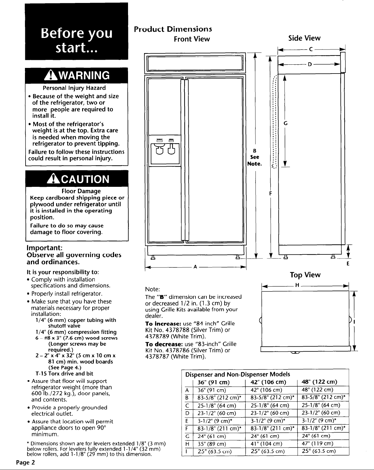
Product Dimensions
Front View
Side View
t------C
-D-
B
See
Jote.
Important:
Observe all governing codes
and ordinances.
It is your responsibility to:
l
Comply with installation
specifications and dimensions.
l
Properly install refrigerator.
l
Make sure that you have these
materials necessary for proper
installation:
l/4” (6 mm) copper tubing
shutoff valve
l/4” (6 mm) compression fitting
6 - #8 x 3" (7.6
cm) wood screws
(Longer screws may be
required.)
2 - 2" x 4" x 32"
(5 cm x 10 cm x
81 cm) min. wood boards
(See Page 4.)
T-15 Torx drive and bit
l
Assure that floor will support
refrigerator weight (more than
600 lb./272 kg.), door panels,
and contents.
l
Provide a properly grounded
electrical outlet.
l
Assure that location will permit
appliance doors to open 90”
minimum.
* Dimensions shown are for levelers extended l/B” (3 mm)
below rollers. For levelers fully extended l-l /4” (32 mm)
below rollers, add l-l /8” (29 mm) to this dimension.
Page 2
with
!I4
A-
Note:
The “B” dimension can be increased
or decreased l/2 in. (1.3 cm) by
using Grille Kits available from your
dealer.
To increase:
Kit No. 4378788 (Silver Trim) or
4378789 (White Trim).
To decrease:
Kit No. 4378786 (Silver Trim) or
4378787 (White Trim).
use “84-inch” Grille
use “83-inch” Grille
Dispenser and Non-Dispenser Models
( 36" (91 cm)
A 1 36” (91 cm)
I
B ) 83-518" (212 cm)* 1 83-518” (212 cm)* 1 83-518” (212 cm)*
C
25-1/8"(64 cm)
D 23-1/2"(60 cm)
E 3-l/2" (9 cm)*
I
F 1 83-118" (211 cm)* [ 83-118” (211 cm)* ( 83-l/8” (211 cm)*
c 24"(61 cm)
H 35"(89 cm)
I
25"
\ ,
(63.5 cm)
-
-
- LFhL
1 42"(106 cm)
1 42" (106 cm)
I
25-l /8” (64 cm)
23-1/2"(60 cm)
3-l /2” (9 cm)*
I
. ,
24" (61 cm)
41” (104 cm)
25"
(63.5 cm)
Top View
1 48” (122 cm)
1 48" (122 cm)
I
25-l /8” (64 cm)
23-1/2"(60 cm)
3-l/2" (9 cm)*
I
24" (61 cm)
47" (119 cm)
25" (63.5
‘f
E
1
cm)
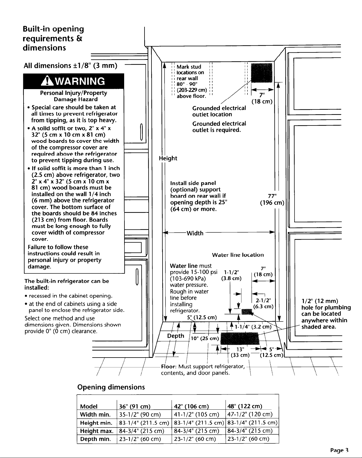
Built-in opening
requirements &
dimensions
All dimensions +1/8” (3 mm)
Personal Injury/Property
Damage Hazard
l Special care should be taken at
all times to prevent refrigerator
from tipping, as it is top heavy.
l A solid soffit or two, 2” x 4” x
32”
(5 cm x 10 cm x 81 cm)
wood boards to cover the width
of the compressor cover are
required above the refrigerator
to prevent tipping during use.
l If solid soffit is more than 1 inch
(2.5 cm) above refrigerator, two
2” x 4” x 32”
81 cm) wood boards must be
installed on the wall l/4 inch
(6 mm) above the refrigerator
cover. The bottom surface of
the boards should be 84 inches
(213 cm) from floor. Boards
must be long enough to fully
cover width of compressor
cover.
Failure to follow these
instructions could result in
personal injury or property
damage.
The built-in refrigerator can be
installed:
l
recessed in the cabinet opening.
l
at the end of cabinets using a side
panel to enclose the refrigerator side.
Select one method and use
dimensions given. Dimensions shown
provide 0” (0 cm) clearance.
(5 cm x 10 cm x
-
II
II
I I (203229
’ ’ above floor. ’ ’
cm) I I
Grounded electrical
outlet location
Grounded electrical
outlet is required.
I
Install side panel
(optional) support
board on rear wall if
opening depth is 25”
(64
cm) or more.
-Width
Water line
provide 15-l 00 psi l-1/2”
(103-690 kPa)
water pressure.
must
(1 !ZZm)
*
Water line location
(3.8 cm) V
I
l/2” (12 mm)
hole for plumbing
can be located
anywhere within
- shaded area.
Opening dimensions
Model
Width min.
Height min.
Height max. 84-3/4” (215 cm)
Depth min. 23-l /2” (60
36” (91
35-l/2” (90 cm)
83-l /4” (211.5 cm) 83-l /4” (211.5 cm) 83-l /4” (211.5 cm)
cm)
cm)
I I
I T
I I
Floor:
contents, and door panels.
, / 11 I
Must support refrigerator, l
42” (106
41-l /2” (105 cm)
84-3/4” (215 cm)
23-l /2” (60 cm)
cm)
1 (33 cm) -(12.5 cm)
\
48” (122 cm)
47-l /2” (120 cm)
84-3/4” (215 cm)
23-l /2” (60 cm)
\ \
\
Page 3
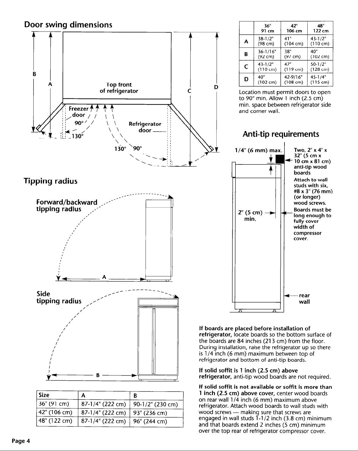
Door swing dimensions
B
1
A
Top front
of refrigerator
Location must permit doors to open
to 90” min. Allow 1 inch (2.5 cm)
min. space between refrigerator side
and corner wall.
Anti-tip requirements
Tipping radius
Forward/backward _x-xT-*--
tipping radius ,,1-’
,’
#’
I’
I
I
I
r’
I
I’
I’
Side
tipping radius ,/l’-
/
/
/
/
/
/
/
/
/I
/
I
I
V-B-
*’
_____-------____
_------_
__--
e3l
l/4” (6 mm) ma,
2” (5 cm)
min.
I
If boards are placed before installation of
refrigerator,
the boards are 84 inches (213 cm) from the floor.
During installation, raise the refrigerator up so there
is l/4 inch (6 mm) maximum between top of
refrigerator and bottom of anti-tip boards.
If solid soffit is 1 inch (2.5 cm) above
refrigerator,
locate boards so the bottom surface of
anti-tip wood boards are not required.
44
Two 2” x 4” x
32” (5 cm x
*lOcmx81 cm)
anti-tip wood
boards
Attach to wall
studs with six,
#8 x 3” (76 mm)
(or longer)
wood screws.
Boards must be
- long enough to
fully cover
width of
compressor
cover.
+ rear
wall
I
Page 4
87-l /4” (222 cm)
90-l /2” (230 cm)
If solid soffit is not available or soffit is more than
1 inch
on rear wall l/4 inch (6 mm) maximum above
refrigerator. Attach wood boards to wall studs with
wood screws - making sure that screws are
engaged in wall studs l-l /2 inch (3.8 cm) minimum
and that boards extend 2 inches (5 cm) minimum
over the top rear of refrigerator compressor cover.
(2.5 cm)
above cover,
center wood boards
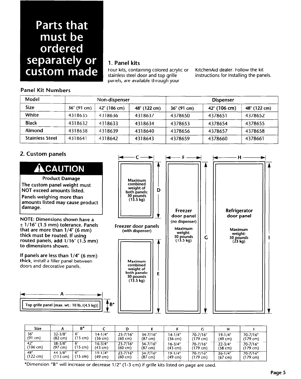
Panel Kit Numbers
1. Panel kits
Four kits, containing colored acrylic or
stainless steel door and top grille
panels, are available through your
KitchenAid dealer. Follow the kit
instructions for installing the panels.
Model
Size
White
Black
Almond
Stainless
Steel
36"
(91 cm)
4318635
4318632
4318638
4318641
2. Custom panels
Product Damage
The custom panel weight must
NOT exceed amounts listed.
Panels weighing more than
amounts listed may cause product
damage.
NOTE: Dimensions shown have a
+ l/16” (1.5 mm) tolerance. Panels
that are more than l/4” (6 mm)
thick must be routed. If using
routed panels, add l/16” (1.5 mm)
to dimensions shown.
Non-dispenser
42" (106
4318636
4318633
4318639
4318642
cm)
-C+
Freezer door panels
(with dispenser)
#I"(122
4318637
4318634
4318640
4318643
cm)
36"(91
4378650
4378653
4378656
4378659
Freezer
r
door panel
(no dispenser)
Maximum
weight:
30 ounds
(1 f.5 kg)
cm)
Dispenser
42"
(106 cm)
4378651
4378654
4378657
4378660
-H
W(122
4378652
4378655
4378658
4378661
Refrigerator
door panel
Maximum
weight:
50 ounds
33
kg)
cm)
If panels are less than l/4” (6 mm)
thick,
install a filler panel between
doors and decorative panels.
-A
Top grille panel [max. wt.:
Size
36"
(gl cm)
’
42"
(106
cm)
48"
(122 cm)
+
10 lb./(4.5 kg)]
A
32-318"
I^_ \ I- r \ ._ _
(t5.i cm)
38-318"
(97 cm)
44-3/8"
(113 cm) (15
B*
6"
(13 cm)
(6;‘5 cm) :&‘c$
6"
cm)
14-l/4"
(36
19-l 14”
(49 cm)
C
cm)
*Dimension “B” will increase or decrease l/2” (l-3 cm) if grille kits listed on page are used.
Maximum
combined
weight of
both panels:
30
(1 p.5 kg)
D
23-7/16"
(60
cm)
23-7/l 6”
(60
cm)
23-7/l 6”
(60
cm)
ounds
L
E F G
34-7/16" 14-l/4" 70-7/16"
(87 cm) (36
34-7/l 6”
(87
cm)
34-7/l 6”
(87
cm) (49 cm) (179 cm)
cm) (179 cm)
16-314”
(43
cm) (179 cm)
19-l 14”
70-7/l 6”
70-7Jl6"
H
19-l 14”
(49 cm)
22-314"
(58
cm)
26-l/4"
(67
cm)
I
70-7/16"
(179 cm)
70-7116"
(179 cm)
70-7116"
(179 cm)
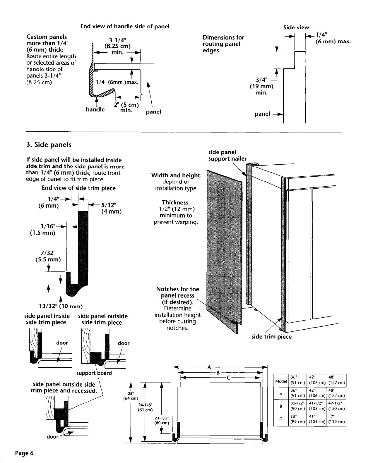
Custom panels
more than l/4”
(6 mm) thick:
Route entire length
or selected areas of
handle side of
panels 3-l /4”
(8.25
cm).
End view of handle side of panel
3- l/4”
l/4” (6mm )max.
Dimensions for
routing panel
edges
314” 314”
19 mm) 19 mm)
(
min. min.
L’ L’
f f
Side view
-7
+ l/4”
(6 mm) max.
nanare
3. Side panels
If side panel will be installed inside
side trim and the side panel is more
than l/4” (6 mm) thick,
edge of panel to fit trim piece.
End view of side trim piece
1/4”-D
(6 mm)
l/16”
(1.5 mm)
7132”
(5.5 mm)
$
--I+
+ s/32”
I I
route front
(4 mm>
min.
panel
Width and height:
depend on
installation type.
Thickness:
l/2” (12 mm)
minimum to
prevent warping.
panel panel
f f
side panel
su~~ort nailer
i
+
13/32” (10 mm)
side panel inside side panel outside
side trim piece. side trim piece.
support
side panel outside side
trim piece and recessed.
board
Notches for toe
panel recess
(if desired). \
Determine
installation height
before cutting
notches.
side trim piece
Page 6
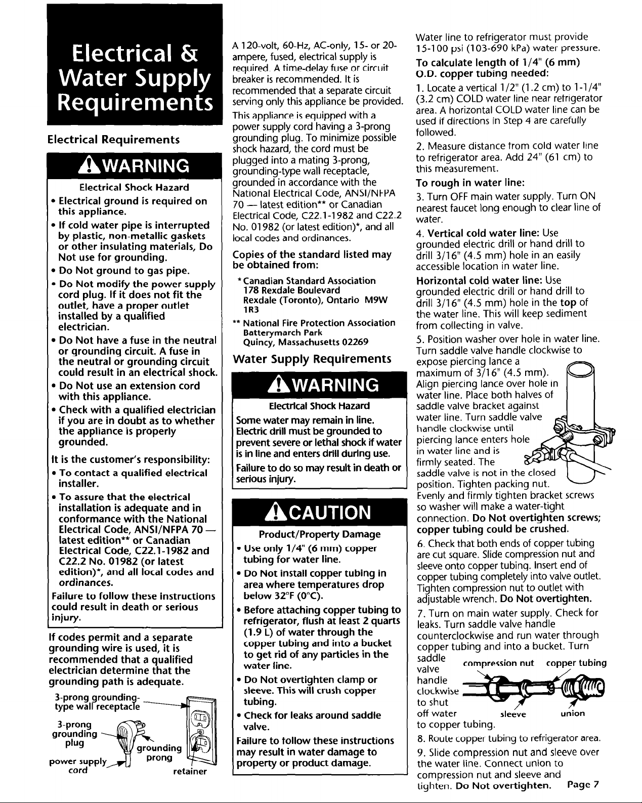
Electrical Requirements
Electrical Shock Hazard
b Electrical ground is required on
this appliance.
B If cold water pipe is interrupted
by plastic, non-metallic gaskets
or other insulating materials, Do
Not use for grounding.
b Do Not ground to gas pipe.
l Do Not modify the power supply
cord plug. If it does not fit the
outlet, have a proper outlet
installed by a qualified
electrician.
m Do Not have a fuse in the neutral
or grounding circuit. A fuse in
the neutral or grounding circuit
could result in an electrical shock.
m Do Not use an extension cord
with this appliance.
l Check with a qualified electrician
if you are in doubt as to whether
the appliance is properly
grounded.
It is the customer’s responsibility:
l To contact a qualified electrical
installer.
. To assure that the electrical
installation is adequate and in
conformance with the National
Electrical Code, ANWNFPA 70 latest edition** or Canadian
Electrical Code, C22.1-1982 and
C22.2 No. 01982 (or latest
edition)*, and all local codes and
ordinances.
Failure to follow these instructions
could result in death or serious
injury.
If codes permit and a separate
grounding wire is used, it is
recommended that a qualified
electrician determine that the
grounding path is adequate.
A 120-volt, 60-Hz, AC-only, 15 or 20ampere, fused, electrical supply is
required. A time-delay fuse or circuit
breaker is recommended. It is
recommended that a separate circuit
serving only this appliance be provided.
This appliance is equipped with a
power supply cord having a 3-prong
grounding plug. To minimize possible
shock hazard, the cord must be
plugged into a mating 3-prong,
grounding-type wall receptacle,
grounded in accordance with the
National Electrical Code, ANSVNFPA
latest edition** or Canadian
70 Electrical Code, C22.1-1982 and C22.2
No. 01982 (or latest edition)*, and all
local codes and ordinances.
Copies of the standard listed may
be obtained from:
*Canadian Standard Association
178 Rexdale Boulevard
Rexdale (Toronto), Ontario M9W
lR3
** National Fire Protection Association
Batterymarch Park
Quincy, Massachusetts 02269
Water Supply Requirements
I
Some water may remain in line.
Electric drill must be grounded to
prevent severe or lethal shock if water
is in line and enters drill during use.
Failure to do so may result in death or
serious injury.
l Use only l/4” (6 mm) copper
. Do Not install copper tubing in
l Before attaching copper tubing to
. Do Not over-tighten clamp or
l Check for leaks around saddle
Failure to follow these instructions
may result in water damage to
property or product damage.
Electrical Shock Hazard
Product/Property Damage
tubing for water line.
area where temperatures drop
below 32°F (0°C).
refrigerator, flush at least 2 quarts
(1.9 L) of water through the
copper tubing and into a bucket
to get rid of any particles in the
water line.
sleeve. This will crush copper
tubing.
valve.
Water line to refrigerator must provide
15-l 00 psi (103-690 kPa) water pressure.
To calculate length of l/4” (6 mm)
O.D. copper tubing needed:
1. Locate a vertical l/2” (1.2 cm) to l-l /4”
(3.2 cm) COLD water line near refrigerator
area. A horizontal COLD water line can be
used if directions in Step 4 are carefully
followed.
2. Measure distance from cold water line
to refrigerator area. Add 24” (61 cm) to
this measurement.
To rough in water line:
3. Turn OFF main water supply. Turn ON
nearest faucet long enough to clear line of
water.
4. Vertical cold water line:
grounded electric drill or hand drill to
drill 3/l 6” (4.5 mm) hole in an easily
accessible location in water line.
Horizontal cold water line:
grounded electric drill or hand drill to
drill 3/l 6” (4.5 mm) hole in the
the water line. This will keep sediment
from collecting in valve.
5. Position washer over hole in water line.
Turn saddle valve handle clockwise to
expose piercing lance a
maximum of 3/l 6” (4.5 mm).
Align piercing lance over hole in
water line. Place both halves of
saddle valve bracket against
I
water line. Turn saddle valve
handle clockwise until
piercing lance enters hol
in water line and is
firmly seated. The
saddle valve is not in th
position. Tighten
Evenly and firmly tighten bracket screws
so washer will make a water-tight
connection.
packing nut.
Do Not over-tighten screws;
Use
Use
top
copper tubing could be crushed.
6. Check that both ends of copper tubing
are cut square. Slide compression nut and
sleeve onto copper tubing. Inset-t end of
copper tubing completely into valve outlet.
Tighten compression nut to outlet with
adjustable wrench.
7. Turn on main water supply. Check for
leaks. Turn saddle valve handle
counterclockwise and run water through
copper tubing and into a bucket. Turn
saddle
valve
.-. -
handle
clockwise
to shut
off water
to copper tubing.
8. Route copper tubing to refrigerator area.
9. Slide compression nut and sleeve over
the water line. Connect union to
compression nut and sleeve and
tighten.
compression nut
Do Not over-tighten.
Do Not overtighten.
copper tubing
/
sleeve
u&on
Page 7
of
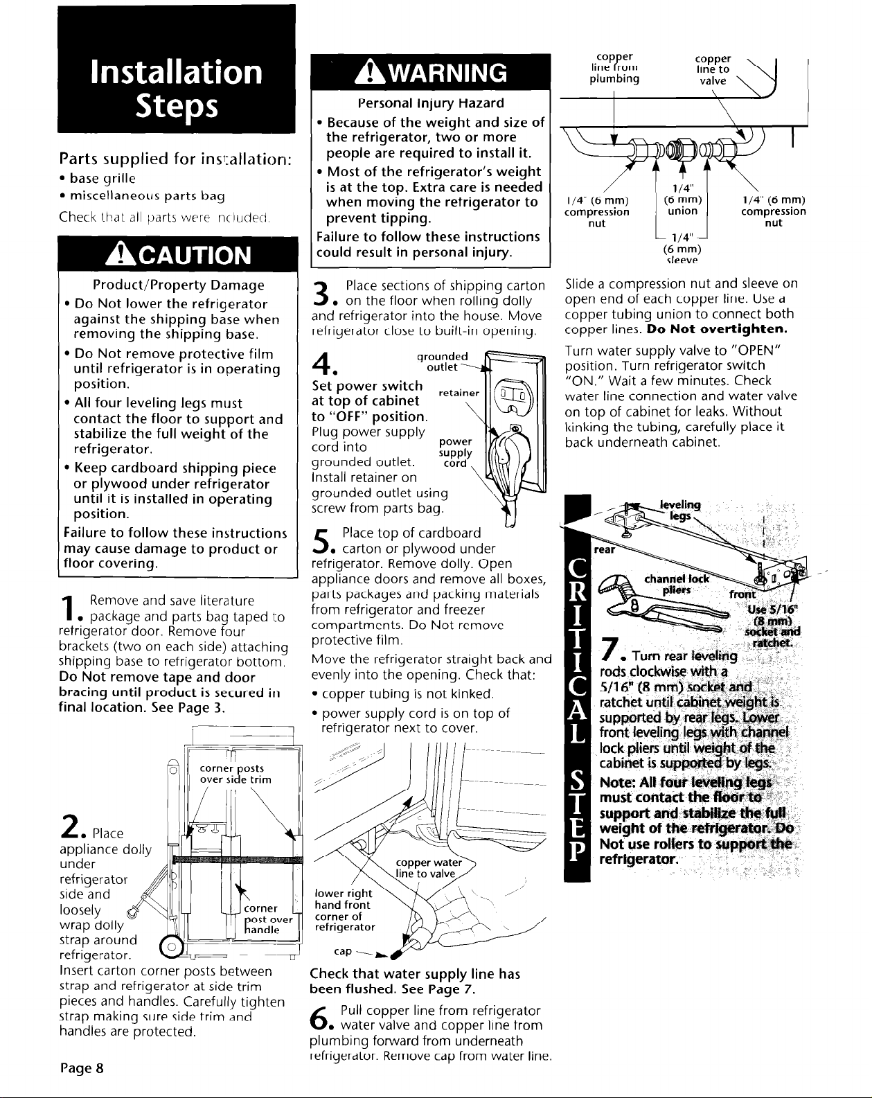
Parts supplied for ins:allation:
l
base grille
l
miscellaneous parts bag
Check l-hat all
Product/Property Damage
l
Do Not lower the refrigerator
against the shipping base when
removing the shipping base.
l
Do Not remove protective film
until refrigerator is in operating
position.
l
All four leveling legs must
contact the floor to support and
stabilize the full weight of the
refrigerator.
l
Keep cardboard shipping piece
or plywood under refrigerator
until it is installed in operating
position.
Failure to follow these instructions
may cause damage to product olr
floor covering.
Remove and save literature
1
. package and parts bag taped to
refrigerator door. Remove four
brackets (two on each side) attaching
shipping base to refrigerator bottorn.
Do Not remove tape and door
bracing until product is secured in
final location. See Page 3.
part, were nc ludetl
Personal Injury Hazard
l
Because of the weight and size of
the refrigerator, two or more
people are required to install it.
l
Most of the refrigerator’s weight
is at the top. Extra care is needed
when moving the refrigerator
prevent tipping.
Failure to follow these instructions
could result in personal injury.
Place sections of shipping carton
3
. on the floor when rolling dolly
and refrigerator into the house. Move
refrigerator close to built-in opening.
to
4
Set*power switc
at top of cabinet
to “OFF” position.
Plug power supply
cord into
grounded outlet.
Install retainer on
grounded outlet using
screw from parts bag.
Place top of cardboard
. carton or plywood under
5
refrigerator. Remove dolly. Open
appliance doors and remove all boxes,
parts packages and packing materials
from refrigerator and freezer
compartments. Do Not remove
protective film.
Move the refrigerator straight back and
evenly into the opening. Check that:
l
copper tubing is not kinked.
l
power supply cord is on top of
refrigerator next to cover.
I
\
\
l/4” (6 mm)
compression
nut
Slide a compression nut and sleeve on
open end of each copper line. Use a
copper tubing union to connect both
copper lines.
Turn water supply valve to “OPEN”
position. Turn refrigerator switch
“ON.” Wait a few minutes. Check
water line connection and water valve
on top of cabinet for leaks. Without
kinking the tubing, carefully place it
back underneath cabinet.
I I
Do Not overtighten.
(6
mm)
union
l/4”
(6
mm)
sleeve
Ye
l/4” (6 mm)
compression
nut
I
Insert carton corner posts between
strap and refrigerator at side trim
pieces and handles. Carefully tighten
strap making sure side trim and
handles are protected.
Paae 8
corner of
Check that water supply line has
been flushed. See Page 7.
Pull copper line from refrigerator
6
.
water valve and copper line from
plumbing forward from underneath
refrigerator. Remove cap from water line.

Filler panel
re uired if -
pane s are less
7
than l/4”
(6 mm) thick.
nylon
washers
(discard)
If panels are
more than
l/4” (6 mm)
thick, route
panel edges
on all sides.
/
assembiy
door
handle-
9
. Remove all taDe and door bracinq
from refrigerator and freezer doors.
Remove screws attaching handles to
door frames. Discard nylon washers
underneath screws. Slide decorative
door panels into door frames.
IGcorative
panel
If panels are less than l/4” (6 mm)
thick,
install a filler panel between
door and decorative panel.
If panels are more than l/4” (6 mm)
thick,
route panel edges on all sides.
are atigned and teveJ,
lf4~~~s iwsd ta be adjusted
kbr fight or bl or out,
bmen’&e 3/S” (9 mm) hex
hwfid screws in the tap hinge5
# dptws md to be adjusted
up or
down,
(9 rnmi~ hex head screws in
the b&torn hinges.
Adju$t doors. Tighten screws.
ftimk that doors are aligned
and levei.
loosen the 3/8
Remove door stop set screw
located in top and bottcvn
hinges using a f-7 4 Tom
wrench.
Hotd door in the desired position
and replrace ~?t crews. I# door
does not clear countertop after
door stop has been adjusted,
countertops may need to be
““mitered.
top grille
14 .
Slide top grille decorative panel
assembly up and off top grille
assembly. Release the two tethers
holding the decorative panel to the
top grille assembly.
Page 9

top grille decorative
panel assembly,
two small screws
and panel side
trim from one
side of the
decorative panel
assembly to allow
insertion of your
custom panel. Reassemble the side
trim, screws, and tethers in reverse
order. Reinstall decorative panel
assembly and pull down to secure.
---
If side panels are not used,
16
. go to Step 17.
If built-in area depth is 25” (63.5 cm)
or more,
inside the side trim or attached to the
outside of the side trim:
-
side panels can be installed
Top view
Top view
24-518”
(62 cm)
max.
L
l Outside side trim piece:
equally spaced holes into side trim
piece.
Do Not drill into side of
appliance.
to trim piece. Nail front and rear
edges of side panel to support
boards. Cover front support board
with a matching panel piece.
Attach a support board
Drill 6
Top view
\ rear wall
\
support board
- side panel
Open appliance doors and
. remove protective film from
17
door frame. Recheck water connections
at bottom of refrigerator for leaks.
Attach bottom grille to cabinet with
two screws. Install shelves and bins in
refrigerator and freezer compartments.
Set refrigerator and freezer
. compartment controls to the
18
midpoint between “COLD” and
“COLDEST.” Check that the
compressor is operating properly and
that all five lights are working.
I
24-518”
(62 ;m)
max.
l Inside side trim piece:
edge of routed side panel into trim
piece. Nail rear edge of panel to
support board.
Slide front
24-
side trim
door
If built-in area depth is less than
25” (63.5
installation according to site
restrictions. (One method is to install
a support nailer on the built-in
opening rear wall. Drill holes into side
trim. Then attach wood support to
trim. Attach side panel to wood
support and support nailer. Cover
wood support with a matching panel
piece.)
cm),
complete side panel
Part No. 2004022
0 1995 KitchenAid.
8 KitchenAid. Registered trademark
of KitchenAid.
KPtchenAid”
HOME APPLIANCES
Prepared by KitchenAid, St. Joseph, Michigan 49085
Printed in U.S.A.

Rkfrigkateurs
encastrks
91 cm (36 PO),
106 cm (42 po)
122 cm (48 po)
Important :
Lire et conserver
ces instructions.
L’installation
nbcessite
I’intervention de 2
personnes ou plus.
Important :
l
lnstallateur
instructions d’installation au
propriktaire.
l
PropriCtaire
instructions d’installation pour
rkfkrence ultk-ieure.
l
Conserver
d’installation pour consultation
par I’inspecteur local des
installations klectriques.
: Remettre les
: Conserver les
ces instructions
I I I I I I
/ I I I I I I \ \ \ \i
Y
I I I
1 , I
I I
\ \
Piece no 2004022
\
”

Risque de blessures
l
A cause du poids et de la taille du
refrigerateur, son installation necessite
I’intervention de deux personnes ou
plus.
. La plus grande par-tie du poids du
refrigerateur se trouve a la pat-tie
superieure. Manipuler le refrigerateur
avec prudence lors des deplacements,
pour qu’il ne bascule pas.
Le non-respect de ces instructions peut
@tre la cause de blessures.
Risque de dommages pour le plancher
Conserver la plaque en carton ou en
contre-plaque de I’emballage sous le
refrigerateur jusqu’a ce qu’il soit install6 a
sa position de service.
Le non-respect de ces instructions peut
@tre la cause de dommages pour le
plancher.
Dimensions du produit
Vue avant
Vue lath-ale
-C
B
Voir
remarque.
Important :
Respecter les dispositions de tous
les codes et r+glements en
vigueur.
C’est a I’installateur qu’incombe la
responsabilite de :
l
Respecter les specifications et dimensions
d’installation.
l
Installer le refrigerateur convenablement.
l
Verifier que tout le materiel necessaire a
une installation convenable est disponible:
Tube en cuivre de 6 mm (l/4 po)
avec robinet d’arret
Raccord a compression, 6 mm (l/4 po)
6 vis a bois no 8 x 7,6 cm (3
(il peut @tre necessaire d’ub user des vis
plus longues)
2 morceaux de bois de 5 cm x 10 cm x
81 cm (2 po x 4 po x 32 po) min.
(voir page 4)
Tournevis - pointe Torx T-15
l
Verifier que la resistance du plancher lui
permet de soutenir le poids du
refrigerateur (plus de 272 kg/600 lb), des
panneaux de portes et du contenu.
l
Fournir une prise de courant
convenablement reliee a la terre.
l
Verifier que I’emplacement d’installation
permet I’ouverture de la Porte du
refrigerateur a au moins 90”.
l
Les dimensions indiquk correspondent B la situation oti
les pleds de r6glage de I’aplomb depassent de 3 mm
(l/8 po) au-dessous des roulettes. Lorsque les pieds sont
totalement deploy& de 32 mm (1 l/4 po) au-dessous des
roulettes, ajouter 29 mm (1 l/8 po) ti cette dimension.
Page 2
o)
if
k-----Ad
Remarque:
La dimension “B” peut @tre augmentee ou
diminuee de 1,3 cm (l/2 po) en employant
la trousse du panneau decoratif disponible
chez votre marchand.
Pour augmenter: employer la trousse de
panneau no 4378788 (garniture argent) ou
4378789 (garniture blanche).
Pour dlminuer: employer la trousse de
panneau (83 po) no 4378786
(garniture argent) ou 4378787
(garniture blanche).
I
I 91 c-m I36 00)
_ -...
\-- I--,
A 91 cm (36 po)
B
212 cm (83 5/8 PO)*
C 64 cm (25 l/B po)
D 60 cm (23 l/2 po)
I E I 9 cm (3 l/2 DO)* I 9cm
\
G 61 cm (24 poi ’ ’
H 89 cm (35 po)
I 63,5 cm (25 po)
’
106 c
212 cm i83 ‘5/8 PO)*
64 cm (25 l/8 po)
60 cm (23 l/2 po)
I
I
8 DO)*/ 211 cm (83 l/8 DO)* 1 211 cm (83 l/8
61 cm (i4 po) ’ ’
104 cm (41 po)
63,5 cm (25 po)
Vue de dessus
k-----“------d
IT
(
Mod+les avec et sans distributeur
212 cm i83 i/i PO)*
64 cm (25 l/8 po)
60 cm (23 l/2 po)
m2po)’
] 9 cm (3 l/2 PO)’ I
61 cm (;4 po) ’
119cm(47po)
63,5 cm (25 po)
>I
PO)’

Caract&istiques et
dimensions de la cavitk
d’encastrement
TolCrance de + 3 mm (l/8 po) E
pour toutes les dimensions
Risque de blessuresldommages
. Faire attention B ce que le
rCfrigCrateur ne bascule pas; la plus
grande partie du poids du
rkfrigkrateur se trouve B la pat-tie
supkrieure.
l
Pour kiter que le rkfrigkrateur ne
bascule en tours de service, installer
un soffite massif ou deux tales en
bois de 5 cm x 10 cm x 81 cm
(2 po x 4 po x 32 po) recouvrant la
largeur du couvercle du
compresseur.
l
Si le soffite massif est pIa& b plus
de 2,5 cm (1 po) au-dessus du
rkfrigkrateur, installer deux tales en
boisdeScmxlOcmx81 cm
(2 po x 4 po x 32 po) sur le mur, A
6 mm (l/4 po) au-dessus du
GfrigCrateur. La surface infkrieure
des tales doit Ctre A 213 cm (84 po)
du plancher. Les tales en bois
doivent Stre suffisamment longues
pour recouvrir compktement la
largeur du couvercle du
compresseur.
Le non-respect de ces instructions
peut @tre la cause de blessures ou
de dommages materiels.
Le rCfrigCrateur encastrk peut &re
install6 :
l
en retrait dans I’espace disponible entre
les placards.
l
ZI I’extr6mid de la rangCe d’armoires; on
utilise alors un panneau lateral pour
recouvrir le c&6 du rkfrigerateur.
Choisir l’une des methodes et utiliser les
dimensions indiqukes. Les dimensions
indiquees laissent un dkgagement de 0 cm
(0 PO).
matkriels
-
/ I
/
/
I
0
/
/
I
Marquer la 1
position des I
poteaux du I
colombage surl
le mur arrike, I
I I
I I
i 203-229
I I
(80-90
dessus du sol.
cm I
po) au-
(7
PO)
/
Emplacemknt de la prise
de courant Clectrique
reliee a la terre.
Une prise de courant
electrique relike b la terre
est rkcessaire.
Hau
teur
Installer des supports des
panneaux latkraux (facultatifs)
sur le mur arrike si la
profondeur de la cavitk est de
64 cm (25 po) ou plus.
Largeur
EmDlacement de la canalisation d’arrivbe
d’eh
La canalisation d’arrivke
d’eau
doit fournir de I’eau
sous une pression de
103-690 kPa (15-l 00
Ib/po2). Effectuer
I’installation
preliminaire de la
canalisation d’eau avant
d’installer le refrighateur.
_12,5 cm (5 po)
-Plancher : Le plancher doit pouvoir soutenir le poids du
rkfrigkrateur, des panneaux de portes et du contenu.
3,8
cm
(1 l/2 PO)
5
196 cm
(77 PO)
- 12Scm
L
Trou de 12 mm
(l/2 po) pour le
passage de la
canalisation (g un
emplacement
quelconque dans la
- zone ombragCe).
I
L
\
\
\
Dimensions de la cavitk
Modele
Largeur min.
Hauteur min.
Hauteur max.
Profondeur
min.
91 cm (36 po)
90
cm (35 l/2 po)
21 lg5 Cm
215 cm (84 3/4 po)
60
(83 114
cm (23 l/2 po)
106 cm (42 po)
105 cm (41 l/2 po)
Po) 211,5 cm (83 l/4 po)
215
cm (84 3/4
60
cm (23 l/2 po)
po)
122 cm (48 po)
120 cm (47
209 cm (82 l/2 PO)
215 cm (84 3/4 po)
60
cm (23 l/2 po)
l/2 po)
Page 3

Dimensions pour le pivotement des portes
I :
: :
: :
:::
7
congelateur
: :
90”’ / \ \
I ’
1: :
r;+ ’
x -130”
Devant du rCfrigCrateur
/
\ i
\ \
\ \
1 <oO ‘90”
\ ‘1
\
\
- *j j
.-.-_I#. -
Rayon de basculement
___------_____
*_--
__--
,’
.’
Rayon de basculement
avant/arrikre
1,’
,’
,’
i
-
r
L
4
/
91 cm 106 cm
(36
A
B
C
D
98
(38-l /2 po)
92
(36-l/1 6 po) (38
1lOcm
(43-l /2 po)
102 cm 108 cm
1
(40
PO)
cm
cm
po)
(42
104cm
(41
119cm
(47
I(42
PO)
PO)
97
cm
po)
PO)
9/l 6
PO)/ (45 l/4 po)l
D
L’emplacement d’installation doit
permettre I’ouverture des portes a un angle
de 90” au moins. Laisser un espace d’au
moins 2,5 cm (1 po) entre le c&C du
refrigerateur et le mur formant I’angle.
Prkvention du basculement
6
mm (l/4 po) max.
7
Scm
(2 po) min.
4-1
fl
-I
Deux tales en bois
de5cmxlOcmx
81 cm(Zpox4po
›- x
32
Fixer les tales en
bois aux poteaux
du colombage
mural avec six vis &
bois no 8 x 7,6 cm
(3
po) ou plus
longues.
Les tales en bois
- utilisCes doivent
@tre assez longues
pour couvrir
totalement la
largeur du
couvercle du
compresseur.
122 cm
(48 PO)
1lOcm
(43 l/2
102 cm
(40
PO)
128cm
(50 l/2 PO)
115cm
PO).
PO)
Page 4
Rayon de basculement
lateral
/
/
/
/
/
/
/
I
I
I
I
I
i-B.
*_v-----_
/-
-’
, ,/’
/
/
/
-.
-.
+ mur
arrikre
Si les tales sont mises en places avant I’installation du
rkfrigkrateur, positionner les tales de sorte que leur base
soit a 213 cm (84 po) du plancher. Pendant I’installation,
soulever le refrigerateur afin qu’il y ait un espace de 6 mm
(l/4 po) au plus entre le haut du refrigerateur et la base
des tales antibasculement.
Si un soffite massif est install6 a
2,5
cm (1 po) audessus du rkfrigkrateur, il n’est pas necessaire d’installer
les tales en bois pour prevenir le basculement.
Si un soffite massif n’est pas disponible ou si le soffite
est place a plus de 2,5 cm (1 po) au-dessus de la partie
supkrieure, centrer les tales en bois utilisees pour la
prevention du basculement sur le mur arriere a 6 mm
(l/4 po) max. au-dessus du refrigerateur. A I’aide des vis a
bois, visser les tales en bois aux poteaux du colombage
mural - veiller a ce que les vis p&-&rent dans les poteaux
du colombage d’au moins 3,8 cm (1 l/2 po) et a ce que la
surface frontale des tales en bois soit sit&e a au moins
5 cm (2 po) au-dela de la surface
arrihe
du
couvercle
du
compresseur du refrigerateur.

1. Ensembles de panneaux
Quatre ensembles de panneaux de portes
en acrylique colon? ou en acier inoxydable
sont disponibles de votre concessionnaire
Panneaux - Numkros des ensembles
KitchenAid. Utiliser les instructions
d’installation fournies avec chaque
ensemble pour I’installation des panneaux.
1 Modele Sans distributeur
Taille
Blanc
t-
91 cm (36 po) 106 cm (42 po)
4318635 4318636 4318637 4378650 4378651 4378652
14318632 14318633
I
I
122 cm (48 po)
14318634
I
IAvec distributeur
91 cm (36 po) 106 cm (42 po)
14378653
I
14378654
I
122 cm (48 po)
14378655
Amande 1 4318638 I431 8639 1 4318640 14378656 14378657 14378658
1 Acier inoxydable 1 4318641 14318642 1 4318643
I
4378659
14378660
14378661
2. Panneaux personnalisks
-H-
I-
Panneau de Porte
du rkfrigkrateur
Poids maximal :
23
kg (50 lb)
Risque de dommages pour le produit
Le poids des panneaux personnalisks
NE
doit PAS dCpasser les valeurs
indiqukes.
L’installation de panneaux dont le
poids dkpasse la limite indiquke peut
@tre la cause de dommages pour le
produit.
REMARQUE : Tolkrance de + 1,s mm
(l/16 po) pour les dimensions indiqukes.
Les panneaux dont I’kpaisseur est
supkrieure i 6 mm (l/4 po) doivent faire
I’objet d’un usinage. Lors de I’emploi de
panneaux dkji amincis par usinage,
ajouter 1,s mm (l/16 po) aux dimensions
indiqukes.
Si I’Cpaisseur des panneaux est infkrieure 5
6
mm (l/4 PO),
remplissage entre les portes et les panneaux
decoratifs.
installer un panneau de
Si I’Cpaisseur des panneaux est supkrieure
a 6
mm (l/4 PO),
usinage.
amincir tous les bords par
-C+
Poids maximal
combine des
deux
panneaux :
13,5 kg (30 lb)
Panneaux de portes du
conoelateur (avec
d:stributeur)
Poids maximal
combine des
deux
panneaux :
135 kg
(30
7
lb)
E
Panneaux de
portes du
congklateur
(sans
distributeur)
Maximum
weight:
30 ounds
(1 g.5 kg)
I
-A
Panneau de la
L
[poids max. : 45 kg 60 lb)]
Size A
91 cm
(36 PO)
106 cm
(42 PO)
122
cm
(48 PO)
*La dimension “B” augmentera ou diminuera de 1,s cm (l/2
*La dimension “B” augmentera ou diminuera de 1,s cm (l/2
sont utilises. sont utilises.
4
grille
su erieure
82 cm 15cm
(32 3/8
PO) (6 PO)
97 cm
(38 318
113cm
(44 3/8
15cm
PO)
(6
PO)
15cm
po) (6 po)
B
B
C
36 cm
(14 l/4 PO)
43 cm
(16 314
PO)
49 cm
(19 l/4
PO) (23 7/16 po)
IL
L
60 cm
(23 7/16
60 cm 87 cm
(23 7/l 6
60 cm 87 cm
;I
D E
87 cm
(34 7/16
PO)
(34 7/l 6 po)
po)
(34 7/16 po)
po) si les trousses de panneaux d&or&ifs indiqu& 2 la page 2
po) si les trousses de panneaux dhratifs indiques 2 la page 2
-
F G
36 cm 179cm
(14 l/4
PO)
43 cm 179cm
(16 3/4 po)
49 cm 179cm
(19 l/4 po)
PO)
il.
(70 7/16
(70 7/l 6 po)
(70 7/16 po)
PO)
H
49 cm
(19 l/4
PO)
58 cm
(22 3/4 po)
67 cm
(26 l/4 po)
I
179cm
(70 7/l 6
179cm
(70 7/l 6 po)
179cm
(70 7/l 6 po)
PO)
I
-
Page 5

Vue de I’extrkmitb - c6tk poignke du panneau
Panneaux
personnalishs
d’kpaisseur supbrieure
2 6
mm (l/4 po) :
Amincir par usinage a la
toupie sur toute la
longueur ou a des
emplacements choisis
du cGtC poignke du
panneau, sur 8,25 cm
(3 l/4
PO).
8,25
cm
3. Panneaux latkraux
Si le panneau IatCral doit s’engager dans une
garniture latkrale, et si I’Cpaisseur du
panneau lateral est supkieure A 6 mm
(l/4 PO),
panneau pour qu’il puisse passer dans la piece
de garniture.
amincir par usinage le bord avant du
Vue de I’extrCmitC de la piece
de garniture laterale
Largeur et hauteur :
selon le type
d’installation.
Dimensions pour
I’usinage b la
peripherie des
panneaux
19 mm
(314
PO)
min.
panneau
tringle de clouage et
support du panneau lateral
Vue lath-ale
+6mm
(114
max.
PO)
6
mm+
(114
PO)
1,s mm j
l/16
po)
5,s mm
V/32
po)
3
10 mm (13/32 po)
panneau lateral
engage dans la piece
de garniture laterale.
4mm
(S/32
po)
panneau lateral
hors de la piece
de qarniture laterale.
Epaisseur :
Minimum 12 mm (l/2
po)
pour emp@cher le
gauchissement.
Encoches pour la
plinthe en retrait (le
cas echeant).
Determiner la hauteur
du refrigerateur
install6 avant de
decouper les
encoches.
\
-s
piece de garniture laterale
panneau lateral hors de
la piece de garniture
laterale, et en retrait.
Page 6
tringle d!app?
\
64cm
(25 PO)
I I
61011
(24
1 /a po)
I
(23 l/2
60cm
po)
Mode+ (36
91 cm 106cm
po)
(42 PO)
91 cm 106cm
A
(36 PO)
90 cm 105 cm
B
(35 l/2 po) (41 l/2 po) (47 l/2 po)
89 cm
C
(35 PO)
(42 PO)
104 cm
(41 PO)
122cm
(48 PO)
122 cm
(48 PO)
12Ocm
119cm
(47 PO)

klectrique
Risque de choc electrique
l
Cet appareil doit etre relic a la terre.
l
Si la canalisation d’eau froide comprend
des joints en plastique ou non
metalliques ou d’autres materiaux
isolants, ne pas les utiliser pour la liaison
a la terre.
l
Ne pas utiliser la canalisation de gaz
pour la liaison a la terre.
. Ne pas modifier la fiche du cordon
d’alimentation. Si la configuration de la
fiche de branchement ne correspond
pas a la configuration de la prise de
courant, demander a un Clectricien
qualifie d’installer une prise de courant
convenable.
l
Veiller a ce qu’aucun fusible ne soit
install6 en serie dans le conducteur
neutre ou le conducteur de liaison a la
terre. Cela pourrait etre la cause d’un
choc Clectrique.
l
Ne pas utiliser un cable de rallonge pour
I’alimentation de cet appareil.
. En cas de doute au sujet de la liaison a la
terre de cet appareil, consulter un
Clectricien qualifie.
C’est au client qu’incombe la responsabilite
de :
l
Contacter un Clectricien qualifie pour
I’installation.
9 S’assurer que I’installation Clectrique est
adequate et conforme aux dispositions
du Code National Electrique, ANSI/NFPA
70 - derniere edition** ou du Code
canadien des installations electriques
C22.1-1982 et C22.2 no 01982 (ou
derniere edition)‘, et tous les codes et
reglements locaux.
Le non-respect de ces instructions
pourrait causer la mar-t ou une blessure
serieuse.
Si les codes en vigueur le permettent et si un fil
distinct de liaison a la terre est utilise,. on
recommande qu’un electricien qualrfre
determine que le conducteur de liaison a la terre
prise de courant m
3 broches, reliee a
fiche de branchement
a 3 broches, reliee a la
terre
cordon d’alimentation
d’electricite
Une prise de courant de 120 V, 60 Hz, CA
seulement, 15 ou 20 A, avec fusible, doit etre
disoonible. On recommande I’emoloi d’un
fusjble temporise ou d’un disjonct’eur.
retenue
On recommande Cgalement que I’appareil
soit alimente par un circuit distinct
n’alimentant que cet appareil.
Cet appareil est equipe d’un cordon
d’alimentation dote d’une fiche de
branchement a 3 broches. Pour minimiser
le risque de choc electrique, le cordon doit
etre branche sur une prise de courant
murale correspondante, a 3 broches, reliee
a la terre, conformement aux dispositions
du Code National ilectrioue, ANSI/NFPA
70 - derniere edition*’ du bu Code
anadien des installations electriques
122.1-l 982 et C22.2 no 01982 (ou
erniere edition)*, et de tous les codes
)caux et reglements en vigueur.
In peut obtenir un exemplaire des codes
lentionnes a I’adresse suwante :
*Association canadienne de normalisation
178 Rexdale Boulevard
Rexdale (Toronto), Ontario M9W 1 R3
t National Fire Protection Association
Batterymarch Park
Quincy, Massachusetts, 02269
;pkifications de
‘alimentation en eau
Risque de choc Clectrique
II peut rester de I’eau dans la
tuyauterie d’arrivee d’eau. Lors de
I’utilisation d’une perceuse Clectrique,
veiller a ce que la perceuse soit
convenablement reliee a la terre pour
kiter un choc Clectrique grave ou
meme mortel qui surviendrait si de
l’eau penetrait dans la perceuse.
Le non-respect de cette instruction
pourrait causer la mort ou une
blessure serieuse.
Risque de dommages pour le
produit/dommages materiels
. Utiliser uniquement un tube en
cuivre de 6 mm (l/4 po) pour
I’arrivee d’eau.
l
Ne pas installer le tube en cuivre
dans un endroit ou la temperature
peut s’abaisser a moins de 0 “C
(32 “F).
. Avant de connecter le tube en cuivre
au refrigerateur, le rincer en y
faisant passer au moins 1,9 L
(2 pintes) d’eau pour Climiner tous
les debris qui ont pu s’y introduire.
l
Ne pas serrer excessivement la bride
ou le raccord, ce qui pourrait ecraser
le tube en cuivre.
l
Rechercher les fuites autour du
robinet de prise en charge.
Le non-respect de ces instructions
peut Ctre la cause de dommages pour
le produit ou d’autres dommages
materiels sous I’effet d’une fuite d’eau.
La canalisation d’eau alimentant le
refrigerateur doit fournir de l’eau sous une
pression de 103-690 kPa (15-l 00 Ib/po2).
Calcul de la longueur necessaire de la
section d’un tube en cuivre de 6 mm
(l/4 po) de diam. ext. :
1. Identifier a proximite du refrigerateur une
canalisation d’eau FROIDE verticale de 1,2 cm a
3,2 cm (l/2 po a 1 l/4 PO). On peut Cgalement
utiliser une canalisation d’eau FROIDE horizontale
si les instructions de I’etape 4 sont
scrupuleusement observees.
2. Mesurer la distance entre la canalisation d’eau
froide et le refrigerateur. Ajouter 61 cm (24 po) a
cette dimension.
Pose preliminaire de la canalisation d’arrivee
d’eau :
3. FERMER le robinet principal d’alimentation.
OUVRIR le robinet le plus proche assez longtemps
pour purger toute l’eau des canalisations.
4. Canalisation d’eau froide vetticale : Utiliser une
perceuse Clectrique reliee a la terre ou une
perceuse manuelle pour perter un trou de
4,s mm (3/l 6 po) a un emplacement facilement
accessible de la canalisation.
Canalisation d’eau froide horizontale : Utiliser
une perceuse Clectrique reliee a la terre ou une
perceuse manuelle pour perter un trou de
4,s mm (3/l 6 po) dans la par-tie superieure de la
canalisation. Ainsi, des sediments ne
s’accumuleront pas dans le robinet de prise en
charge.
5. Placer le joint sur le trou perce de la canalisation.
Faire tourner la manette du robinet de prise en
charge dans le sens horaire pour faire depasser la
pointe percante d’un maximum de 4,s mm
(3/l 6 PO). Aligner la pointe percante avec le trou
per& dans la canalisation. Placer les deux moities
de la bride de fixation du robinet de m
prise en charge contre la
canalisation. Faire tourner la
Pi
manette du robinet dans le sens
horaire jusqu’a ce que la pointe
percante penetre dans le trou de
la canalisation et soit fermement
en place. Le robinet de prise en
charge n’est pas a la
position de fermeture.
Serrer I’ecrou autour de la
tige de commande. Serrer
uniformement et fermement les vis
de bridage, afin que le joint etablisse
une connexion etanche. Ne pas serrer
excessivement; le tube en cuivre pourrait
s’ecraser.
6. Veiller a ce que les deux extremites du tube en
cuivre soient toupees a I’equerre. Enfiler I’ecrou de
compression et la virole sur le tube en cuivre.
Enfoncer completement I’extremite du tube en
cuivre dans I’ouverture du robinet. Serrer I’ecrou
de compression sur le raccord avec une cle a
molette. Ne pas serrer excessivement.
7. Ouvrir le robinet principal d’alimentation.
Inspecter pour rechercher les fuites. Faire tourner
la manette du robinet de prise en charge dans le
sens antihoraire et laisser de I’eau s’ecouler a
travers le tube en
cuivre dans un seau. ecrou de
Faire tourner la
compression
,
tube en
cuivre
/
manette dans le
sens horaire pour
interrompre
I’ecoulement de I’eau a
travers le tube en cuivre.
virole
raccord
8. Acheminer le tube en cuivre jusqu’a la zone
d’installation du refrigerateur.
9. Enfiler I’ecrou de compression et la virole
sur la
canalisation d’eau. Visser I’ecrou sur le raccord et
serrer. Ne pas serrer excessivement.
Page 7

Pikes fournies pour
I’installation :
l
grille de ventilation basse
l
Sachet de pikes
Verifier que toutes les pikes sont prkentes
Risque de dommages pour le
produit/dommages materiels
. Ne pas abaisser le kfrigkrateur sur la
base utiliske pour I’expbdition, lors de
I’extraction de la base.
l
Ne pas Bter le film protecteur avant que
le rCfrigCrateur soit b la position de
service.
l
Les quatre pieds de kglage de I’aplomb
doivent @tre en contact avec le sol et
soutenir la totalitk du poids du
rbfrigkrateur pour le stabiliser.
l
Conserver la plaque en carton ou en
contre-plaquC sous le refrigkrateur lors
de I’expCdition, jusqu’h ce qu’il soit
install6 A la position de service.
Le non-respect de ces instructions peut
Ctre la cause de dommages que subirait le
produit ou le revetement du sol.
Enlever le sachet de documents et le
1
. sachet de pikes fix& sur la Porte du
rbfrigbrateur; conserver ces articles en lieu stir.
6ter les quatre brides (deux de chaque c6t.k)
fixant la base utilisCe pour le transport en bas
du rCfrigCrateur.
adhksifs et entretoises qui immobilisent les
portes avant que le rkfrigerateur ait ktk
solidement install6 a la
position de service
I. . . .
rmale. Volr page 3.
2
. Mettre le
chariot sous le c6tk
du rkzfrigerateur et
arrimer le
r6frigCrateur avec
la sangle du
chariot, sans
trop serrer.
Inskrer les cornkes
en carton pour
proteger les angles et les poigkes entre la
sangle et le r@frig@rateur. Serrer prudemment la
sangle en Grifiant que les pikes de garniture
latbrales et les poigkes sont protPg6es.
Page 8
Ne pas 6ter les rubans
cormere en
carton sur les
Risque de blessures
l
A cause du poids et de la taille du
rkfrigkrateur, son installation
nkcessite I’intervention de deux
personnes ou plus.
l
La plus grande partie du poids du
rCfrig&ateur se trouve & la partie
supkrieure. Manipuler le
rbfrigkrateur avec prudence lors
des dCplacements, pour qu’il ne
bascule pas.
Le non-respect de ces instructions peut
@tre la cause de blessures.
Avant de deplacer le refrigkrateur sur
3
3. le plancher de la maison, sur un
chariot, placer sur le plancher les sections
de I’emballage de carton. Approcher le
r6frigPrateur prPs de I’ouverture de
I’encastrement oti il sera instalk
prise
. Pousser le
4
commutateur
d’alimentation sit&
en haut de la caisse
B la position d’arkt
(OFF).
Brancher le
de
courant reliCe
cordon d’alimentation
sur une prise de
courant blectrique
reli6e 2 la terre. Fixer la bride d
retenue sur la prise de courant
avec la vis qu’on trouve dans le
sachet de petites pikes.
Mettre une plaque en contre-plaq&
. ou en carton sous le rkfrigkateur.
5
Retirer le chariot de manutention. Ouvrir
les portes de I’appareil et 6ter toutes les
boites, les sachets de pikes et les
matkiaux d’emballage qu’on trouve dans
le compartiment de refrig6ration et le
compartiment de congglation. Ne
la pellicule protectrice.
pas 6ter
InsCrer le rPfrig6rateur dans I’ouverture
d’encastrement, en ligne droite et
uniformement. Verifier que :
l
le tube en cuivre n’est pas deform@,
6cras6, etc.
l
le cordon d’alimentation electnque est au
sommet du rbfrigkateur, prk du
couvercle.
vers robinet
d’arrivee d’eau
VCrifier que la canalisation d’arrivke
d’eau a CtC purgke. Voir page 7.
Extraire la canalisation de cuivre du
. robinet d’alimentation en eau du
6
r@fng&ateur, et tirer vers I’avant pardessous le rPfrig6rateur la canalisation de
cuivre reGe au circuit de plomberie.
canalisation en
cuivre relike au
circuit de
plomberie de la -
maison ,
canalisation en
cuivre, vers le
robinet
\
6mm
(114
PO)
de6mm
Enfiler un 6crou de compression et sa virole
sur I’extr@mit@ libre de chaque canalisation
de cuwre. Utiliser un raccord droit pour
tubes de cuivre pour raccorder les deux
canalisations de cuivre. Ne
excessivement.
pas serrer
Ouvrir le robinet d’arrike d’eau (position
OPEN). Placer le commutateur
d’alimentation electrique du refrigkateur a
la position de marche (ON). Attendre
quelques minutes. Inspecter la connexion
de la canalisation d’eau et le robinet
d’arrivee d’eau au sommet de la caisse pour
identifier les fuites kentuelles. R&ns&er la
canalisation de cuivre sous le Gfrigkateur,
en veillant a ne pas I’kraser ou la deformer.

Panneau de
remplissage
kessaire si __
I’kpaisseur du
panneau
dkcoratif est
infkrieure 21
6
mm (l/4 PO).
rondelles
de nylon
(jeter)
n
. &er tous les rubans adhesifs et
7
;i
il
Si I’kpaisseur
du panneau
dkoratif est
supkrieure B
6mm
(1 I4 PO),
amincir tous
les bords par
bCcoratif
entretoises des pottes du refrigerateur et
du congelateur. &er les vis fixant les
poignees aux cadres de portes. Enfiler les
panneaux decoratifs des portes dans les
cadres de portes.
Si I’Cpaisseur du panneau dkoratif est
infCrieure a 6 mm (l/4 PO), installer un
panneau de remplissage entre la Porte et
le panneau decoratif.
Si I’kpaisseur du panneau dkcoratif est
supkrieure a 6 mm (l/4 PO), amincir tous
les bords par usinaqe a la toupie.
51 UR sdte ma& n’est pas
dispnble OLI si be soffite est ptaci B
plus de 2,5 an (1 po) audessus du
ri$fri#ra&2w, centrer &es tales en
Ws w-itibascutenent sur le mur
ati$re, ii 6 mm (IM PO) max. audews du r&ig&atew. A l’aide des
vis (3. tmis, visser ies tales en b&s aux
potearlx du colornbage mural - veiller
a ce que les vis p&&rent dans les
poteaux du colambage d’au mains
3,8 cm (1 l/2 po) et Z ce que la
s&ace fmntak ck tales en buis soit
i plack a au mains S cm (2 po) au-
de& de la surface arrike du couvercle
montage de la
Mbrieure
Faire coulisser le panneau decoratif de la
grille superieure vers le haut pour le &parer
de la grille superieure. Detacher les deux
cordons qui relient le panneau decoratif a la
grille superieure.
Page 9

Vue de dessus
panneau dkoratif de
la grille superieure
deux petites vis et la
garniture laterale du
panneau sur un
c&S du panneau
decoratif, pour
permettre I’inseftion
du panneau
personnalise. Reinstaller la garniture laterale,
les vis et les cordons de retenue, dans I’ordre
inverse du demontage. Reinstaller le
panneau decoratif et tirer vers le bas pour
I’immobiliser.
. Si aucun panneau IatCral n’est
16
utilisb, passer A I’btape 17.
Si la profondeur de la cavitb
d’encastrement est de 63,5 cm (25 po) ou
plus, on peut engager les panneaux lateraux
i I’interieur de la garniture laterale, ou les
fixer a I’exterieur de la garniture laterale.
lanchette d’appui lanchette d’appui
T T
II
62
cm
l
Pike de garniture laterale externe :
Perter 6 trous equidistants dans la piece
de garniture laterale. Ne pas perter
dans le cBtC de I’appareil. Fixer une
planchette d’appui sur la piece de
garniture. Clouer les bords avant et
arriere du panneau lateral sur les
planchettes d’appui. Recouvrir la face
avant des planchettes d’appui avec un
morceau de panneau assorti.
l\l I
Vue de dessus
Ouvrir les portes de I’appareil et
. oter la pellicule protectrice de
17
I’encadrement des portes. Inspecter de
nouveau les raccords de connexion de
tuyauterie situ& en bas du refrigerateur
pour rechercher les fuites.
Fixer la grille de ventilation de la base avec
deux vis. Installer les @tag&es et caissons
dans les compartiments de refrigeration et
de congelation.
Regler les thermostats du
. refrigerateur et du congklateur au
18
point median entre les rep&es FROID et
TEMPERATURE MINIMALE. Verifier que le
compresseur et les cinq lampes
fonctionnent normalement.
Vue de dessus
(24 ~0)
62 cm
(24 518 po)
max.
1L
l
Pike de garniture laterale interne :
Enfiler le bord avant aminci du panneau
lateral dans la piece de garniture. Clouer
le bord arriere du panneau sur la
planchette d’appui.
rniture laterale
planchette d’appui
Si la profondeur de la cavitC
d’encastrement est infkrieure 2 63,s cm
(25 PO), executer I’installation des
panneaux lateraux en tenant compte des
restrictions imposees par les
caracteristiques du site d’installation. (Une
methode consiste a installer une
planchette de clouage et d’appui sur le
mur arriere de la cavite d’encastrement.
Perter des trous dans la garniture laterale.
Fixer ensuite la planchette d’appui a la
garniture. Fixer le panneau lateral sur la
planchette d’appui et la planchette de
clouage. Recouvrir la planchette d’appui
avec un morceau de panneau assorti.)
Piece no 2004022
0 1995 KitchenAid
@ KitchenAid. Marque deposee de
KitchenAid.
KitchenAEcD”
APPAREILS MiNAGERS
Prepare par KitchenAid, St. Joseph, Michigan 49085
lmprime aux k-U.

36 pulg. [91 cm.]
42 pulg. [106 cm]
y 48 pulg. [122 cm]
Refrigerador
Empotrado
Importante:
Leer y guardar
estas instrucciones.
Se requiere 2 0 miis
personas para
instalar.
Importante:
l
Instalador: Dejar instrucciones
con el propietario.
l
Propietario: Cuardar
instrucciones para referencia en
el futuro.
l
Cuarde estas instrucciones de
instalacih para uso del inspector
elktrico.
I I I
I
I
I I
I
I
I
I
\ \
I \
Pieza No. 2004022
\
\ \

Peligro de Heridas
l
Por el peso y tamafio del
refrigerador, se requiere dos o mk
personas para su instalacibn.
l
La mayor parte del peso del
refrigerador se encuentra en la
secci6n superior. Se requiere de
cuidado especial al mover el
refrigerador, para prevenir su
inclinacibn.
La falta de atenci6n a estas
instrucciones pueden causan heridas.
Vista Frontal
DIMENSIONES
Vista Lateral
-C
B
Ver
Nota.
La falta de atenci6n a esta instrucci6n
puede daiiar la superficie del piso.
Observar todas las
disposiciones y regulaciones
del case.
Es su responsabilidad:
l
Observar las disposiciones sobre
instalaci6n y dimensiones
. lnstalar el refrigerador en forma
correcta.
l
Verificar que dispone de 10s siguientes
materiales necesarios para una
instalaci6n correcta:
tuberia de cobre de l/4 pulg. [6 mm]
con vilvula de cierre
accesorio de compresi6n de l/4 pulg.
b5
mm1
6 tornillos para madera #8 x 3 pulg.
[76 mm]
[es posible que requiera tornillos m&
largos]
2 tiras de madera de 2 pulg. x 4 pulg.
[S cm x 10 cm x 81 cm] min.
[ver p6gina
T-15 Tornillo Torx
l
Confirmar que el piso puede soportar un
refrigerador de un peso [mayor a 600
lbs.1272 kg.], paneles de puertas y su
contenido interior.
l
Proveer un enchufe el&trico con su
debida tierra.
l
Verificar que el lugar permite la apertura
de la puerta del refrigerador por lo
menos 90”.
l
Las dimensiones indicadas surten efecto para 10s
niveladores extendidos l/8 pulg. 3 mm] debajo de 10s
rodillos. Para niveladores extendidos 1 -l/4 pulg.
[32 mm] debajo de 10s rodillos, aumentar l-1/8 pulg.
[29 mm] a esta dimensi6n.
Pigina 2
Nota:
La dimensi6n “6” puede ser
aumentada o disminuida l/2 pulg.
(1,3 cm) usando 10s Juegos de Rejilla
disponibles de su distribuidor.
Para aumentar: use el Juego de
Rejilla de “84 pulgadas” N” 4378788
(Moldura Plateada) o 4378789
(Moldura Blanca).
Para disminuir: use el Juego de
Rejilla de “83 pulgadas” N” 4378786
(Moldura Plateada) o 4378787
(Moldura Blanca).
Modelos Con Expendedor
36 pulg (91 cm)
A 36 pulg (91 cm)
B
83-5/8 oula (212 cm)* 83-5/8 oulq (212 cm)* 83-5/8 pulq (212 cm)*
C 25-l/8 pulg (64 cm)
D
23-l /2 pulg (60 cm)
E 3-l /2 pulg (9 cm)*
1 F 1 83-l I8 oula (211 cm)‘1 83-l I8 PUIIJ (211 cm)*183-l/8 pulq (211 cm)*
c
24 pulg (61 cm)
H
I
25 oula (63.5 cm)
I .,.
35 pulg (89 cm)
42 pulg (106 cm)
42 pulg (106 cm)
25-l /8 pulg (64 cm)
23-l /2 pulg (60 cm)
3-l /2 pulg (9 cm)*
24 pulg (61 cm)
41 pulg (104 cm)
25 oula (63.5 cm)
--+
. -.
Vista Superior
-
48 pulg (122 cm)
48 pulg (122 cm)
25-l /8 pulg (64 cm)
23-l /2 pulg (60 cm)
3-l /2 pulg (9 cm)*
-
24 pulg (61 cm)
47 pulg (119 cm)
25 oulq (63.5 cm)
J
I
,I

DIMENSIONES Y
REQUERIMIENTOS PARA
EMPOTRAR
Todas las dimensiones + l/8
pulg. [3 mm]
Peligro de heridas/Daiios
a la propiedad
l
Se debe poner atenci6n en todo
moment0 para evitar que el
refrigerador se incline, puesto que
la parte superior soporta la mayor
parte del peso.
l
un sofito o dos de 2 pulg. x 4 pulg.
x 32 pulg. [5 cm x 10 cm x 81 cm]
de madera s6lida para cubrir el
ancho de la tapa del compresor
para prevenir inclinacirk durante el
uso.
l
Si el sofito s6lido sobresale m6s de
1 pulg. [2.5 cm] encima del
refrigerador, se requiere entonces
instalar dos Gras de madera de 2
pulg. x 4 pulg. x 32 pulg. [S cm x 10
cm x 81 cm] en la pared, l/4 pulg.
[6 mm] sobre la tapa del
refrigerador. La superficie inferior
de las tiras de madera debe
permanecer 84 pulgadas [213 cm]
del piso. Las Gras de madera deben
ser lo suficientemente largos para
cubrir el ancho de la tapa del
compresor.
La falta de observancia a estas
instrucciones puede causar heridas o
dafios a la propiedad.
El refrigerador empotrado puede
instalarse:
9 dentro de la cavidad de 10s gabinetes
l
al final de 10s gabinetes utilizando un
panel lateral para cubrir el lado del
refrigerador.
Elija un mCtodo y utilice las dimensiones
adjuntas. Estas dimensiones permiten una
6rea libre de 0 pulg. [0 cm].
-
1
II
I I Marque el
I I sitio de la
I I columna en I I
I ! la Dared
I I posterior II
” 80 - 90 pulg. ”
[203-229 cm]
desde el piso.
I
Utu Ira
lnstalar el soporte del
panel lateral [optional]
en la pared posterior si la
apertura tiene una
profundidad mayor de
i5 pulg. [64 cm]*o m6s.
+
PAncho
Tuberia de
agua debe
disponer de una
presih de 15-l 00
psi [103-690 kPa].
Efectuar instalacih (3*8 cm)
de la tuberia de
agua antes ae
I I
I i
II
Enchufe elkctrico con
tierra
Se requiere un enchufe
ektrico con tierra
Seiial de tuberia de agua
.
I/ r7
(18 cm)
/
77 pulg
(196 cm)
l
Ranura para
plomeria de
l/2 pulg. [12 mm]
puede ser situada
en cualquier lugar
- dentro del Circa
sombreada.
-
_i/.,
/ I I
Dimensiones de apertura
Modelo
Ancho min.
Altura min.
Altura max.
Profundidad min.
36 pulg (91 cm)
35-l /2 pulg (90 cm)
83-l /4 pulg (211.5 cm) 83-l /4 pulg (211.5 cm)
84-3/4 pulg (215 cm)
23-l /2 pulg (60 cm)
Piso: Debe soportar el refrigerador, w--
contenldo y puertas.
42 pulg (106 cm)
41-I /2 pulg (105 cm)
84-3/4 pulg (215 cm)
23-l /2 pulg (60 cm)
48 pulg (122 cm)
47-l /2 pulg (120 cm)
83-l /4 pulg (211.5 cm)
84-3/4 pulg (215 cm)
23-l /2 pulg (60 cm)
I
\
P6gina 3

Dimensih de Puertas
/I \\
90"' / \ \
/
Puerta del
congelador
Angulo de inclinacih
Angulo de inclination
Adelante/atras .--*
I
I
I
I
r’
,’
,’
I
I
I
I
I
A
A
36
91 cm
38-l/2
A (98
cm)
36-l/1 6
B (92cm)
43-l/2
’ (1lOcm)
D 40
PUlLI
(102 cm)
pulg
pulg
pulg 38 pulg
pulg 47 pulg
42
pulg
106
41 pulg
(104 cm)
(97
cm)
cm
48 Pub
122
cm
43-l /2 pulg
(1lOcm)
40
pulg
(102 cm)
50-l 12 pulg
(119 cm)
(128 cm)
42-9/l 6 pulg 45-1 I4 pulg
(108 cm)
(115 cm)
La instalaci6n permanente debe permitir
un angulo de apertura para las puertas de
minim0 90”. Dejar un espacio minim0 de
1 pulg. [2.5 cm] entre la pared lateral del
refrigerador y la pared esquinera.
Preventivo de inclinacih
l/4 [6 mm] max.
DOS tiras de
madera para
* prevenir la
inclination de
2 pulg. x 4 pulg.
x 32 pulg. [5 cm x
10 cm x 81 cm 1.
Fijar a las
columnas
mediante seis
tornillo para
- madera #8 x 3
pulg. [76 mm]
[o m6s largos].
Las tiras de
madera deben
ser
suficientemente
largas para cubrir
completamente
el ancho de la
tapa del
compresor.
48
pulg (122 cm)
P6gina 4
Angulo de inclination /‘-
Lateral
/
/
/
/
/
/
I
I
87-l/4
//’
/
/
/
/
/
pulg (222 cm) 90-l /2 pulg
87-l /4 pulg (222 cm)
(230
cm)
e Pared
trasera
Si se coloca las tiras de madera antes
a instalar el
refrigerador, sitlie las tiras de tal manera que la superficie
inferior de las mismas se encuentren a 84 pulg. [213 cm]
desde el piso. Durante el proceso de instalacirk, levante el
refrigerador hasta dejar un espacio maxim0 de l/4 pulg. [6
mm] entre la patte superior del refrigerador y la superficie
inferior de las tiras de madera.
Si se encuentra un sofito solid0 de 1 pulg. [2.5 cm] sobre
el refrigerador, no se requiere tiras de madera para prevenir
la inclination del refrigerador.
Si no existe un sofito solido, o si el sofito es mayor a 1
pulg. [2.5 cm] sobre la cubierta, centre las tiras de madera
en la pared trasera a l/4 pulg. [6 mm] maxim0 sobre el
refrigerador. Fije las tiras a las columnas de la pared
mediante tornillos para madera, verificando que 10s tornillos
se encuentran dentro de las columnas por lo menos l-1 /2
pulg. [3.8 cm], y que las tiras de madera sobrepasan por lo
menos 2 pulg. [5 cm] sobre la secci6n superior del area
posterior de la cubierta del compresor del refrigerador.

Nlimero del juego de paneles
Modelo
Tamaiio
Blanc0
36 Pulg (91 cm) 42 pulg (106 cm) 48 pulg (122 cm) 36 pulg (91 cm) 42 pulg (106 cm)
4318635
r4318632
I I
Almendra 4318638 4318639
(Acero lnoxidable 1 4318641
Sin expendedor
4318636
14318633 14318634
14318642
1. Juegos de Paneles
Su distribuidor KitchenAid dispone de
cuatro juegos de paneles acrilicos a color
acero inoxidable para puettas y la rejilla
Con expendedor
4318637
I
4318640 4378656 4378657
14318643
4378650
14378653
I
14378659
superior. Siga 10s pasos indicados en las
instrucciones de 10s paneles su instalacion.
0
48 pulg (122 cm)
4378651
(4378654
I
4378652
1 4378655
4378658
14378660
( 4378661
2. Paneles a medida
Daiio al product0
El peso de 10s paneles fabricados
a medida NO DEBE EXCEDER 10s pesos
indicados.
El sobrepeso de 10s paneles puede
causar dafios al producto.
NOTA: Las dimensiones indicadas
permiten una
tolerancia de +- l/16 pulg. [1.5 mm].
Paneles de m6s de l/4 pulg. [6 mm]
deben tupirse. Si se utiliza paneles
tupidos, aumente l/16 pulg. [1.5 cm] a
las dimensiones indicadas.
Si 10s paneles son de un grosor inferior
a l/4 pulg. [6
relleno entre las puertas y 10s paneles
decorativos.
Si 10s paneles son de un grosor mayor a
l/4 pulg. [6
filos del panel, en todos sus lados.
mm],
instale un panel de
mm],
pase el tupi sobre 10s
Peso m6ximo
combinado
de
10s dos
aneles:
0 libras
D
[13.5 kg]
Panel de puerta del
congelador
[sin expendedor]
Peso mhimo
combinado
de
10s dos
aneles:
P
0 libras
[13.5 kg]
Paneles de las
puertas del
con elador
con
P
expendedor]
Peso m6ximo:
30 libras
[13.5 kg]
-HH
Panel de puerta
del refrigerador
Peso m6ximo:
50 libras
t23 kg1
r
I
Panel superior de la rejilla [peso miximo:
10 lbV4.5 kg]
l
La dimension “B” aumentara o disminuira l/2 pulgada (1,3 cm) si se usan 10s juegos de rejillas indicados en la pagina 2.
P6gina 5

Carte del filo del panel lado de la manija
Corte lateral
Paneles a medida con un
rosor mayor a l/4 pulg.
6
mm]:
a
Pasar el
tupi sobre la
3-l/4 pulg
totalidad
del lar 9 o o sobre irreas
especi icas
de 10s paneles
del lado de la
!??apul~. [8.25 cm]
3. Paneles laterales
5
el panel lateral se instala
dentro de la moldura lateral y si
el panel tiene un grosor mayor a
l/4 pulg. [6 mm], pase el tupi sobre
el filo frontal del panel para fijar la moldura.
Corte del filo del panel latera
1/16pul +
(1.5 mm
3
Ancho y altura
depende del tipo
de instalacih
Crosor
l/2 pulg [12 mm]
minim0 para
prevenir
deformidades
Dimensiones para
tupir 10s filos
del panel
Dimensiones para
tupir
filbs del pan<1
314
pul
(19 mm
min.
Panel
f I/4
3
(6
mm) max.
pulg
7132
pul
(5.5 mm
Moldura interior
del panel lateral
Moldura exterior ahuecada
7
13/32 pulg (10 mm)
del panel lateral
Moldura exterior
del panel lateral
Tira de sopotte
Ranura para el
list6n del z6calo
[si se desea] \
Determinar la altura
antes
de efectuar 10s
tortes
I
.
LB-
;--c-;
v
Corte lateral
Mode'o (91
A
B
C
36
36
pulg
(91
35-l/2
(90cm)
35
pulg
(89
pulg
cm)
cm)
cm)
pulg
42
(106
42
(106
41-l/2
(105
41
(104
pulg
cm)
pulg
cm)
cm)
pulg
cm)
pulg
48
(122
40
(122
47-l/2
(120
47
(119
pulg
cm)
pulg
cm)
pulg
cm)
pulg
cm)
Pigina 6

Conexiones Ektricas
Peligro de choque electric0
l
Esta unidad requiere conexion a
tierra
9 Si la tuberia de agua fria se
encuentra cubierta por material
plastico, sell0 no-medlicos u otro
tipo de aislamiento, NO UTILIZAR
corn0 tierra.
l
No utilizar la tuberia de gas coma
tierra.
l
No modificar el alambre electric0 de
la unidad. Si este no se adapta al
enchufe, cambie el enchufe con la
ayuda de un electricista calificado.
l
No mantener el fusible en posici6n
neutro o circuit0 de tierra. Si el
fusible se encuentra en position
neutro o circuit0 de tierra, puede
causar un choque electrico.
l
No utilizar un cable de extension con
esta unidad.
l
Verifique con un electricista
calificado si la unidad se encuentra
conectada a tierra correctamente.
Es responsabilidad del cliente:
l
Llamar un instalador electrico
calificado.
. Verificar que la instalacion electrica
es correcta y en conformidad con 10s
codigos electricos nacionales
ANSI/NFPA 70, ultima edition’,
ademas de todas las normas y
ordenanzas municipales al efecto.
Si no se cumplen estas instrucciones se
puede causar una lesion grave o aun la
muerte.
Si las normas lo permiten, y si se utiliza
un cable separado coma tierra, se
recomienda que un electricista
calificado determine la conexion de
tierra correcta.
Caja de pared con tierra.
de enchufe triple ------+%
Enchufe
triple con
tierra
Alambre
electric0
Oerra w
Retenedor
Se requiere una fuente electrica de 120
voltios, 60 Hz, CA solamente, con fusible
de 15 0 20 amperios. Un fusible de
tiempo diferido es recomendable. Es
tambien recomendable que un circuit0
separado sea provisto para este artefacto.
Este artefacto esta equipado con un
cordon para corriente con enchufe de tres
puntas para puesta a tierra. Para
minimizar el peligro de choque electrico,
el cordon debe estar enchufado a un
receptaculo de pared puesto a tierra, de
acuerdo con el Codigo National de
Electricidad, ANSVNFPA 70 - ultima
edition l ,
y todos 10s codigos y
ordenanzas locales.
Copias del estandar listado pueden ser
obtenidos en:
l
Asociaci6n National para Protection de
lncendios
Batterymarch Park
Quincy, Massachusetts 02269
Requerimiento para el
Suministro de Aqua
Peligro de Choque Electrico
Un poco de agua puede permanecer
en la tuberia.
El taladro electrico debe ser puesto a
tierra para prevenir choque sever0 o
letal si el agua que se encuentra en la
tuberia entra en el taladro durante el
uso del mismo.
De lo contrario se puede causar una
lesion grave 0 sun la muerte.
Producto/Dafio a la propiedad.
l
Use solamente tuberia de cobre para
suministro de agua de l/4” (6mm)
l
No use tuberia de cobre en zonas
donde la temperatura sea menor
que 32°F (0’)
l
Antes de unir la tuberia de cobre al
refrigerador, haga correr por lo
menos 2 cuartos (1.9L) de
agua por la tuberia de cobre a un
balde para limpiar la impurezas en la
tuberia de agua.
l
No ajuste en forma excesiva la
abrazadera o casquillo. Esto puede
machacar la tuberia.
l
Controle que no haya perdidas
alrededor de la montura de la
valvula.
La falta de seguir estas instrucciones
puede producir daiio de agua a la
propiedad o al producto.
La tuberia de suministro de agua al
refrigerador debe proveer 15-l 00 psi (103
- 690 kPa) de presion.
Para calcular la longitud de tuberia de
cobre de D.E. l/4” (6mm) necesitada:
1. Localice la tuberia vertical de aoua fria de
l/2“ (1.2cm) o l-l /4“ (3.2cm) m>s cerca del
refrigerador. Una tuberia horizontal de agua fria
puede ser usada, si se sigue con cuidado las
direcciones en el paso 4.
2. Mida la distancia de la tuberia de agua fria al
refrigerador. Agregue 24” (61 cm) a esta
medida.
Para pre-instalar la entrada de agua :
3. Cierre el suministro de agua. Abra el grifo
mas cercano durante el tiempo suficiente para
vaciar la tuberia de agua.
4. Tuberia de agua fria vertical: Use un
taladro electric0 puesto a tierra, o un taladro de
mano para hater una perforation de 3/l 6”
(4.5mm), en un lugar facilmente accesible de la
tuberia.
Tuberia de agua fria horizontal: Use un
taladro electrico puesto a tierra, o un taladro de
mano para hater una perforation de 3/l 6”
(4.5mm) en la parte superior de la tuberia de
agua. Esto es para prevenir que el sediment0 se
junte en la valvula.
5. Coloque la arandela sobre el agujero en la
tuberia de agua. Cire el vistago de la vilvula en
el sentido de las agujas del reloj para exponer la
lanceta petforadora a un maxim0 de 3/l 6”
(4.5mm). Coloque en linea la lanceta de
perforation con el agujero en la
tuberia. Coloque las dos mitades
de la montura de la valvula en la
tuberia de agua. Cire el vastago de
la valvula en el sentido de las
agujas del reloj hasta que la
lanceta de perforation entre en
el agujero de la tuberia y
quede firmemente
asentada. La valvula de
la montura no esta en la
position cerrada. Apriete
la tuerca de la empaquetadura en
forma pareja y firmemente apriete 10s tornillos
del soporte, para que la arandela forme una
conexion contra perdidas. No apriete
demasiado 10s tornillos; la tuberia de cobre
puede resultar machacada.
6. Controle que ambas terminaciones de la
tuberia de cobre esten cortadas en escuadra.
Deslice la tuerca de presion y casquillo en la
tuberia de cobre. lnserte la termination de la
tuberia de cobre completamente en la vdlvula
de salida. Apriete la tuerca de presion con una
llave ajustable. No apriete demasiado.
7. Abra el suministro de agua. Controle que no
haya perdida. Cire el vistago de la valvula en el
sentido
contrario de
Tuerca,fe presidn
Tuberia
,de cobre
las agujas del
reloj y haga
correr el agua
la tuberia de c
a un balde. Gire el vastago de la vdlvula en el
sentido de las agujas del reloj para cerrar el
agua.
8. Cuie la tuberia de cobre al area del
refrigerador.
9. Deslice la tuerca de presion y casquillo en la
tuberia de agua. Conecte la union a la tuerca
de presion y casquillo y ajuste. No apriete
demasiado.
PLgina 7

Partes suministradas para la
instalacih:
l
rejilla de la halt,
l
balsa con partes varias
Verifique que
incluldas.
Daiios al producto/propiedad
l
No baje el refrigerador contra la
base de embalaje cuando remueve
la base de embalaje.
l
No remueva la pelicula protectora
hasta que el refrigerador se
encuentre en posici6n de operacidn.
l
Todas las cuatro patas niveladoras
deben de estar en contact0 con el
piso para soportar y estabilizar todo
el peso del refrigerador.
l
Mantenga la pieza del embalaje
hecha de cart6n o de madera
laminada debajo del refrigerador
hasta que este estk instalado y en
posici6n de operaci6n.
El incumplimiento de estas
instrucciones puede causar danos al
product0 o a la cubierta del piso.
Remueva
1
. literatura y la bolsa de partes pegada
a la puerta del refrigerador. Remueva 10s
cuatro soportes (dos a cada lado) que
sujetan la base del embalaje a la parte de
abajo del refrigerador.
cinta ni el anclaje de la puerta hasta que
el product0 se encuentre asegurado en
su posici6n final. Ver
pigina 3.
lado del
lnserte 10s postes
esquineros de cart6n entre la correa y el
refrigerador en las guarniciones de 10s
costados y en las manijas.
Cuidadosamente apriete la correa
asegurindose que las guarniciones de 10s
lados y las manijas estk protegidas.
P6aina 8
tO(lcli Id5 pdrtc 5 Ikl/ I/,:)
y guarde el paquete con
No remueva la
77
Peligro de Lesiones Personales
l
Debido al peso y tamafio del
refrigerador, se requiere de dos o
rnk personas para su instalacibn.
l
La mayor parte del peso del
refrigerador se encuentra en la
parte de arriba. Cuando se mueve el
refrigerador es necesario tener un
cuidado extra para prevenir que se
vuelque.
El incumplimiento de estas
instrucciones puede traer coma
consecuencia lesiones corporales.
. Coloque secciones del cart6n de
3
embalaie en el piso cuando ruede la
carretilla y el refrigerador dentro de la
casa. Mueva el refrigerador cerca de la
abertura empotrada.
4
Colique el
interruptor
Toma corriente
con conexih a
tierra
de corriente situado
encima del mueble a
la posici6n “OFF”.
Enchufe el cord6n de Cor&jn
suministro de
corriente en el toma
corrlente con
conexi6n a tierra.
lnstale el retk en el toma
corriente conectado a tierra
usando un tornillo de la balsa de
partes.
Coloque la parte de arriba del
. embalaje de cart6n o de madera
5
laminada debajo del refrigerador. Remueva
la carretilla. Abra las puertas del artefacto y
remueva todas las cajas, paquetes con
partes y material de empaque de 10s
compartimientos del refrigerador y de la
nevera. No remueva la pelicula protectora.
Mueva el refrigerador directamente hacia
at& en forma pareja dentro de la abertura.
Verifique que:
l
la tuberia de cobre no est6 retorcida
l
que el cord6n de suministro de corriente
se encuentra encima del refrigerador
cerca a la cubierta.
Tuberia de cobre
ara agua hacia
a velvula
P
de
suministr
o de
corriente
Verifique que la tuberia de suministro
de agua ha sido enjugada. Ver p6gina 7.
. Saque hacia adelante la tuberia de
6
cobre de la v6lvula de agua del refrigeradol
y la tuberia de cobre de la plomeria de
debajo del refrigerador.
cobre de la
/
Tuerca de
presih de
l/4” (6 mm)
Deslice una tuerca de presl6n y un
casquillo en el extremo abierto de cada
tuberia de cobre. Use una uni6n de tuberia
de cobre para conectar ambas tuberias de
cobre.
Uni6n de
l/4”
(6
mm)
Casquillo
de I/4”
(6
mm)
\
Tuerca de
presih de
l/4” (6 mm)
No sobreajuste.
Abra la v6lvula de sumlnistro de agua a la
.,
powon
refrigerador en la posici6n “ON”. Espere
unos minutos. Verifique que no haya goteo
en la conexi6n de la tuberia de agua o en
la v6lvula de agua encima del mueble. Sin
torcer la tuberia, col6quela nuevamente
con cuidado debajo del mueble.
“OPEN”. Ponga el interruptor del
ae 31 w
(8 mni
alkate de derre
acanalado
. Gire las varillas de nivelaci6n
7
sentida del reloj usando una Have y
tubo de 5/l 6” (8 mm) hasta q&e el
mueble est+ soportado par tas patas
traseras. Baje las patas nivekdoras
frontales usando un alicate de cierre
acanalado hasta que el peso de!
mueble caiga sobre las patas.
Nota: fodas #as cuatro patas
heladoras deben de estar en
contact0
y estabilizar
ion
el piso para soportar
todo el peso
del
refrigerador. No uttlice to&Ids
para soportar el refrigerador.
al

NJertas.
kloque un
live1 contra la
mte de atr&
fe la
iuamici6n de
a puerta, en
a guia de la
1 gaveta de
tortalizas y en la guia de la canasta
k $ nevera tal corn0 se muestra.
kjuste las patas niveladoras
tdelante y las
a derecha e izquierda
ltrhs hasta que el refilgerador este a
live1 y a la altura apropiada de la
tbertura. Verifique que tas cuatro
jatas niveladoras hacen contact0
el piso y soportan todo el peso
lel refrigerador. las puertas deben
je estar instatadas cuando se hate la
tivelacidn .
. Remueva todas las cintas y 10s
anclajes para puertas de las puertas del
refrigerador y de la nevera. Descarte las
arandelas de nylon de debajo de 10s
tornillos. Deslice 10s paneles decorativos
dentro de 10s marcos de las puertas.
Si 10s paneles son menores que l/4’
(6
mm) de espesor,
relleno entre la puerta y el panel
decorative.
Si 10s paneles son de m6s de l/4”
(6
mm) de espesor,
panel en todos sus lados.
puertas del refrigerador coma las de
la nevera esten alineadas y a nivel.
Si es necesario ajustar las puertas
I
lacia
adentro
derecha o izquierda, afloje tos tornillos
de cabeza hexagonal de 3/8” (9 mm)
I
!n las bisagras de arriba.
ii es flecesario ajustar la5 puertas
%acfa arriba o abajo, afloje 10s
1 tornillos de cabeza hexagonal de 3/8”
9 mm) en ias bisagras de arriba.
1
Ajuste
ornillos. Verifique que las puertas
tstin alineadas y a nivel.
variltas niveladoras de
instale un panel ‘de
burile 10s bordes del
“ Verifique que tanto las
o afuera, o hacia la
las puertas. Apriete 10s
de
de la part@ de
. Reemplace las manijas de
I I
a puerta. Verifique que en la
;uperior ambas manijas estiin
rlineadas.
ii Las manijas no esdn aYneadas,
Ifloje todos 10s torniltos de las
nanijas y ajktetas hacia arriba o
lacia abajo. Apriete 10s tornillos.
ii alguno de 10s tomillos de Ia
>uerta blanca ha sido daiiado,
eemplkelo con otro dd paquete
ie oartes.
Tornilios de l/4”
(6 mm) locatizados
-decorativti
----
\
.
parte
\ 1’1 \
lr
Verifique que las puertas se abren
holgadamente. Si fuese necesario
ajuste el vaivkn de la puerta de la
siguiente forma:
Retire ta reji tla superior removiendo
cuatro torniltos de l/4” (6 mm)
localizados detr6s del conjunto del
panel decorative.
Tomlio
Remueva el conjunto de tornillos de
tope de puerta localizados en las
bisagras de arriba y de abajo usando
una ilave Torx T-l 5.
Sostenga la puerta en la posici6n
deseada y reemplace el conjunto de
tornillos. Si la puerta no despeja el
mostrador despuk de que 10s topes
para las puertas han sido ajustados,
10s mostradores necesitan ser
biselados.
Torx T-15. Tape de
la puerta fijado a 909 o a
130% para topes de vaivin
de la puerta.
I/
Centre la tabla
I
Cubierta .
Las tabias deben de ser to suficiente
largas para cubrir completamente la
cubierta del compresor.
.
13
Si techo
(2.5 cm) por endma del
refrigerador, las tatias de madera
antivudcos no son PeU5arias.
Si techo scilido no exfste o @stir a
m&s de 1 pulgada I25 cm) por
encima del refrigerador, localice 10s
parantes de la pared en la abertura
para el refrigerador. Centre una tabla
de
mlximo l/Z” (6 mm) encima del
refrigerador.
madera a 10s parantes de la pared
utilizando tomiltos para madera -
asegurando que 10s tornllos se
introduzcan coma minima 1 l/2”
(3.8 cm) en 10s parantes. Sujete una
segunda tabla
la primera tabla. Las tablas
madera deben de exienderse coma
minima 2 putgadas (5 cm) sobre la
parte posterior de arriba de la
cubierta del compresor del
refrigerador.
h
14
decorative de la rejilla superior hacia arriba
y afuera del conjunto de la rejilla superior.
Suelte las dos ataduras que sujetan el panel
decorative al conjunto de la rejilla superior.
s6lidu esth a 1 pulgada
madera en la pared de at&
Sujete
de
Coniunto de la
reji iia superior
. Deslice el conjunto del panel
Dos tablas
antivuelcos de
ujete a ios
arantea de
la pared
con s&s
tornillos
oaea
la
tabta de
mddera al frente de
de
Conjunto del
P6gina 9

Ensamblaje del panel
decorative de la rejilla
superior,
. Remu
15
10s dos tornillos
pequefios y la
moldura lateral del
panel de un lado
del panel
decorative para
introducir el panel a
medida. Vuelva a armar la moldura lateral,
tornillos y anclajes en orden inverso. Vuelva
a instalar et panel decorative y tire hacia
abajo para fijar.
. Si no utiliza paneles laterales,
16
vaya al pas0 17.
Si la profundidad del drea construida es
25 pulg. [63.5 cm] o m6s, 10s paneles
laterales pueden instalarse dentro de la
moldura lateral o conectados al exterior de
la moldura lateral:
Corte superior
Corte superior
d trasera
pra de sopot-te
Panel lateral
&%l,
max.
. Exterior de moldura lateral: Petfore 6
agujeros espaciados equitativamente en la
moldura lateral. No pet-fore el
electrodomkstico. Conecte una tira de
soporte a la moldura. Clave 10s filos
frontales y posteriores del panel lateral
para apoyo de las tiras. Cubra la tira de
apoyo frontal con un panel similar.
Carte superior
oldura lateral
Pared trasera
Abra la puerta de la unidad y
. remueva la pelicula protectora del
17
marco de la puerta. Vuelva a verificar que
no existe fugas de las conexiones de agua
en la parte inferior del refrigerador.
lnstale la rejilla inferior al gabinete por
medio de dos tornillos. lnstale las repisas y
cajones en el refrigerador y congelador.
Ajuste 10s controles de
. temperatura del refrigerador y
18
congelador al punto medio entre “COLD”
[FRIO] Y “COLDEST” [MUY FRIO]. Verifique
que el compresor se encuentra funcionando
correctamente, al igual que las cinco lutes.
red trasera
Tira de soporte
- Panel lateral
g- Moldura lateral
Puerta
I
b
l
Interior de moldura lateral: Deslice el
filo frontal del lado pasado con el tupi del
panel dentro de la moldura. Clave el filo
posterior del panel a la tira de soporte.
oldura lateral
Si la profundidad del 6rea construida es
menor de 25 pulg. [63.5 cm], complete
la instalaci6n del panel lateral de acuerdo
a las restricciones del sitio. [Un m&do es
de instalar una tira clavada de apoyo en la
pared trasera del la apertura del &ea
construida. Petfore agujeros en un Iado de
la moldura. Luego junte el soporte de
madera a la moldura. Conecte el panel
lateral al soporte de madera y soporte
clavado. Cubra el soporte de madera con
un panel similar]
Pieza No. 2004022
0 1995 KitchenAid
@ KitchenAid. Marca Registrada
de KitchenAid.
Preparados por KitchenAid, St. Joseph, Michigan 49085
lmpreso en 10s EE.UU
 Loading...