

Page 1
36” (91 cm),
42” (106 cm)
and
48” (122 cm)
Built-In
Refrigerators
Important:
Read and save
these instructions.
Installation
requires 2 or more
people.
Important:
l
Installer:
Instructions with the
homeowner.
l
Homeowner:
Instructions for future reference.
l
Save
Instructions for the local
electrical inspector’s use.
Leave Installation
Keep Installation
these Installation
.:* 2.
*;,
*:. *> .:*
.:* + ~3 e;. .:. “:- .:,
f e:. .:* .!. .:. *:.
.:. *:.
.:‘ q. .:.
.:. .:* I
Part No. 2003757
Page 2
Injury Hazard
Because of the weight and size
of the refrigerator, two or more
people are required to install it.
Most of the refrigerator’s
weight is at the top. Extra care
is needed when moving the
refrigerator to prevent tipping.
Failure to follow these
instructions could result in
injury.
Keep cardboard shipping piece or
plywood under refrigerator until it
is installed in the operating
position to protect floor covering.
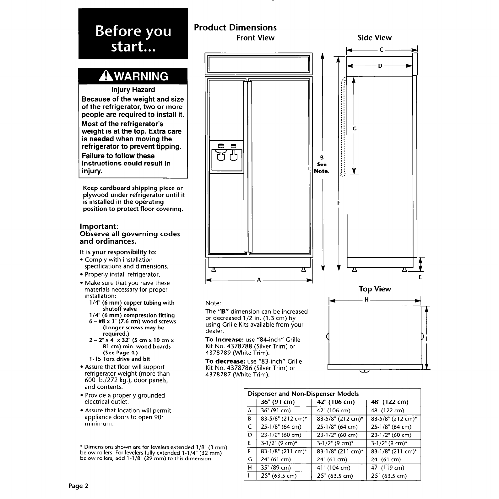
Product Dimensions
Front View
-c
-
-D-
‘:
::
::
: :
: :
::
: :
: :
::
::
::
I *
; :
; :
: :
: :
: :
: :
::
::
m:
:.:
Side View
Important:
Observe all governing codes
and ordinances.
It is your responsibility to:
l
Comply with installation
specifications and dimensions.
l
Properly install refrigerator.
l
Make sure that you have these
materials necessary for proper
installation:
l/4” (6 mm) copper tubing with
shutoff valve
l/4” (6 mm) compression fitting
6 - #8 x 3” (7.6 cm) wood screws
(Longer screws may be
required.)
2 - 2” x 4” x 32” (5 cm x 10 cm x
81 cm) min. wood boards
(See Page 4.)
T-15 Torx drive and bit
l
Assure that floor will support
refrigerator weight (more than
600 lb./272 kg.), door panels,
and contents.
l
Provide a properly grounded
electrical outlet.
l
Assure that location will permit
appliance doors to open 90”
minimum.
Note:
The
“B”
dimension can be increased
or decreased l/2 in. (1.3 cm) by
using Grille Kits available from your
dealer.
To increase:
use “84-inch” Grille
Kit No. 4378788 (Silver Trim) or
4378789 (White Trim).
To decrease:
use “83-inch” Grille
Kit No. 4378786 (Silver Trim) or
4378787 (White Trim).
Dispenser and Non-Dispenser Models
~~
-I2
t.!l
E
Top View
* Dimensions shown are for levelers extended l/8” (3 mm)
below rollers.
below rollers, add l-1 /8” (29 mm) to this dimension.
For levelers fully extended
l-l /4” (32 mm)
Page 2
D
23-l /2” (60 cm) 23-l/2” (60 cm)
E
3-l 12” (9 cm)*
3-l/2” (9 cm)*
23-l/2” (60 cm)
3-l /2” (9 cm)*
Page 3
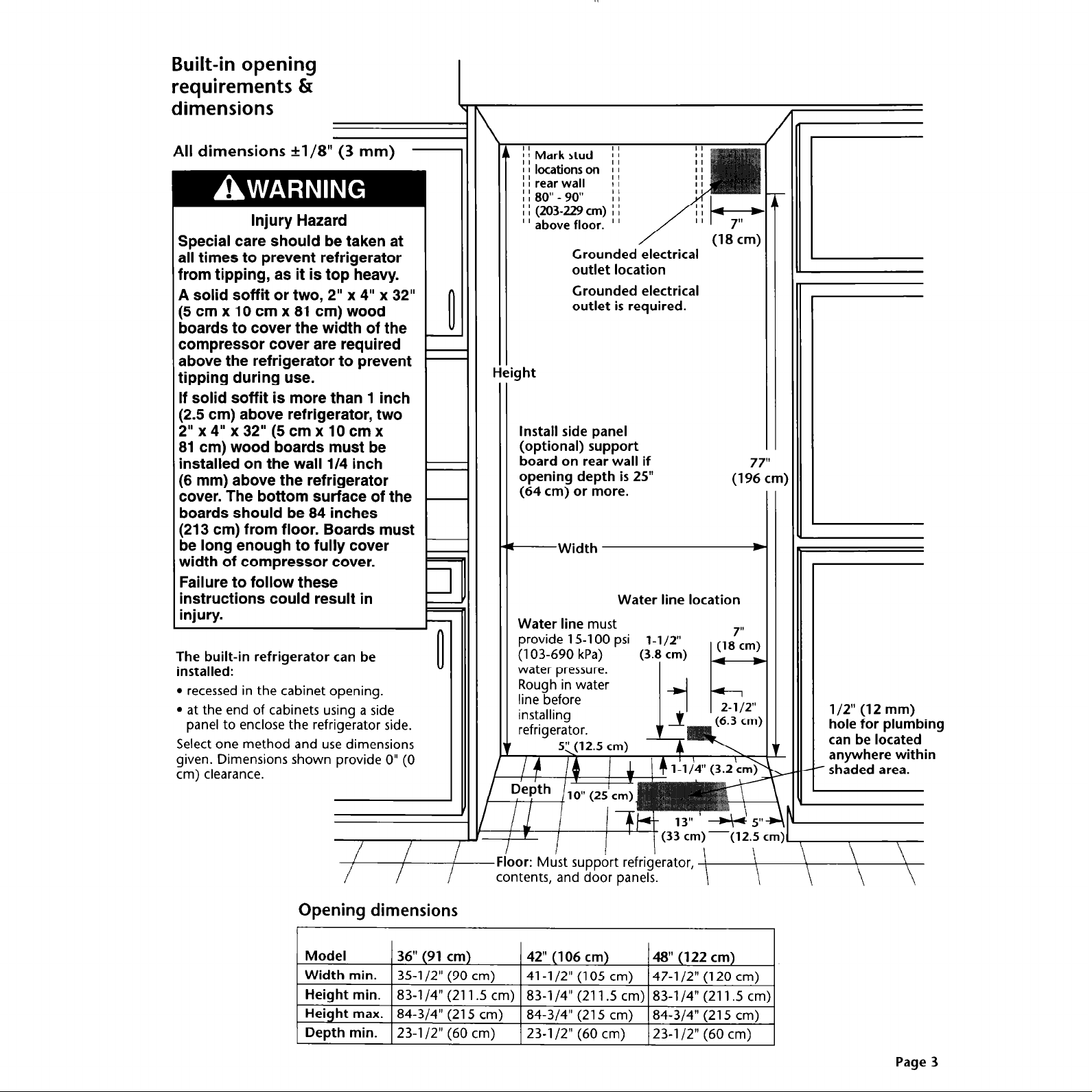
Built-in opening
requirements Q
dimensions
\
All dimensions *l/8” (3 mm)
Injury Hazard
Special care should be taken at
all times to prevent refrigerator
from tipping, as it is top heavy.
A solid soffit or two, 2” x 4” x 32”
(5cmxlOcmx81cm)wood
boards to cover the width of the
compressor cover are required
above the refrigerator to prevent
tipping during use.
If solid soffit is more than 1 inch
(2.5 cm) above refrigerator, two
2” x 4” x 32” (5 cm x 10 cm x
81 cm) wood boards must be
installed on the wall l/4 inch
(6 mm) above the refrigerator
cover. The bottom surface of the
boards should be 84 inches
(213 cm) from floor. Boards must
be long enough to fully cover
width of compressor cover.
Failure to follow these
instructions could result in
injury.
The built-in refrigerator can be
installed:
l
recessed in the cabinet opening.
l
at the end of cabinets using a side
panel to enclose the refrigerator side.
Select one method and use dimensions
given. Dimensions shown provide 0” (0
cm) clearance.
-
i 1 Mark stud
I I locations on
I I rear wall
; ! 80” - 90”
I I (203-229 cm) I I
” above floor. ”
II
II
II
II
Grounded electrical
outlet location
Grounded electrical
outlet is required.
0
Install side panel
(optional) support
board on rear wall if
7
opening depth is 25”
(64 cm) or more.
-Width
Water line location
Water line
provide 15-l 00 psi
(103-690 kPa)
water pressure.
Rough in water
line before
installing
refrigerator.
must
(3.8 cm)
(12.5 cm)
l-l/2”
I k-4
(19zl)
b
c
(1 87im)
l/2” (12 mm)
hole for plumbing
can be located
anywhere within
- shaded area.
/
/
Opening dimensions
r
Model 36” (91 cm)
Width min.
Height min.
Height max. 84-3/4” (215
Depth min.
/
I
35-l/2” (90 cm)
83-l /4” (211.5 cm)
23-l /2” (60
-Floor:
cm)
cm) 23-l /2” (60 cm)
Must support refrigerator,
contents, and door panels.
42” (106 cm)
41-l /2” (105 cm) 47-l /2” (120 cm)
83-l /4” (211.5 cm) 83-l /4” (211.5 cm)
84-3/4” (215
cm)
48” (122 cm)
84-3/4” (215
23-l /2” (60 cm)
cm)
Page 3
Page 4
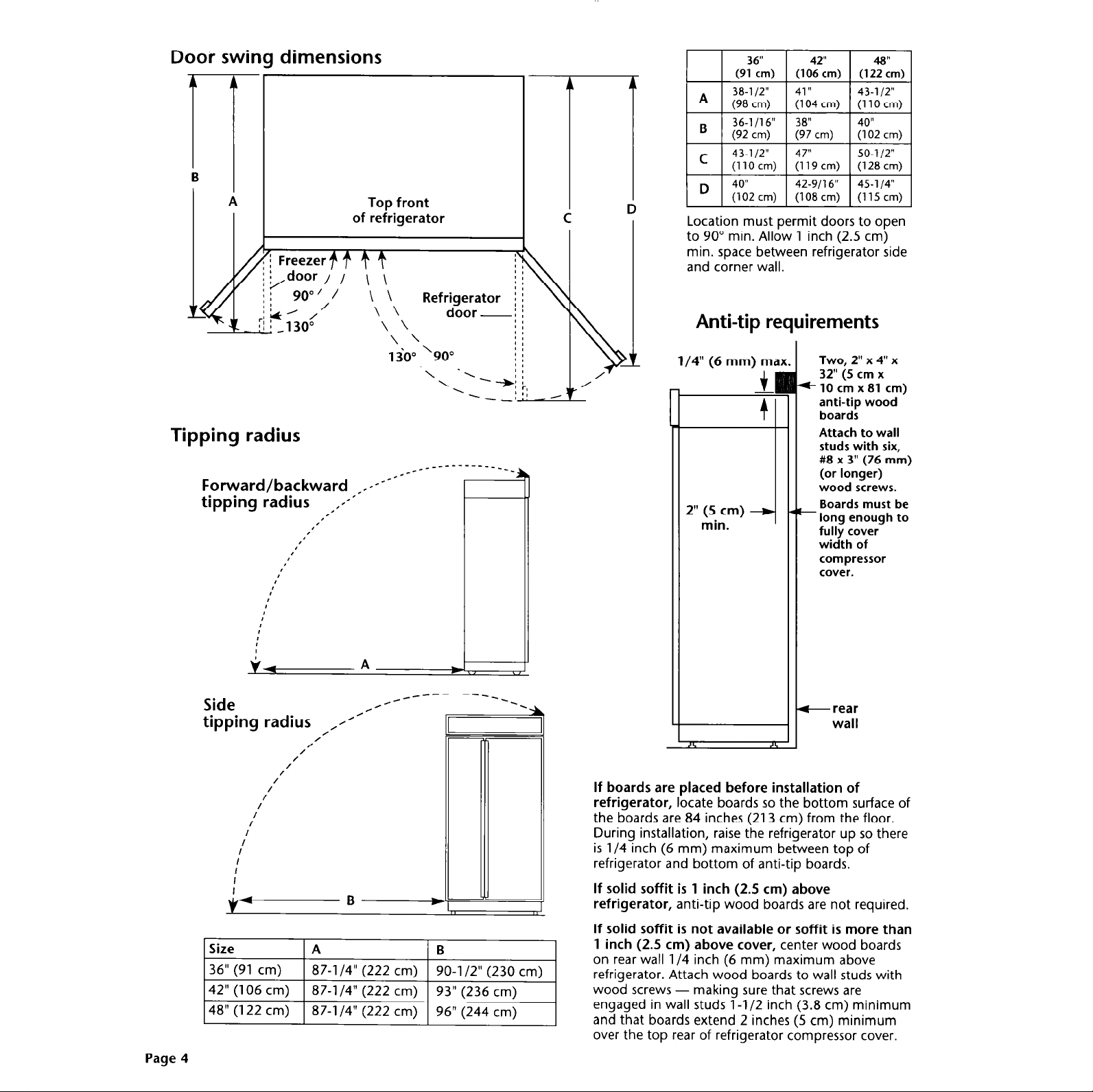
Door swing dimensions
of refrigerator
/door / I \ \
90”‘/ \\
L’ /
/
Top front
\ \
door-,
Location must permit doors to open
to 90” min. Allow 1 inch (2.5 cm)
min. space between refrigerator side
and corner wall.
Anti-tip requirements
Tipping radius
Forward/backward ,1-----1--
tipping radius ,,--’
I’
I’
8’
8’
:
I
v+
Side
tipping radius ,//’
/
I/
/
/
I
I
I
,’
I’
I
I
I
I
I
I
I
I
/
/
/
/
/
/
/
/----------‘--:
A W
L
1
/4” (6
1
If boards are placed before installation of
refrigerator,
the boards are 84 inches (213 cm) from the floor.
During installation, raise the refrigerator up so there
is l/4 inch (6 mm) maximum between top of
refrigerator and bottom of anti-tip boards.
locate boards so the bottom surface of
2”
min.
mm) ma]
f
fl
(5 cm)
Two, 2” x 4” x
32” (5 cm x
*lOcmx81 cm)
anti-tip wood
boards
Attach to wall
studs with six,
#8 x 3” (76 mm)
(or longer)
wood screws.
_ Boards must be
long enough to
fully cover
width of
compressor
cover.
-rear
wall
Page 4
Size A B
36” (91 cm)
42” (106 cm) 87-l /4” (222 cm)
48” (122 cm)
87-l /4” (222 cm)
87-l /4” (222 cm)
90-l /2” (230 cm)
93” (236 cm)
96” (244 cm)
\ I
If solid soffit is 1 inch (2.5 cm) above
refrigerator,
If solid soffit is not available or soffit is more than
1 inch
on rear wall l/4 inch (6 mm) maximum above
refrigerator. Attach wood boards to wall studs with
wood screws - making sure that screws are
engaged in wall studs 1 -l/2 inch (3.8 cm) minimum
and that boards extend 2 inches (5 cm) minimum
over the top rear of refrigerator compressor cover.
anti-tip wood boards are not required.
(2.5
cm) above cover,
center wood boards
Page 5

Panel Kit Numbers
1. Panel kits
Four kits, containing colored acrylic or
stainless steel door and top grille
panels, are available through your
KitchenAid dealer. Follow the kit
instructions for installing the panels.
Model
Size
White 4318635
Black
Almond 4318638
Stainless Steel 4318641
36” (91
4318632
cm)
2. Custom panels
The custom panel weight must
NOT exceed amounts listed.
Panels weighing more than
amounts listed may cause product
damage.
NOTE: Dimensions shown have a
+ l/16” (1.5 mm) tolerance. Panels
that are more than l/4” (6 mm)
thick must be routed. If using
routed panels, add l/16” (1.5 mm)
to dimensions shown.
If panels are less than l/4” (6 mm)
thick,
install a filler panel between
doors and decorative panels.
Non-dispenser
42” (106
4318636 4318637
4318633 4318634
4318639 4318640 4378656 4378657 4378658
4318642 4318643 4378659 4378660 4378661
cm)
Freezer door panels
48” (122
Maximum
combined
weight of
b;;” op:$ss:
(1p.5 kg)
(with dispenser)
Maximum
combined
weight of
both panels:
30 ounds
(1p.S kg)
cm)
T
36” (91
4378650 4378651
4378653
(no dispenser)
E
cm)
Freezer
door panel
Maximum
weight:
30 ounds
(I!.5 kg)
Dispenser
42”
(106 cm)
1 4378654
-H-
48” (122 cm)
4378652
1 4378655
Refrigerator
door panel
Maximum
weight:
50 ounds
CA kg)
I
4
Top grille panel [max. wt.: 10 lb./(45 kg)]
‘Dimension “B” will increase or decrease l/2” (l-3 cm) if grille kits listed on page are used.
A,
Page 5
Page 6
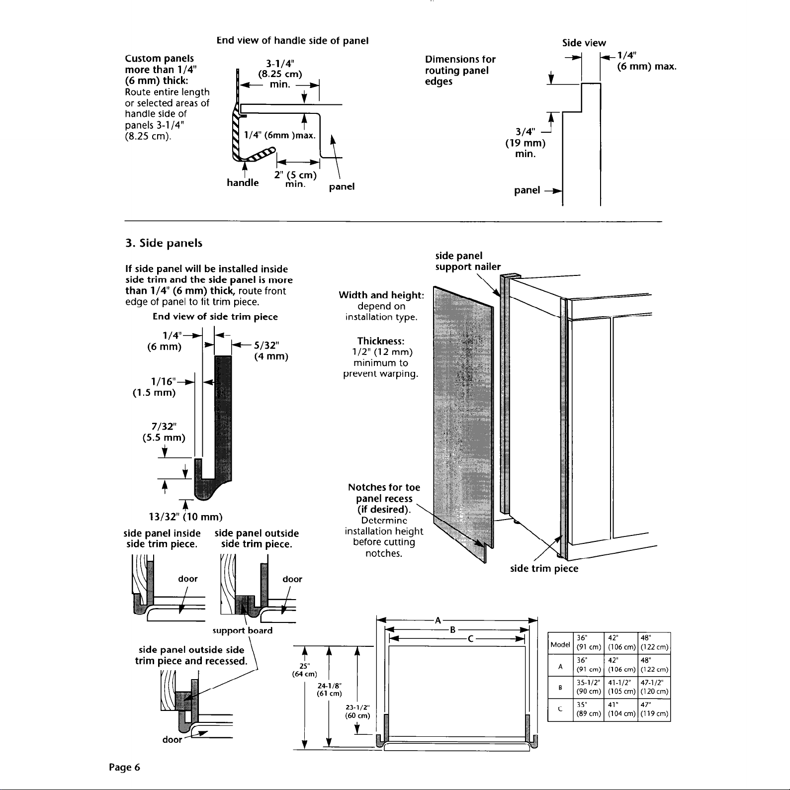
End view of handle side of panel
Custom panels
more than l/4”
(6 mm) thick:
Route entire length
or selected areas of
handle side of
panels 3-l /4”
(8.25 cm).
3. Side panels
If side panel will be installed inside
side trim and the side panel is more
than l/4” (6 mm) thick,
edge of panel to fit trim piece.
End view of side trim piece
route front
Width and height:
depend on
installation type.
Dimensions for
routing panel
edges
side panel
support nailer
. .
314”
(19 mm)
min.
panel
f-
-I
Side view
+ l/4”
(6
mm) max.
(6
mm)
l/16”+
(1.5 mm)
7/32”
(5.5 mm)
i
t
+
T
13/32” (10 mm)
side panel inside
side panel outside
side trim piece.
support
side panel outside side
trim piece and recessed.
(4 mm)
side trim piece.
\-
board
\
Thickness:
l/2” (12 mm)
minimum to
prevent warping.
Notches for toe
panel recess
(if desired). \
Determine
installation height
before cutting
notches.
-A
v
side trim piece
Model
t
36” 42” 48”
(91 cm) (106cm) (122cm)
36” 42” 48”
A
(91 cm) (106cm) (122cm)
35-112” 41-l/2” 47-l/2”
B
(90cm) (105cm) (12Ocm)
35”
C
(89cm) (104cm) (119cm)
3
41 ”
47”
Page 6
Page 7
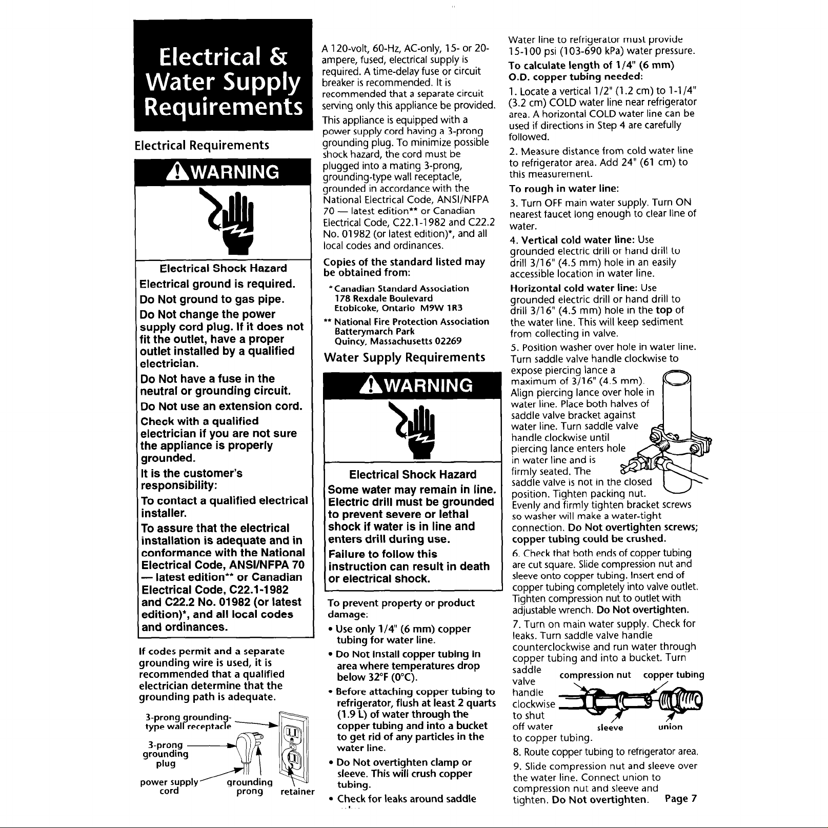
Electrical Requirements
Electrical Shock Hazard
Electrical ground is required.
Do Not ground to gas pipe.
30 Not change the power
supply cord plug. If it does not
fit the outlet, have a proper
Dutlet installed by a qualified
electrician.
Do
Not have a fuse in the
neutral or grounding circuit.
Do Not use an extension cord.
Check with a qualified
electrician if you are not sure
the appliance is properly
grounded.
It is the customer’s
responsibility:
To contact a qualified electrical
installer.
To assure that the electrical
installation is adequate and in
conformance with the National
Electrical Code, ANSVNFPA 70
- latest edition** or Canadian
Electrical Code, C22.1-1982
and C22.2 No. 01982 (or latest
edition)+, and all local codes
and ordinances.
If codes permit and a separate
grounding wire is used, it is
recommended that a qualified
electrician determine that the
grounding path is adequate.
3-prong groundin type wall receptac e p ?
I .
pow;;;;ppIy’ grounding
prong
A 120-volt, 60-Hz, AC-only, 1.5 or 20ampere, fused, electrical supply is
required. A time-delay fuse or circuit
breaker is recommended. It is
recommended that a separate circuit
serving only this appliance be provided.
This appliance is equipped with a
power supply cord having a 3-prong
grounding plug. To minimize possible
shock hazard, the cord must be
plugged into a mating 3-prong,
grounding-type wall receptacle,
grounded in accordance with the
National Electrical Code, ANSVNFPA
70 - latest edition** or Canadian
Electrical Code, C22.1-1982 and C22.2
No. 01982 (or latest edition)+, and all
local codes and ordinances.
Copies of the standard listed may
be obtained from:
*Canadian Standard Association
178 Rexdale Boulevard
Etobicoke, Ontario M9W lR3
l
* National Fire Protection Association
Batterymarch Park
Quincy, Massachusetts 02269
Water Supply Requirements
Electrical Shock Hazard
Some water may remain in line.
Electric drill must be grounded
to prevent severe or lethal
shock if water is in line and
enters drill during use.
Failure to follow this
instruction can result in death
or electrical shock.
To prevent property or product
damage:
l Use only l/4” (6 mm) copper
tubing for water line.
l Do Not install copper tubing in
area where temperatures drop
below 32°F (OOC).
l Before attaching copper tubing to
refrigerator, flush at least 2 quarts
(1.9 L) of water through the
copper tubing and into a bucket
to get rid of any particles in the
water line.
l Do Not over-tighten clamp or
sleeve. This will crush copper
tubing.
. Check for leaks around saddle
Water line to refrigerator must provide
15-l 00 psi (103-690 kPa) water pressure.
To calculate length of l/4” (6 mm)
O.D. copper tubing needed:
1. Locate a vertical l/2” (1.2 cm) to l-l /4”
(3.2 cm) COLD water line near refrigerator
area. A horizontal COLD water line can be
used if directions in Step 4 are carefully
followed.
2. Measure distance from cold water line
to refrigerator area. Add 24” (61 cm) to
this measurement.
To rough in water line:
3. Turn OFF main water supply. Turn ON
nearest faucet long enough to clear line of
water.
4. Vertical cold water line:
grounded electric drill or hand drill to
drill 3/l 6” (4.5 mm) hole in an easily
accessible location in water line.
Horizontal cold water line:
grounded electric drill or hand drill to
drill 3/l 6” (4.5 mm) hole in the
the water line. This will keep sediment
from collecting in valve.
5. Position washer over hole in water line.
Turn saddle valve handle clockwise to
expose piercing lance a
maximum of 3/l 6” (4.5 mm).
Align piercing lance over hole in
water line. Place both halves of
saddle valve bracket against
water line. Turn saddle valve
handle clockwise until
piercing lance enters hole
in water line and is
firmly seated. The
saddle valve is not in th
position. Tighten packing nut.
Evenly and firmly tighten bracket screws
so washer will make a water-tight
connection.
Do Not over-tighten screws;
Use
Use
top
of
copper tubing could be crushed.
6. Check that both ends of copper tubing
are cut square. Slide compression nut and
sleeve onto copper tubing. Insert end of
copper tubing completely into valve outlet.
Tighten compression nut to outlet with
adjustable wrench.
7. Turn on main water supply. Check for
leaks. Turn saddle valve handle
counterclockwise and run water through
copper tubinq and into a bucket. Turn
saddle valve
handle
clockwise
to shut
off water
to copper tubing.
8. Route copper tubing to refrigerator area.
9. Slide compression nut and sleeve over
the water line. Connect union to
compression nut and sleeve and
tighten.
compression nut
Do Not over-tighten.
Do Not overtighten.
copper tubing
I
sleeve
union
Page 7
Page 8
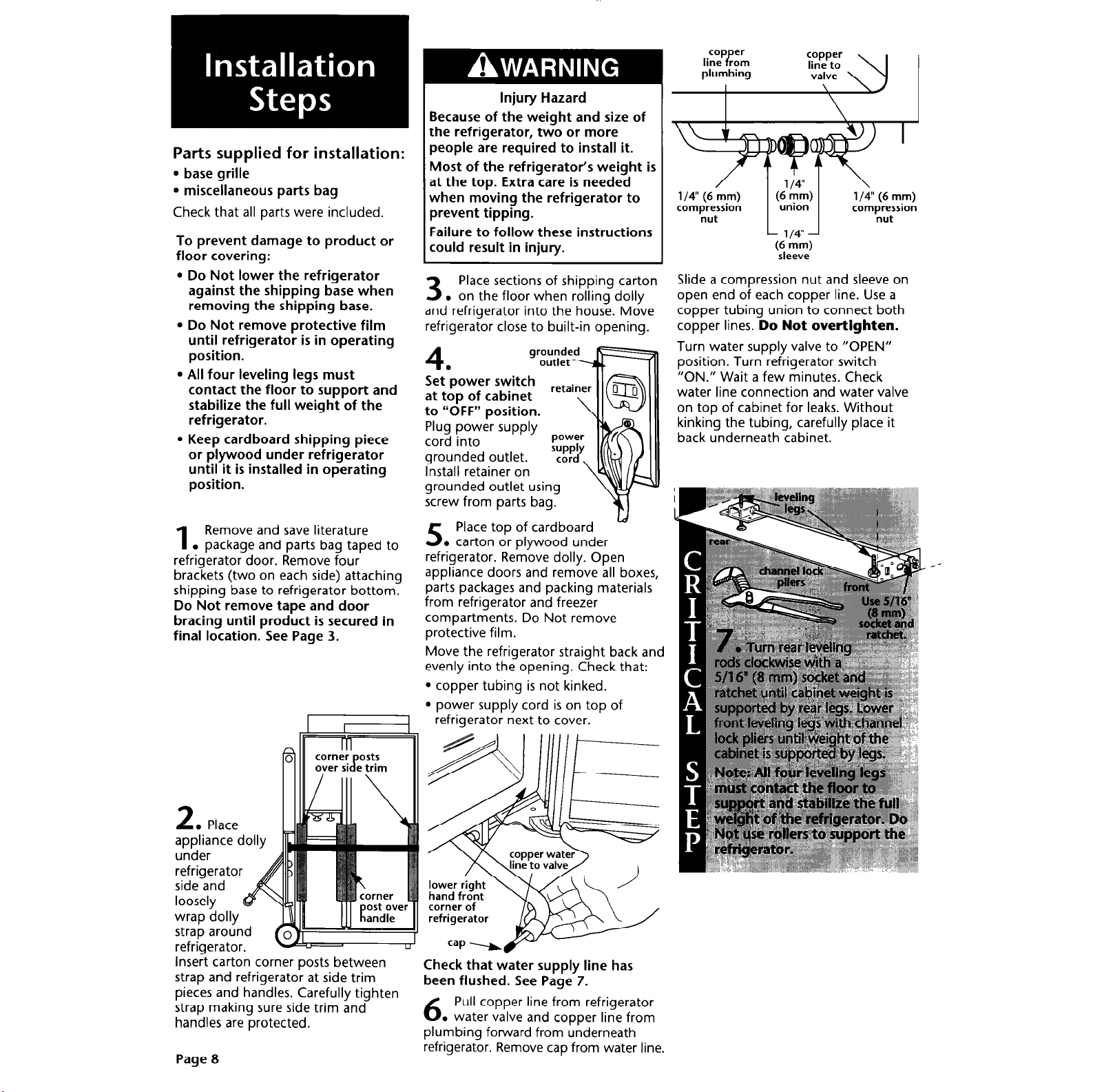
Parts supplied for installation:
l base grille
l miscellaneous parts bag
Check that all parts were included.
To prevent damage to product or
floor covering:
l Do Not lower the refrigerator
against the shipping base when
removing the shipping base.
l Do Not remove protective film
until refrigerator is in operating
position.
l All four leveling legs must
contact the floor to support and
stabilize the full weight of the
refrigerator.
l Keep cardboard shipping piece
or plywood under refrigerator
until it is installed in operating
position.
Remove and save literature
1
. package and parts bag taped to
refrigerator door. Remove four
brackets (two on each side) attaching
shipping base to refrigerator bottom.
Do Not remove tape and door
bracing until product is secured in
final location. See Page 3.
Injury Hazard
Because of the weight and size of
the refrigerator, two or more
people are required to install it.
Most of the refrigerator’s weight is
at the top. Extra care is needed
when moving the refrigerator to
prevent tipping.
Failure to follow these instructions
could result in injury.
Place sections of shipping carton
3
. on the floor when rolling dolly
and refrigerator into the house. Move
refrigerator close to built-in opening.
4
Set’power
at top of cabinet
to “OFF” position.
Plug power supply
cord into
grounded outlet.
Install retainer on
grounded outlet using
screw from parts bag.
Place top of cardboard
5
. carton or plywood under
refrigerator. Remove dolly. Open
appliance doors and remove all boxes,
parts packages and packing materials
from refrigerator and freezer
compartments. Do Not remove
protective film.
Move the refrigerator straight back and
evenly into the opening. Check that:
l
copper tubing is not kinked.
l
power supply cord is on top of
refrigerator next to cover.
ld
compression
nut nut
Slide a compression nut and sleeve on
open end of each copper line. Use a
copper tubing union to connect both
copper lines.
Turn water supply valve to “OPEN”
position. Turn refrigerator switch
“ON.” Wait a few minutes. Check
water line connection and water valve
on top of cabinet for leaks. Without
kinking the tubing, carefully place it
back underneath cabinet.
union
L 1
l/4”
(6
mm)
sleeve
compression
Do Not over-tighten.
L. Place
appliance dolly
under
refrigerator
side and
loosely
wrap dolly
-C--.refrigerator.
Insert carton corner posts between
strap and refrigerator at side trim
pieces and handles. Carefully tighten
strap making sure side trim and
handles are protected.
Page 8
Check that water supply line has
been flushed. See Page 7.
Pull copper line from refrigerator
6
. water valve and copper line from
plumbing forward from underneath
refrigerator. Remove cap from water line.
Page 9
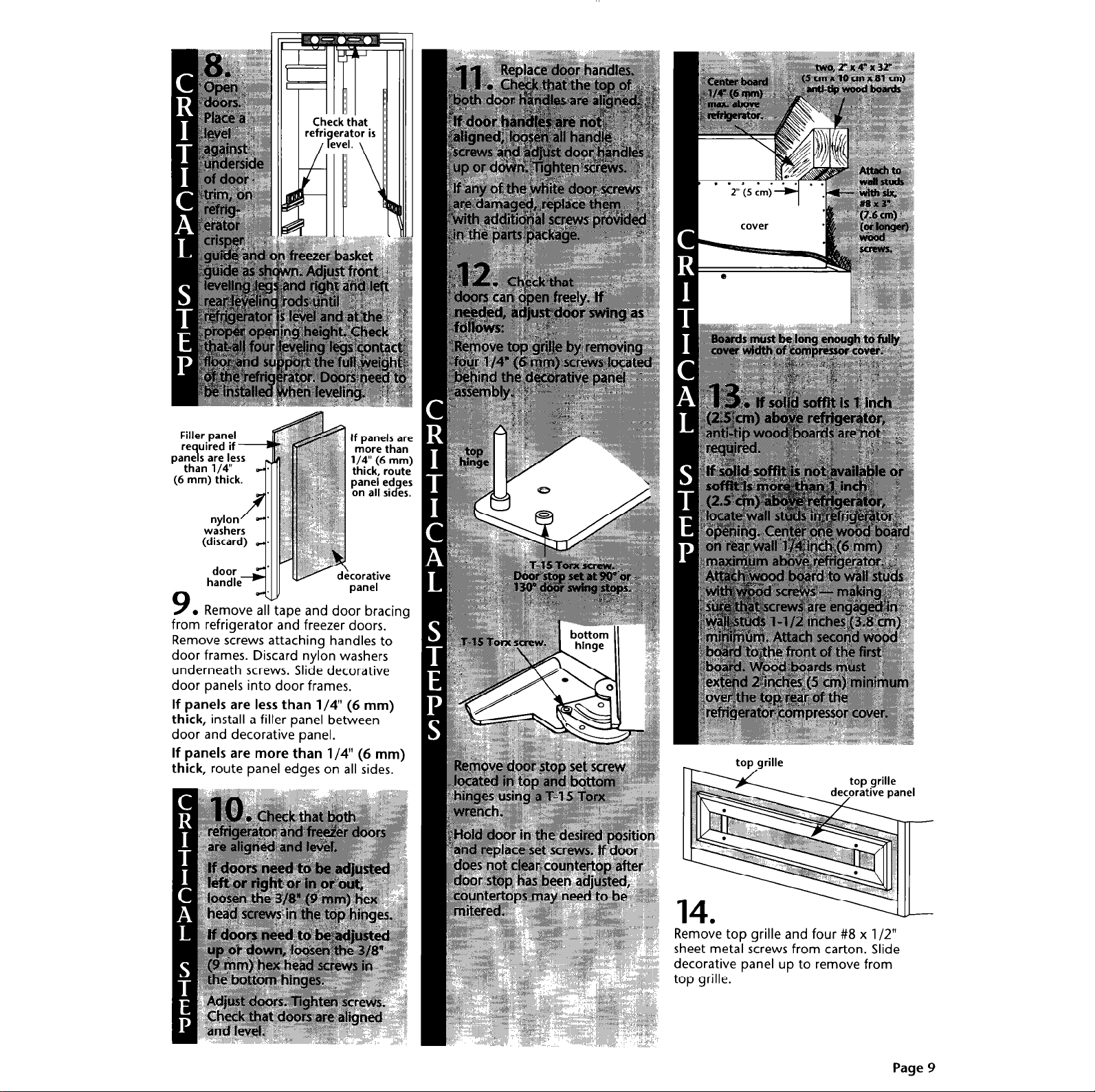
Filler panel
uired if -
If panels are
more than
l/4” (6 mm)
thick, route
paneled es
on all 51 es. 2
n
1
7, Remove all tape and door bracing
from refrigerator and freezer doors.
Remove screws attaching handles to
door frames. Discard nylon washers
underneath screws. Slide decorative
door panels into door frames.
If panels are less than l/4” (6 mm)
thick,
install a filler panel between
door and decorative panel.
If panels are more than l/4” (6 mm)
thick,
route panel edges on all sides.
Remove top grille and four #8 x l/2”
sheet metal screws from carton. Slide
decorative panel up to remove from
top grille.
Page 9
Page 10

Assemble the bottom trim of
. the top grille onto the trim at
15
the top of the cabinet.
top grille
h
I I / \ I I
. screws to attach top grille to
16
the mounting brackets on top of the
cabinet.
mounting brackets
Use the four sheet metal
. If side panels are not used,
19
go to Step 20. if built-in area depth
is
25” (63.5
can be installed inside the side trim
or attached to the outside of the side
trim.
T-T
l Inside side trim piece:
edge of routed side panel into trim
piece. Nail rear edge of panel to
support board.
cm) or more,
Top view
- side panel
side panels
wall
d
Slide front
Top view
\ rear wall
\
support board
- side panel
side trim
door
If built-in area depth is less than
25” (63.5
installation according to site
restrictions. (One method is to install a
support nailer on the built-in opening
rear wall. Drill holes into side trim.
Then attach wood support to trim.
Attach side panel to wood support and
support nailer. Cover wood support
with a matching panel piece.)
cm),
complete side panel
bottom __
grille
top
pan
17
from one side of the decorative panel.
Insert your panel. Reattach side trim
and screws.
18
to reattach to top grille. ’
decor
lel
. Remove screws and side trim
. Slide decorative oanel down
Top view
t
I
24-518”
(62 cm)
max.
l Outside side trim piece:
equally spaced holes into side trim
piece.
Do Not drill into side of
appliance.
to trim piece. Nail front and rear
edges of side panel to support
boards. Cover front support board
with a matching panel piece.
Attach a support board
Drill 6
Open appliance doors and
. remove protective film from
20
door frame. Recheck water
connections at bottom of refrigerator
for leaks.
Attach bottom grille to cabinet with
two screws. Install shelves and bins in
refrigerator and freezer compartments.
Set refrigerator and freezer
21
. compartment controls to the
midpoint between “COLD” and
“COLDEST.” Check that the
compressor is operating properly and
that all five lights are working.
Part No. 2003757
0 1996 KitchenAid.
@ KitchenAid. Registered trademark
of KitchenAid.
DUtcHmenAid”
l-lo
Prepared by KitchenAid, St. Joseph, Michigan 49085 Printed in U.S.A.
APPLIA
Page 11

91 c
:m (
36
PO)
106
cm
(4
2
pd
e
122 cm (48 PO)
Important :
Lire et conserver
ces instructions.
L’installation
nkessite
I’intervention de 2
personnes ou plus.
Important :
l
lnstallateur
instructions d’installation au
propriktaire.
l
Propriktaire
instructions d’installation pour
Gfkrence ultkieure.
l
Conserver
d’installation pour consultation
par I’inspecteur local des
installations Glectriques.
: Remettre les
: Conserver les
ces instructions
t
I
I I
I I I
I I
I I I \ \ \
Piece N” 2003757
Page 12

Risque de blessures
A cause du poids et de la taille du
rbfrigerateur, son installation
I’intervention de deux personnes ou plus.
La plus grande partie du poids du
refrigerateur se trouve & la partie
superieure. Manipuler le refrigerateur
avec prudence lors des dbplacements,
pour qu’il ne bascule pas.
Le non-respect de ces instructions peut
Qtre la cause de blessures.
Conserver la plaque en carton ou en
contreplaque de I’emballage sous le
refrigerateur jusqu’a ce qu’il soit install6 a
sa position de service.
n6cessite
Important :
Respecter les dispositions de tous
les codes et reglements en
vigueur.
C’est a I’installateur qu’incombe la
responsabilite de :
. Respecter les specifications et dimensions
d’installation.
9 Installer le refrigerateur convenablement.
l
Verifier que tout le materiel necessaire i
une installation convenable est disponible:
Tube en cuivre de 6 mm (l/4 po)
avec robinet d’arret
Raccord a compression, 6 mm (l/4 po)
6
vis a bois no 8 x 7,6 cm (3 o)
(il peut Ctre necessaire d’utr user des vis
plus longues)
2 morceaux de bois de 5 cm x 10 cm x
81 cm (2 po x 4 po x 32 po) min.
(voir page 4)
Tournevis - pointe Torx T-15
. Verifier que la resistance du plancher lui
permet de soutenir le poids du
refrigerateur (plus de 272 kg/600 lb), des
panneaux de portes et du contenu.
l
Fournir une prise de courant
convenablement reliee a la terre.
l
Verifier que I’emplacement d’installation
permet I’ouverture de la Porte du
refrigerateur a au moins 90”.
7.
Dimensions du produit
Vue avant
III
Remarque:
La dimension “B” peut @tre augmentee ou
diminuCe de 1,3 cm (l/2 po) en employant
la trousse du panneau decoratif disponible
chez votre marchand.
Pour augmenter: employer la trousse de
panneau (84 po) no 4378788 (garniture
argent) ou 4378789 (garniture blanche).
Pour diminuer: employer la trousse de
panneau (83 po) no 4378786
(garniture argent) ou 4378787
(garniture blanche).
I
ModPIes
avec et sans distributeur
I
E
Voir
remarque.
-“-
(
Vue lath-ale
-c
-
-D-
;*:
::
::
; :
: :
: :
::
::
::
::
1
::
c
: :
::
: :
: :
: :
::
;:
::
::
( 1
F
Vue de dessus
-
i
,
I
l
Les dimensions indiquees corres ondent i la
situation oti les pieds de reglage
depassent de 3 mm (l/8
roulettes. Lorsque les pre s sont totalement deploy&
de 32 mm (1 l/4 po) au-dessous des roulettes,
ajouter 29 mm (1 l/8 po) B cette dimension.
Page 2
-8
e I’aplomb
f
o) au-dessous des
Page 13

Caractbistiques et
dimensions de la cavitk
d’encastrement
Tolkrance de + 3 mm (l/8
po) E
pour toutes les dimension;
Risque de blessures
Faire attention g ce que le
rkfrigkrateur ne bascule pas; la plus
grande partie du poids du
rkfrigerateur se trouve B la partie
supkrieure.
Pour eviter que le rkfrigkrateur ne
bascule en tours de service, installer
un soffite massif ou deux tales en
bois de 5 cm x 10 cm x 81 cm
(2 po x 4 po x 32 po) recouvrant la
largeur du couvercle du
compresseur.
Si le soffite massif est place B plus de
2,5 cm (1 po) au-dessus du
rkfrighrateur, installer deux tales en
bois de 5 cm x 10 cm x 81 cm
(2 po x 4 po x 32 po) sur le mur, B
6 mm (l/4 po) au-dessus du
rkfrigkateur. La surface infkrieure
des tales doit etre B 213 cm (84 po)
du plancher. Les tales en bois
doivent Qtre suffisamment longues
pour recouvrir compl&tement la
largeur du couvercle du
compresseur.
Le non-respect de ces instructions
peut Qtre la cause de blessures.
Le rkfrigkrateur encastrk peut Otre
install6 :
l
en retrait dans I’espace disponible entre
les placards.
l
A I’extrCmitg de la rangCe d’armoires; on
utilise alors un panneau IatCral pour
recouvrir le c&S du rCfrig&ateur.
Choisir l’une des methodes et utiliser les
dimensions indiquCes. Les dimensions
indiquCes laissent un dCgagement de 0 cm -
-
I
o
0
Marquer la
position des
poteaux du ,
colombage surl
le mur arrihe,
B 203-229 cm i
(80-90 po) audessus du sol.
I
Ha
wteur
Installer des supports des
panneaux latkaux (facultatifs)
sur le mur arrke si la
profondeur de la cavitC est de
64
cm (25 po) ou plus.
Emplacement de la canalisation d’arrivke
d’ek
La canalisation d’arrivke
d’eau doit fournir de l’eau
sous une pression de
103-690 kPa (15-l 00
Iblpo’). Effectuer
I’installation
prkliminaire de la
canalisation d’eau avant
d’installer le rkfrigkrateur.
j
I
I
(7
/
Emplacemht de la prise
de courant klectrique
reliCe ir la terre.
Une prise de courant
Clectrique relike a la terre
est nkcessaire.
Largeur -b
18 cm
(7
6,3
(1
3,8
l/2
cm
PO)
PO)
196 cm
(77
PO)
PO)
cm
Trou de 12 mm
(l/2 po) pour le
passage de la
canalisation (a un
emplacement
quelconque dans la
zone ombragke).
Dimensions de la cavitk
Modtile 91 cm (36 po)
Largeur min.
Hauteur min.
Hauteur max.
Profondeur min. 60
90 cm (35 l/2 po)
211~5 cm
215 cm (84 3/4 po)
(83 l/4
cm (23 l/2 po)
GPO) \
Plancher
refrigkrateur, des panneaux de portes et du contenu.
Po) 211,5 cm (83 l/4 po) 211,s cm (83 l/4 PO)
: Le plancher doit pouvoir soutenir le poids du
106 cm (42 po) 122 cm (48 po)
105 cm (41 l/2 po)
215
cm (84 3/4 po)
60 cm (23 l/2 po) 60 cm (23 l/2 po)
120 cm (47 l/2 po)
215 cm (84 3/4 PO)
7--r--t
Page 3
Page 14
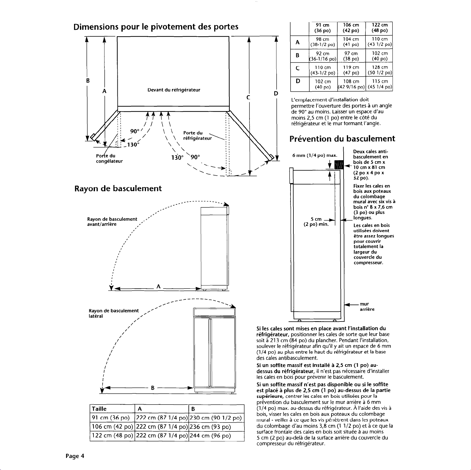
Dimensions pour le pivotement des portes
I A I
Devant du rkfrigkrateur
A
91 cm
(36 PO) (42 PO)
A
B
C
D
L’emplacement d’installation doit
permettre I’ouverture des portes a un angle
de 90” au moins. Laisser un espace d’au
moins 2,5 cm (1 po) entre le c6tC du
refrigerateur et le mur formant I’angle.
98 cm 104 cm
(38-l/2 po) (41 po)
92 cm
(36-l/1 6 po) (38 po)
1lOcm
(43-l/2 po) (47 po)
102 cm
(40 po) (42 9/l 6 po) (45 l/4 po:
106 cm 122 cm
(4 PO)
1lOcm
(43 l/2 po:
97 cm
119cm
108 cm
102 cm
(40 PO)
128 cm
(50 l/2 po:
115 cm
)I
I
congklateur
Rayon de basculement
Rayon de basculement ;*’
avant/arriGre
Rayon de basculement
lateral
I
I
I
I
I
I
I
I
I’
/
/
I/
II
I
I
&-B---D
Taille
91 cm (36
106 cm (42
122 cm (48
IA IB I
po)
po)
po)
I-
,’
,’
,,/’
/
/
222
cm (87 l/4
222
cm (87 l/4
222 cm (87 l/4 po) 244
\ \
po)
230
po)
236 cm (93
:eudi j \\
: :
j :
cm
(90 l/2
cm (96
po)
po)
po)
Pr&ention du basculement
I\ I
6 mm (l/4 po) max.
5 cm
(2 po) min.
Si les tales sont mises en place avant I’installation du
rkfrigkrateur, positionner les tales de sorte que leur base
soit i 213 cm (84 po) du plancher. Pendant I’installation,
soulever le refrigerateur afin qu’il y ait un espace de 6 mm
(1
J4
po) au plus entre le haut du refrigerateur et la base
des tales antibasculement.
Si un soffite massif est install6 i 2,s cm (1 po) au-
dessus du refrigbateur, il n’est pas necessaire d’installer
les tales en bois pour prevenir le basculement.
Si un soffite massif n’est pas disponible ou si le soffite
est pIa& A plus de
supkrieure, centrer les tales en bois utilisees pour la
prevention du basculement sur le mur arriere a 6 mm
(1
J4
po) max. au-dessus du refrigerateur. A I’aide des vis a
bois, visser les tales en bois aux poteaux du colombage
mural - veiller a ce que les vis per&rent dans les poteaux
du colombage d’au moins 3,8 cm (1 l/2 po) et a ce que la
surface frontale des tales en bois soit sit&e a au mains
5 cm (2 po) au-deli de la surface arriere du couvercle du
compresseur du refrigerateur.
2,s
4
cm (1 po) au-dessus de la partie
Deux tales antibasculement en
bois de 5 cm x
*lOcmx81 cm
(2 po x 4 po x
32 PO).
Fixer les tales en
bois aux poteaux
du colombage
mural avec six vis B
bois no 8 x 7,6 cm
(3 po) ou plus
_ longues.
Les tales en bois
utilisees doivent
Ctre assez longues
pour couvrir
totalement la
largeur du
couvercle du
compresseur.
+ mur
arrihe
Page 4
Page 15

1. Ensembles de panneaux
Quatre ensembles de panneaux de portes
en acrylique color@ ou en acier inoxydable
sont disponibles de votre concessionnaire
Panneaux - Numkros des ensembles
2. Panneaux personnalisks
KitchenAid. Utiliser les instructions
d’installation fournies avec chaque
ensemble pour I’installation des panneaux.
Le poids des panneaux personnalisCs
NE doit PAS dkpasser les valeurs
indiqukes.
L’installation de panneaux dont le
poids dkpasse la limite indiquke peut
Ctre la cause de dommages pour le
produit.
REMARQUE : Tolkrance de + 1,5 mm
(l/16 po) pour les dimensions indiqkes.
Les panneaux dont I’Cpaisseur est
supkrieure b 6 mm (l/4 po) doivent faire
I’objet d’un usinage. Lors de I’emploi de
panneaux dkje amincis par usinage,
ajouter 1,s mm (l/16 po) aux dimensions
indiqukes.
Si I’Cpaisseur des panneaux est infhrieure B
6 mm (l/4
remplissage entre les portes et les panneaux
decoratifs.
PO),
installer un panneau de
Poids maximal
Panneaux de portes du
conaClateur (avec
dystributeir)
Poids maximal
combin des
deux
panneaux :
13,s kg
(30 lb)
Panneaux dc
Porte du
congklateur
(sans
distributeur)
Maximum
weight:
30 ounds
(lh kg)
T
E
-Ho
Panneau de Porte
du rkfrigkrateur
Poids maximal :
23 kg (50 lb)
A-
Panneau de la grille su
[poids max. : 4,s kg
Taille A
91 cm
(36 no) (32 318 00)
\ ‘- r-I
122 cm
(48 PO)
*La dimension “6” augmentera ou diminuera de 1,3 cm (1
sont utilises.
82 cm
\-- -I- r-, \- r-,
113cm
(44 3/B
irieure
0 lb)]
8
15cm 36 cm
(6 001 (14 1 I4
1Scm
po) (6 po)
B
B
I n I
C
I
60 cm
DO) 123 7/l 6
~. ,~ -, \-- , - r-, \_ , - r-, \,_ _, r-,
.
49 cm
c1 9 1 /4
60 cm 87 cm
PO) (23 7116 PO) (34 7/l 6
DO) (34 7/l 6 DO)
I
L
F
I I I I
87 cm
J2
po) si les trousses de panneaux decoratifs indiques a la page 2
I c
36 cm
(14 1 I4 001
49 cm 179cm 67 cm
(19 l/4
PO)
I r.
PO)
179cm
(70 7/l 6 DC’
\_ _
(70 7/l 6
L
I u
n
49 cm
(‘0 1 IA nn’
, - r”) (LL J,-l WV,
PO)
(26 l/4
PO)
179rm
isi Zi’6 po)
179cm
(70 7/l 6
1
-
I
PO)
Page 5
Page 16

Vue de I’extrkmitk - c&k poignke du panneau
Panneaux
personnalisk
d’epaisseur supCrieure
A 6 mm (l/4 po) :
Amincir par usinage a la
toupie sur toute la
longueur ou a des
emplacements choisis
du cot6 poignke du
panneau, sur 8,25 cm
(3 l/4 PO>.
8,25 cm
Dimensions pour
I’usinage B la
peripherie des
panneaux
19mm
(314 PO)
min.
Vue latbrale
7
+6mm
(l/4 PO)
max.
poignee
min.
3. Panneaux latkaux
Si le panneau IatCral doit s’engager dans une
garniture IatCrale, et si I’kpaisseur du
panneau IatCral est supkrieure A 6 mm
(l/4 PO), amincir par usinage le bord avant du
panneau pour qu’il puke passer dans la pike
de garniture.
Vue de I’extrCmitC de la piece
de garniture latdrale
6mm
(1
I4
PO)
1,s mm
(l/16 po)
5,s mm
(7/32 po)
1
4mm
(S/32 po)
panneau
Largeur et hauteur :
selon le type
d’installation.
ipaisseur :
Minimum 12 mm (l/2
po) pour empecher le
gauchissement.
panneau
1
tringle de clouage et
support du panneau lateral
10 mm (13/32 po)
panneau lateral
engage dans la piece
de garniture laterale.
- tringle d!aPp?
panneau lateral hors de
la piece de garniture
laterale, et en retrait.
Page 6
4
panneau lateral
hors de la piece
de garniture laterale.
Encoches pour la
plinthe en retrait (le
cas Cchiant).
Determiner la hauteur
\
du refrigerateur
install6 avant de
decouper les
encoches.
. .
prece de garniture laterale
Mode’e (36
91 cm
91 cm 106cm
A
(36 PO)
90 cm
B
(35 l/2
89 cm 104cm
C
(35 PO)
po)
po)
106cm
(42 PO)
(42 PO)
105 cm
(41 l/2
(41 IJo)
po)
122cm
(48 ~0)
122cm
(48 PO)
12Ocm
(47 l/2
119cm
(47 PO)
po)
Page 17

Spkifications de I’alimentation
klectrique
Risque de choc klectrique
Cet appareil doit etre reli6 Blectriquement B
la terre.
Ne pas utiliser une tuyauterie de gaz pour
la liaison & la terre.
Ne pas modifier la fiche de branchement du
cordon d’alimentation Blectrique. Si la
configuration du cordon ne correspond pas
B celle de la prise de courant, faire installer
une prise convenable par un Blectricien
qualifE
Ne pas installer un fusible dans le circuit
de liaison B la terre ou dans le conducteur
neutre.
Ne pas utiliser un fil de rallonge.
Demander & un technicien qualifik de
verifier la qualit de la liaison b la terre.
C’est au client qu’incombe la
responsabilit6 de:
Contacter un Blectricien qualifik pour
I’installation.
Veiller B ce que I’installation Blectrique soit
adequate et conforme au Code national des
installations Blectriques, ANSVNFPA 70 derni&re Edition” ou au Code canadien des
installations Blectriques, C22.1-1982 et
C22.2 No 01982 (ou dernikre edition)*, et B
tous les codes et reglements locaux en
vigueur.
Le non-respect de ces instructions peut
&tre la cause d’un choc Blectrique ou meme
d’un accident mortel.
Si les codes en vigueur le permettent et si un fil
distinct de liaison i la terre est utilisC, on
recommande qu’un Clectricien qualifiP
determine que le conducteur de liaison a la terre
est adCquat.
prise de courant m
3 alvColes, reliee B
fiche de branchement a 3
broches, reliee e la terre
cordon d’aliment
Une prise de courant de 120 V, 60 Hz, CA
seulement, 15 ou 20 A, avec fusible, doit Gtre
disponible. On recommande I’emploi d’un
fusible temporise ou d’un disjoncteur.
d’elect
B la terre
bribe de retenue
la terre, contormement aux dlsposltlons
a
du Code National klectrique, ANSI/NFPA
70 - derniPre edition** ou du Code
canadien des installations klectriques
C22.1-1982 et C22.2 no 01982 (ou
derniitre edition)*, et de tous les codes
locaux et reglements en vigueur.
On peut obtenir un exemplaire des codes
mention&s i I’adresse suwante :
‘Association canadienne de normalisation
178 Rexdale Boulevard
Etobicoke, Ontario M9W 1 R3
l
* National Fire Protection Association
Batterymarch Park
Quincy, Massachusetts, 02269
Spkifications de
I’alimentation en eau
Risque de choc klectrique
II peut exister un rksidu d’eau dans la
canalisation.
II faut que la perceuse Blectrique
utilisf5e soit reli6e B la terre pour
lviter tout risque de choc Blectrique
advenant I’introduction d’eau dans la
perceuse pendant I’utilisation.
Le non-respect de ces instructions
peut Qtre la cause d’un choc
Blectrique ou mgme d’un accident
mortel.
Pour kiter tout dommage B la
propriCtC ou au produit:
l
Utiliser uniquement du tube de
cuivre de l/4 po (6mm) pour
canalisation d’eau.
. Ne pas faire une installation de tube
de
cuivre a un endroit ex
- au-dessous de 32°F IO”C
. Avant de raccorder le tube de cuivre
au rkfrigkrateur, faire couler au
moins 1,9 litre (2 pintes) d’eau B
travers le tube de cuivre pour le
rincer et pour Climiner toute
particule solide prkente dans la
canalisation; rikupkrer I’eau dans un
seau.
l
Ne pas serrer excessivement les
brides au raccord. Le tube de cuivre
s’kcraserait.
l
VPrifier pour rechercher les fuites au
niveau de la bride de branchement.
La canalisation d’eau alimentant le
refriq&ateur doit fournir de l’eau sous une
pres;ion de 103-690 kPa (15-l 00 Ib/po2).
Calcul de la longueur nkessaire de la
section d’un tube en cuivre de 6 mm
(l/4 po) de diam. ext. :
. I
osi! au gel
e
1. Identifier a proximitP du Gfrigerateur une
canalisation d’eau FROIDE verticale de 1,2 cm g
3,2 cm (l/2 po ?I 1 l/4 PO). On peut Cgalement
utiliser une canalisation d’eau FROIDE horizontale
si les instructions de I’etape 4 sont
scrupuleusement observCes.
2. Mesurer la distance entre la canalisation d’eau
froide et le refrigerateur. Ajouter 61 cm (24 po) a
cette dimension.
Pose prkliminaire de la canalisation d’arrivke
d’eau :
3. FERMER le robinet principal d’alimentation.
OUVRIR le robinet le plus proche assez longtemps
pour purger toute l’eau des canalisations.
4. Canalisation d’eau froide verticale : Utiliser une
perceuse electrique reliPe B la terre ou une
perceuse manuelle pour perter un trou de
4,s mm (3/l 6 po) a un emplacement facilement
accessible de la canalisation.
Canalisation d’eau froide horizontale
une perceuse Clectrique reliCe a la terre ou une
perceuse manuelle pour perter un trou de
4,5 mm (3/l 6 po) dans la partie supCrieure de la
canalisation. Ainsi, des sediments ne
s’accumuleront pas dans le robinet de prise en
charge.
5. Placer le joint sur le trou per& de la canalisation
Faire tourner la manette du robinet de prise en
charge dans le sens horaire pour faire dCpasser la
pointe percante d’un maximum de 4,s mm
(3/l 6 PO). Aligner la pointe percante avec le trou
per& dans la canalisation. Placer les deux moities
de la bride de fixation du robinet de
prise en charge contre la
canalisation. Faire tourner la
manette du robinet dans le sens
horaire jusqu’i ce que la pointe
percante pCnPtre dans le trou de
la canalisation et soit fermement
en place. Le robinet de prise en
charge n’est pas a la
position de fermeture.
Serrer I’@crou autour de la
tige de commande. Serrer
uniformement et fermement les vis
de bridage, afin que le joint Ptablisse
une connexion ktanche. Ne
pas serrer
: Utiliser
excessivement; le tube en cuivre pourrait
s’kraser.
6. Veiller a ce que les deux extr@mit& du tube en
cuivre soient coupCes a I’equerre. Enfiler I’Ccrou de
compression et la virole sur le tube en cuivre.
Enfoncer complPtement I’extrPmite du tube en
cuivre dans I’ouverture du robinet. Serrer I’Ccrou
de compression sur le raccord avec une cl6 2
molette. Ne
7. Ouvrir le robinet principal d’alimentation.
Inspecter pour rechercher les fuites. Faire tourner
la manette du robinet de prise en charge dans le
sens antihoraire et laisser de l’eau s’&ouler .?I
travers le tube en
cuivre dans un seau. &ou de
Faire tourner la
manette dans le
sens horaire pour
interrompre
I’Pcoulement de l’eau a
travers le tube en cuivre.
8. Acheminer le tube en cuivre jusqu’a la zone
d/installation du rPfrig&ateur.
9. Enfiler I’&rou de compression et la virole
canalisation d’eau. Visser I’Ccrou sur le raccord et
serrer. Ne
pas serrer excessivement.
compression cuivre
,
virole
pas serrer excessivement.
tube en
I
raccord
sur la
Page 7
Page 18

Pikes fournies pour
I’installation :
l
grille de ventilation basse
l
Sachet de pieces
Verifier que toutes les pieces sont presentes.
S’assurer que toutes les pikes sont
incluses:
Pour kiter tout dommage qui affectera le
produit ou le revetement de sol:
. Ne pas baisser le refrigerateur contre la
base utilisee pour le transport lors de
I’enlevement de cette base.
l
Ne pas retirer la pellicule de protection
avant que le refrrgerateur soit en
position de
l
Veiller a ce que les quatre pieds soient en
contact avec le sol, supportent tout le
poids du refrigerateur et le stabilisent.
l
Laisser le refrigerateur sur une feuille de
carton ou de contreplaque jus u’a ce
qu’il soit install6 a sa position
Enlever le sachet de documents et le
1
. sachet de pieces fixes sur la Porte du
refrigerateur; conserver ces articles en lieu sur.
&er les quatre brides (deux de chaque cot@)
fixant la base utilisee pour le transport en bas
du refrigerateur.
adhesifs et entretoises qui immobilisent les
portes avant que le refrigerateur ait ete
solidement installe a la position de service
finale. Voir page 3.
2
. Mettre le
chariot sous le tote
du refrigerateur et
arrimer le
service.
a e service.
Ne pas 6ter les rubans
Risque de blessures
A cause du poids et de la taille du
rkfrigkrateur, son installation
nkcessite I’intervention de deux
personnes ou plus.
La plus grande pat-tie du poids du
rkfrighrateur se trouve B la partie
supkrieure. Manipuler le refrigkrateur
avec prudence lors des dtSplacements,
pour qu’il ne bascule pas.
Le non-respect de ces instructions
peut 6tre la cause de blessures.
Avant de deplacer le refrigerateur sur
3
. le plancher de la maison, sur un
chariot, placer sur le plancher les sections
de I’emballage de carton. Approcher le
refrigerateur pres de I’ouverture de
I’encastrement ou il sera installe.
4
. Pousser le
commutateur
d’alimentation sit&
en haut de la caisse a bride de
la position d’arret
(OFF).
Brancher le
cordon d’alimentation
sur une prise de
courant Clectrique
reliee a la terre. Fixer la bride d
retenue sur la prise de courant
avec la vis qu’on trouve dans le
sachet de pieces.
Mettre une plaque en contreplaque
5
. ou en carton sous le refrigerateur.
Retirer le chariot de manutention. Ouvrir
les portes de I’appareil et 6ter toutes les
boites, les sachets de pieces et les
materiaux d’emballage qu’on trouve dans
le compartiment de refrigeration et le
compartiment de congelation. Ne
la pellicule protectrice.
lnserer le refrigerateur dans I’ouverture
d’encastrement, en ligne droite et
uniformement. Verifier que :
. le tube en cuivre n’est pas deform&
l
le cordon d’alimentation Clectrique est au
sommet du refrigerateur, pres du
couvercle.
prise de
courant reliee
pas Bter
canalisation en
cuivre reliCe au
circuit de
plomberie de la -
maison ,
/
Ccrou de
compression
de6mm
(114 PO>
I
Enfiler un Ccrou de compression et sa virole
sur I’extremite libre de chaque canalisation
de cuivre. Utiliser un raccord droit pour
tubes de cuivre pour raccorder les deux
canalisations de cuivre.
excessivement.
Ouvrir le robinet d’arrivee d’eau (position
OPEN). Placer le commutateur
d’alimentation electrique du refrigerateur i
la position de marche (ON). Attendre
quelques minutes. Inspecter la connexion
de la canalisation d’eau et le robinet
d’arrivee d’eau au sommet de la caisse pour
identifier les fuites Cventuelles. Reinserer la
canalisation de cuivre sous le refrigerateur,
en veillant a ne pas I’ecraser.
canalisation en
cuivre, vers le
robinet
\
raccord
droit de
6mm
(114
PO)
1 !
vwole de
6mm
(114 PO)
Ne pas serrer
\
icrou de
compression
de6mm
(1 I4 PO)
trop serrer.
lnserer les cornieres
en carton pour
proteger les garnitures laterales et les poignees
entre la sangle et le refrigerateur. Serrer
prudemment la sangle en verifiant que les
pieces de garniture laterales et les poignees
sont protegees.
Page 8
f
Verifier que la canalisation d’arrivee
d’eau a Cti purgee. Voir page 7.
Extraire la canalisation de cuivre du
. robinet d’alimentation en eau du
6
refrigerateur, et tirer vers I’avant pardessous le refrigerateur la canalisation de
cuivre reliee au circuit de plomberie.
Enlever le bouchon du conduit d’eau.
Page 19

Panneau de
remplissage
nkcessaire si I’Cpaisseur du
panneau
dkcoratif est
infkrieure B
6 mm (l/4 PO).
rondelles
de nylon
(A jeter)
. her tous
9
entretoises des portes du refrigerateur et
du congelateur. Oter les vis fixant les
poignees aux cadres de portes. Enfiler les
panneaux decoratifs des portes dans les
cadres de portes.
Si I’kpaisseur du panneau dkcoratif est
infhieure
panneau de remplissage entre la Porte et
le panneau decoratif.
Si I’kpaisseur du panneau dkoratif est
supkrieure B 6 mm (l/4 PO), amincir tous
les bords oar usinaqe a la toupie.
/
poigrkede Porte -
ir 6 mm (l/4
4
les
rubans
bkcoratif
adhesifs et
PO),
installer un
du panneau
dkcoratif est
supirieure B
6mm
(l/4
PO),
nincir tous
les bords par
usinage h la
Vupie.
beau
fur
h /
grille supkrieure
szn;eau dkcoratif
14 .
Retirer de I’emballage la grille superieure et
les quatre vis a tolerie r-r” 8 x l/2 po.
Pousser le panneau decoratif vers le haut
pour enlever la grille superieure.
Page 9
Page 20

Placer la garniture infkrieure de la
. grille superieure en
15
chevauchement sur la garniture au
sommet du placard.
grille.
superleure
.
16
les brides de montage
placard.
brides de montage
Utiliser les quatre vis a talerie
. pqur fixer la grille supkieure sur
panneau dkoratif
de I? yille
superleure
au
sommet du
. Si aucun panneau IatCral n’est
19
utilisk, passer B I’CEape 20.
Si la profondeur de la cavitC
d’encastrement est de 63,s cm (25 po)
ou plus, on peut engager
latkaux a I’intCrieur de la garniture
lat&ale, ou les fixer i I’extCrieur de la
garniture laterale.
les panneaux
Vue de dessus
A A
garniture laterale
Porte
L
l
Pike de garniture ladrale interne :
Enfiler le bord avant aminci du panneau
lateral dans la pike de garniture. Clouer
le bord arriPre du panneau sur la
planchette d’appui.
Vue de dessus
6Lcm I
Si la profondeur de la cavid d’encastrement
est infikieure
I’installation des panneaux IatCraux en tenant
compte des restrictions imposkes par les
caractkistiques du site d’installation. (Une
mPthode consiste a installer une planchette de
clouage et d’appui sur le mur arriPre de la cavite
d’encastrement. Perter des trous dans la
garniture laterale. Fixer ensuite la planchette
d’appui a la garniture. Fixer le panneau IatCral
sur la planchette d’appui et la planchette de
clouage. Recouvrir la planchette d’appui avec un
morceau de panneau assorti.)
?I 63,s
Y l//l
I
cm
(25
grille de
PO),
executer
. Oter les vis et la garniture
17
IatCrale sur un c6te du panneau dkoratif.
InsCrer le nouveau panneau. Reinstaller la
garniture laterale et les vis.
18
. Laisser descendre le panneau
dkoratif pour fixer de nouveab la grille
supkrieure.
Vue de dessus
lanchette d’appui
l
Pike de garniture latkrale externe :
Perter 6 trous Cquidistants dans la pike
de garniture IatCrale. Ne
dans le c6tC de I’appareil.
planchette d’appui sur la piece de
garniture. Clouer les bords avant et
arriere du panneau lateral sur les
planchettes d’appui. Recouvrir la face
avant des planchettes d’appui avec un
morceau de panneau assorti.
pas perter
Fixer une
Ouvrir les portes de I’appareil et
. Bter la pellicule protectrice de
20
I’encadrement des portes. Inspecter de nouveau
les raccords de connexion de tuyauterie situ&
en bas du rgfrigkateur pour rechercher les
fuites.
Fixer la grille de ventilation de la base avec deux
vis. Installer les ktageres et caissons dans les
compartiments de rkfrigeration et de
congklation.
RCgler les thermostats du
. GfrigGrateur et du congelateur au
21
point mCdian entre les rep&es FROID et TRES
FROID. Verifier que le compresseur et les cinq
lampes fonctionnent normalement.
Piece N” 2003757
0 1996 KitchenAid
8 KitchenAid. Marque dCpos@e de
KitchenAid.
PrCparC par KitchenAid, St. Joseph, Michigan 49085
ImprimC aux C.-U.
Page 21

36 pulg. [91 cm]
42 pulg. [106 cm]
y 48 pulg. [122 cm]
Refrigeradores
Empotrados
Importante :
Leer y guardar
estas instrucciones.
Se requiere 2 0 rnk
personas para
instalar.
Importante :
l
lnstalador
con el propietaro.
: Dejar instrucciones
l
Propietario
instrucciones para referencia en
el futuro.
l
Guarde
instalacih para uso del inspector
ektrico.
: Cuardar
estas instrucciones de
Pieza No. 2003757
Page 22

Peligro de Heridas
Por el peso y tamafio del refrigerador,
se requiere dos o mas personas para
su instalacion.
La mayor parte del peso del
refrigerador se encuentra en la
section superior. Se requiere de
cuidado especial al mover el
refrigerador, para prevenir su
inclination.
La falta de atencion a estas
instrucciones pueden causan
heridas.
Mantener el carton de empaque o pieza
de plywood debajo del refrigerador
hasta que se encuentre en su sitio
permanente.
Obseravar todas las
disposiciones y regulaciones
del case.
Es su responsabilidad:
l
Observar las disposiciones sobre
instalacion y dimensiones.
l
lnstalar el refrigerador en forma correcta.
l
Verificar que dispone de 10s siguientes
materiales necesarios para una
instalacion correcta:
tuberia de cobre de l/4 pulg. [6
mm] con vilvula de cierre
accesorio de compresion de l/4
pulg. [6 mm]
6 tornillos par madera #8 x 3 pulg.
[7,6
cm1
[es posible que requiera tornillos
m6s largos]
2 tiras de madera de 2 pulg. x 4
pulg. x [S cm x 10 cm x 81 cm] min.
[ver Pbgina]
T-15 Tornillo Torx
l
Confirmar que el piso puede soportar un
refrigerador de un peso [mayor a 600
lbs./272 kg.], paneles de puertas y su
contenido interior.
l
Proveer un enchufe electrico con su
debida tierra.
l
Verificar que el lugar permite la apertura
de la puerta del refrigerador por lo
menos 90”.
* Las dimensiones indicadas surten efecto
para 10s niveladores extendidos l/8 pulg.
[3 mm] debajo de 10s rodillos. Para
niveladores extendidos l-1/4 pulg. [32 mm]
debajo de 10s rodillos, aumentar l-1/8 pulg.
[29 mm’ a esta dimensi6n.
Pggina 2
DIMENSIONES
Vista Frontal
Nota:
La dimension “B” puede ser
aumentada o disminuida l/2 pulg.
(1,3 cm) usando 10s Juegos de Rejilla
disponibles de su distribuidor.
Para aumentar: use el Juego de
Rejilla de “84 pulgadas” N” 4378788
(Moldura Plateada) o 4378789
(Moldura Blanca).
Para disminuir: use el Juego de
Rejilla de “83 pulgadas” N” 4378786
(Moldura Plateada) o 4378787
(Moldura Blanca).
Modelos Con Expendedor
1
36
pulg (91 cm) I42 pulg (106 cm)
A j 36 pulq (91 cm) j 42 pulq (106 cm)
B
83-5/8 pulg (212 cm)* 83-5/8 pulg (212 cm)* 83-5/8 pulg (212 cm)*
C
25-l/8 pulg (64 cm)
D
23-l /2 pulg (60 cm)
E
3-l /2 pulg (9 cm)* 3-l/2 pulg (9 cm)*
F
83-l /8 pulg (211 cm)* 83-l /8 pulg (211 cm)* 83-l /8 pulg (211 cm)*
G
24 pulq (61 cm) 24 pulq (61 cm)
H
35 pulg (89 cm)
I
25 pulg (63.5 cm) 25 pulg (63.5 cm)
25-l /8 pulg (64 cm)
23-l /2 pulg (60 cm)
41 pulg (104 cm)
8
Ver
Nota.
Vista Lateral
-c
-
-
-D-
:
‘a
:n
::
::
::
::
::
; :
: :
: :
: :
: :
::
::
: :
: :
: :
: :
: :
ii
I
-
I,
Vista Superior
148 pulg (122 cm)
148 pulq (122 cm)
25-l /8 pulg (64 cm)
23-l /2 pulg (60 cm)
3-l/2 pulg (9 cm)*
24 pulq (61 cm)
47 pulg (119 cm)
25 pulg (63.5 cm)
Page 23

DIMENSIONES Y
KJ#UM;ENTOS PARA
Todas las dimensiones + l/8
pulg. [3 mm]
Peligro de heridas/Dafios
a la propiedad
Se debe poner atenci6n en todo
moment0 para evitar que el
refrigerador se incline, puesto que la
parte superior soporta la mayor parte
del peso.
un sofito o dos de 2 pulg. x 4 pulg. x
32 pulg. [5 cm x 10 cm x 81 cm] de
madera s6lida para cubrir el ancho
de la tapa del compresor para
prevenir inclinackn durante el uso.
Si el sofito s6lido sobresale m8s de
1 pulg. [2.5 cm] encima del
refrigerador,
instalar dos tiras de madera de 2
pulg. x 4 pulg. x 32 pulg. [5 cm x 10
cm x 81 cm] en la pared, 114 pulg.
[6 mm] sobre la tapa del refrigerador.
La superficie inferior de las tiras de
madera debe permanecer 84
pulgadas [213 cm] del piso. Las tiras
de madera deben ser lo
suficientemente
ancho de la tapa del compresor.
La falta de observancia a estas
instrucciones puede causar heridas
o daiios a la propiedad.
El refrigerador empotrado puede
instalarse:
l
dentro de la cavidad de 10s gabinetes
l
al final de 10s gabinetes utilizando un
panel lateral para cubrir el lado del
refrigerador.
Elija un metodo y utilice las dimensiones
adjuntas. Estas dimensiones permiten una
6rea libre de 0 pulg. [0 cm].
se requiere entonces
largos para cubrir el
-
II
I I Marque el
[ j sitio de la
I I columna en I I
! I la oared
I I posterior
’ ’ 80 - 90 pulg. ’ ’
T203-229
besde el pi&.
bra
lnstalar el soporte del
panel lateral [optional]
en la pared posterior si la
apertura Gene una
profundidad mayor de
25 pulg. [64 cm] o m6s.
PAncho
Tuberia de
agua debe
disponer de una
presi6n de 15-l 00
psi [103-690 kPa].
Efectuar instalacih (3.8 cm)
de la tuberia de
agua antes ae
instalar el
refrigerador
I
5 oula (12.5 cm1
, ,
II
! !
I I
cm1
/
Enchufe elktrico con
tierra
Se requiere un enchufe
ektrico con tierra
Sefial de tuberia de agua
l-l/2
pulg
7 pulg
Pu’g
‘6.3 cm)
Ranura para
plomeria de
II
l/2 pulg. [12 mm]
puede ser situada
en cualquier lugar
- dentro del irea
sombreada.
I /
/
I
Dimensiones de apertura
Modelo
Ancho min.
Altura min.
Altura max.
Profundidad min.
36 pulg (91 cm)
351/2pulg (90crn)
83-l/4 pulg (211.5 cm) 83-l/4 pulg (211.5 cm)
84-3/4
23-l /2 pulg (60 cm)
pulg (215 cm)
I * I II I
1 r
I
i
/
i
Piso: Debe soportar el refrigerador,
contenido y puertas.
I
!
42 pulg (106 cm
41 -i/2-pulg
84-3/4 pulg (215 cm)
23-l /2 pulg (60 cm)
/ : \
1)
(105
cm)
1 (33 cm)-
i
I
48 pulg (122 cm)
47-l /2 pulg (120 cm)
83-l/4 pulg (211.5 cm)
84-3/4 pulg (215 cm)
23-l /2 pulq (60 cm)
L
\ \ \
PLgina 3
Page 24

Dimensick de Puet-tas
B
(
Frente del Refrigerador
A
Puerta del
congelador
Angulo de inclinacibn
Angulo de inclination _----Adelantelatras _*-*
I’
#’
I
I’
I’
1’
:
:
vc
,’
,’
#’
a’
I
I
A
.------------
.-
36
pulg 36 pulg
91 cm 91 cm
38-l/2 pulg
A
(98
cm)
36-l/1 6 pulg 38 pulg
B
(92
cm)
43-l/2 pulg 47 pulg
’ (1lOcm)
D
4o
Pub
(102 cm)
La instalacih permanente debe permitir
un 6ngulo de apertura para las puertas de
minim0 90”. Dejar un espacio minim0 de
1 pulg. [2.5 cm] entre la pared lateral del
refrigerador y la pared esquinera.
42 pulg
42
pulg
106 cm 106 cm 122 cm 122 cm
41 pulg
(104 cm) (110 cm) (110 cm)
(97
cm)
(119 cm)
42-V/1 6 pulg 45-l/4 pulg 45-l/4 pulg
(108 cm) (115 cm) (115 cm)
48 P+J
48 pu’g
43-l /2 pulg 43-l /2 pulg
40
pulg
40
pulg
(102 cm) (102 cm)
50-l /2 pulg 50-l /2 pulg
(128 cm) (128 cm)
Preventivo de inclinacibn
l/4 [6 mm] max.
2
pulg
,5 cm) min.
DOS tiras de
madera para
* prevenir la
inclination de
2
pulg. x 4 pulg.
x 32 pulg. [S cm x
10cm x81 cm].
Fijar a las
columnas
mediante seis
tornillo para
- madera #8 x 3
pulg. [76 mm]
[o m6s largos].
Las tiras de
madera deben
ser
suficientemente
largas para cubrir
completamente
el ancho de la
tapa del
compresor.
Angulo de inclination
Lateral
I
J-B-
1 Dimensih
36 pulg (91 cm)
42 pulg (106 cm)
48 pulg (122 cm)
Pigina 4
------------.
/0r
//’
/
/
I
I
I
87-l /4
87-l/4 pulg (222 cm) 93 pulg (236 cm)
87-l /4 pulg (222 cm) 96 pulg (244 cm)
A
pulg (222 cm) 90-l /2 pulg (230 cm)
1 B
+ Pared
11
il
Si se coloca
refrigerador,
inferior de las mismas se encuentren a 84 pulg. [213 cm]
desde el piso. Durante el proceso de instalacion, levante el
refrigerador hasta dejar un espacio maxim0 de l/4 pulg. [6
mm] entre la parte superior del refrigerador y la supetficie
inferior de las tiras de madera.
Si se encuentra un sofito solid0 de 1 pulg. [2.5 cm] sobre
el refrigerador,
la inclination del refrigerador.
Si no existe un sofito solido, o si el sofito es mayor a 1
pulg. [2.5 cm] sobre la cubierta,
en la pared trasera a l/4 pulg. [6 mm] maxim0 sobre el
refrigerador. Fije las tiras a las columnas de la pared
I
mediante tornillos para madera, verificando que 10s tornillos
se encuentran dentro de las columnas por lo menos l-l /2
pulg. [3.8 cm], y que las tiras de madera sobrepasan por lo
menos 2 pulg. [5 cm] sobre la section superior del area
posterior de la cubierta del compresor del refrigerador.
. . . .
las
twas de madera ante
sittie las tiras de tal manera que la supetficie
no se requiere tiras de madera para prevenir
-I
1 instalar el
is dc
centre las tiras de madera
trasera
Page 25

Nlimero del juego de paneles
Modelo Sin expendedor
1. Juegos de Paneles
Su distribuidor KitchenAid dispone de
cuatro juegos de paneles acrilicos a color
acero inoxidable para puertas y la rejilla
Con expendedor
superior. Siga 10s pasos indicados en las
instrucciones de 10s paneles su instalacion.
0
Tamaiio
Blanc0
Negro
Almendra
Acero lnoxidablel 4318641
36 Pub (91 cm) 42 pulg (106 cm) 48 pulg (122 cm) 36 pulg (91 cm) 42 pulg (106 cm)
4318635 4318636
4318632 4318633
4318638 4318639
14318642 14318643
2. Paneles a medida
Daiio al product0
El peso de 10s paneles fabricados
a medida NO DEBE EXCEDER 10s pesos
indicados.
El sobrepeso de 10s paneles puede
causar daiios al producto.
NOTA: Las dimensiones indicadas
permiten una
tolerancia de +- l/16 pulg. [1.5 mm].
Paneles de m&s de l/4 pulq. [6 mm]
deben tupirse. Si se utilha paneles
tupidos, aumente l/16 pulg. [1.5 cm] a
las dimensiones indicadas.
Si 10s paneles son de un grosor inferior
a l/4 pulg. [6 mm], instale un panel
relleno entre las puertas y 10s paneles
decorativos.
Si 10s paneles son de un grosor mayor a
l/4 pulg.
filos del panel, en todos sus ‘ados.
[6
mm],
pase el tupi sobre 10s
- .
de
4318637
4318634
4318640
e---c-1
I
Peso miximo
combinado
de
10s dos
aneles:
0 libras
P
[13.5 kg]
!
Panel de puerta del
congelador
[sin expendedor]
Peso m6ximo
combinado
de
‘OS dos
riE
[13.5 kg]
:
D
1
4378650
4378653
4378656
14378659
Paneles de las
puertas del
con elador
con
P
expendedor]
Peso
mbximo:
30 libras
[13.5 kg]
4378651
4378654
4378657
14378660
-HH
48 pulg (122 cm)
4378652
4378655
4378658
( 4378661
Panel de puerta
del refrigerador
Peso mdximo:
50 libras
[23 kg1
I
r
I
A-
Panel superior de la rejilla [peso miximo:
10 lbs/4.5 kg]
Tamaiio
36 pulg
(91 cm)
42
pulg
Cl 06 cm)
* La dimension “6” aumentara o disminuira l/2 pulgada (1,3 cm) si se usan 10s juegos de rejillas indicados en la p6gina 2.
A
32-3/8 pulg 6 pulg
(82
cm)
38.3/8 pulg
(97
cm)
44-3/8 pulg
(113 cm)
B
(15 cm) (36 cm)
(4!%1) (43 cm)
,-
C D E F
14-l /4 pulg 2&ylmy pulg :B”;;/lmT pulg &Wpulg 70-7/l 6 pulg $l;;pulg :,o;;/;;@g
16-314 pulg 23-7/l 6 pulg 34-7/l 6 pulg 16-3/4 pulg 70-7/l 6 pulg 22-314 pulg
19-l /4 pulg 23-7/l 6 pulg 34-7/l 6 pulg 1 V-l /4 pulg
(49
cm)
(60
(60
cm)
cm)
(87
(87
cm)
cm)
(43
cm) (179 cm)
(49 cm)
G
(179 cm)
70-7/l 6 pulg 26-l /4 pulg 70-7/l 6 pulg
(179 cm)
H I
(58
cm)
(67
cm) (179 cm)
,:o;;/;M~ulg
r
-
Phgina 5
Page 26

Cotte del filo del panel lado de la manija
Paneles a medida con un
rosor mayor a l/4 pulg.
6
mm]:
9
Pasar el tupi sobre la
totalidad
del lar o o sobre keas
especi icas 9
de 10s paneles del lado de la
manija
3-l/4 pulg. [8.25 cm]
3-l/4 pulg
Dimensiones para
tupir 10s filos
del panel
314
pul
(19 mm
min.
Panel
s
Corte lateral
t
l/4
(6
mm) max.
pulg
3. Paneles laterales
Si el panel lateral se instala
dentro de la moldura lateral y si
el panel tiene un grosor mayor a
l/4 pulg. [6 mm], pase el tupi sobre
el filo frontal del panel para fijar la moldura.
Corte del filo del panel latera
1/4pul
1/16pul j
(1.5 mm
7132
(5.5 mm
Moldura interior
del panel lateral
+
(6
mm
s
3
pul
s
t
+
3
13/32 pulg (10 mm)
Moldura exterior
del panel lateral
Dimensiones para
tupir
Ancho y altura
depende del tipo
de instalacih
Grosor
l/2 pulg [12 mm]
minim0 para
prevenir
deformidades
Ranura para el
list& del z&al0
[si se desea] \
Determinar la altura
antes
de efectuar 10s
tortes
Moldura exterior ahuecada
Pigina 6
I
del panel lateral
Tira de soporte
\-
Corte lateral
Mode’o
A
a
C
pulg
pulg
48 pdg
(122 cm)
48 pdg
36
pulg
(91
36
pulg
(91
35-l/2 pulg 41-l /2 pulg 47-l/2 pulg
(90 cm)
35 pulg
(a9 cm)
42
cm)
(106 cm)
42
(106 cm) (122 cm)
cm)
(105 cm) (120 cm)
41 pulg 47 pulg
(104 cm) (119 cm)
Page 27

Conexiones Ektricas
-
Riesgo de Choque Electrico
Este artefacto debe ser puesto a
tierra.
No poner a tierra en una tuberfa del
gas.
No modifique el enchufe del cord&
electrico. Si no calza en el
tomacorriente, haga instalar un
tomacorriente apropiado por un
electricista calificado.
No use un fusible en el circuit0 de
puesta a tierra 0 neutro.
No use un cordon de extensibn.
Consulte con un electricista
calificado para asegurarse de que
este artefacto este debidamente
puesto a tierra.
Es responsabilidad del cliente:
Ponerse en contact0 con un
electricista calificado.
Asegurarse de que la instalacion
electrica sea adecuada y de acuerdo
con la tiltima edition” ANSVNFPA 70
del C6digo National de Electricidad o
con el Codigo de Electricidad
Canadiense, C22.1-1902 y C22.2 No.
01982 (o la ultima edition)’ y con
todos 10s codigos y reglamentos
locales.
El incumplimiento de estas
instrucciones puede ocasionar la
muerte o choque electrico.
Si las normas lo permiten, y si se utiliza
un cagael separado coma tierra, se
recomienda que un electricista
calificado determine la conezi6n de
tierra correcta.
Caja de pared con tierra
de enchufe triple\
EnchufF triple
con tlerra m
1
Alambre
ektrico
4
-.. . .
1 ermmal
de tierra
5
9
Reienedor
Se requiere una fuente eletrica de 120
voltios, 60 Hz, CA solamente, con fusible
de 15 o 20 amperios. Un fusible de
tiempo diferido es recomendable. Es
tambien recomendable que un circuit0
separado sea provisto para este artefacto.
Este artefacto esta equipado con un
cordon para corriente con enchufe de tres
puntas para puesta a tierra. Para
minimizar el peligro de choque electrico,
el cordon debe estar enchufado a un
receptaculo de pared puesto a tierra, de
acuerdo con el Codigo National de
Electricidad, ANSI/NFA 70 - ultima
edition *, y todos 10s c6digos y
ordenanzas locales.
Copias del estandar listado pueden ser
obtenidos en:
* Canadian Standard Association
178 Rexdale Boulevard
Etobicoke, Ontario M9W 1 R3
l
* National Fire Protection Association
Batterymarch Park
Quincy, Massachussetts 02269
Requerimiento para el
Suministro de Agua
Riesgo de Choque Electrico
Puede quedar agua en la tuberfa.
El taladro electrico debe ser puesto a
tierra para evitar choque grave o letal
si hay agua en la tuberfa y Bsta entra
al taladro durante el uso.
El incumplimiento de esta advertencia
puede causar la muette o choque
electrico.
Use solamente tuberia de cobre para
suministro de agua de l/4” (6mm)
l
No use tuberia de cobre en zonas
donde la temperatura sea menor
que 32°F (O”)
l
Antes de unir la tuberia de cobre al
refrigerador, haga correr por lo
menos 2 cuartos (1.9L) de agua por
la tuberia de cobre a un balde para
limpiar la impurezas en la tuberia de
agua.
l
No ajuste en forma excesiva la
abrazadera o casquillo. Esto puede
machacar la tuberia.
l
Controle que no haya perdidas
alrededor de la montura de la
virlvula.
La tuberia de suministro de agua al
refrigerador debe proveer 15-l 00 psi
(103 - 690 kPa) de presion.
Para calcular la longitud de tuberia de
cobre de D.E. l/4” (6mm) necesitada:
1. Localice la tuberia vertical de agua fria de
l/2” (1.2cm) o l-1 /4” (3.2cm) mas cerca del
refrigerador. Una tuberia horizontal de agua fria
puede ser usada, si se sigue con cuidado las
direcciones en el paso 4.
2. Mida la distancia de la tuberia de agua fria al
refrigerador. Agregue 24” (61 cm) a esta
medida.
Para pre-instalar la entrada de agua :
3. Cierre el suministro de agua. Abra el grifo
mas cercano durante el tiempo suficiente para
vaciar la tuberia de agua.
4. Tuberia de agua fria vertical:
taladro electrico puesto a tierra, o un taladro de
mano para hater una perforation de 3/l 6”
(4Smm), en un lugar facilmente accesible de la
tu beria.
Tuberia de agua fria horizontal:
taladro electric0 puesto a tierra, o un taladro de
mano para hater una perforation de 3/l 6”
(4Smm) en la parte superior de la tuberia de
agua. Esto es para prevenir que el sediment0 se
junte en la valvula.
5. Coloque la arandela sobre el agujero en la
tuberia de agua. Gire el vastago de la valvula en
el sentido de las agujas del reloj para exponer la
lanceta perforadora a un maxim0 de 3/l 6”
(4Smm). Coloque en linea la lanceta de
perforation con el agujero en la tuberia.
Coloque las dos mitades de la montura de la
valvula en la tuberia de agua. Cire
el vastago de la valvula en el
sentido de las agujas del reloj ha
que la lanceta de perforaci6n en
en el agujero de la tuberia y que
firmemente asentada. La valvula
de la montura no esta en la
position cerrada. Apriete la
tuerca de la
empaquetadura en
forma pareja y
firmemente apriete 10s
tornillos del soporte, para que la
arandela forme una conexion contra perdidas.
Use un
Use un
No apriete demasiado 10s tornillos; la tuberia
de cobre puede resultar machacada.
6. Controle que ambas terminaciones de la
tuberia de cobre ester-r cortadas en escuadra.
Deslice la tuerca de presion y casquillo en la
tuberia de cobre. lnserte la termination de la
tuberia de cobre completamente en la vilvula
de salida. Apriete la tuerca de presion con una
llave ajustable. No apriete
7. Abra el suministro de agua. Controle que no
haya perdida. Cire el vastago de la valvula en el
sentido contrario de las agujas del reloj y haga
correr el agua por la tuberia de
cobre a un
balde. Cire el
vastago de la
vilvula en el
sentido de las
agujas del reloj
para cerrar el agua.
8. Guie la tuberia de cobre al area del
refrigerador.
9. Deslice la tuerca de presion y casquillo en la
tuberia de agua. Conecte la union a la tuerca
de presion y casquillo y ajuste.
demasiado.
No apriete
demasiado.
Pigina 7
Page 28

Partes suministradas para la
instalacih:
l
rejilla de la base
l
balsa con partes varias
Verifique que todas las partes fueron
incluidas.
Para evitar dario al refrigerador o al
revestimiento del piso:
l
NO haga descender el refrigerador
contra la base de embarque cuando
estC sacando la base de embarque.
l
NO saque la pelicula protectora hasta
que el refrigerador no est6 en su
posici6n de funcionamiento.
l
Las cuatro patas niveladoras deben
tocar el piso para soportar y
estabilizar el peso total del
refrigerador.
l
Conserve el cart6n o la madera
prensada de embarque debajo del
refrigerador hasta que haya sido
instalado en su lugar definitivo a fin
de proteger el revestimiento del
piso.
Remueva y guarde el paquete con
1
. literatura y la bolsa de partes pegada
a la puerta del refrigerador. Remueva 10s
cuatro soportes (dos a cada lado) que
sujetan la base del embalaje a
abajo del refrigerador.
la
parte de
No remueva la
cinta ni el anclaje de la puerta hasta que
el product0 se encuentre asegurado en
su posici6n final. Ver p6gina 3.
I d
Peligro de Lesiones Personales
Debido al peso y tamaiio del
refrigerador, se requiere de dos o
m&4 personas para su instalacibn.
La mayor parte del peso del
refrigerador se encuentra en la parte
de arriba. Cuando se mueve el
refrigerador es necesario tener un
cuidado extra para prevenir que se
vuelque.
El incumplimiento de estas
instrucciones puede traer coma
consecuencia lesiones corporales.
.Coloque secciones del cart& de
3
embalaje en el piso cuando ruede la
carretilla y el refrigerador dentro de la
casa. Mueva el refrigerador cerca de la
abertura empotrada.
4
Colique el
Toma corriente
con conexi6n
interruptor
de corriente situado
encima del mueble a
la posickn “OFF”.
Enchufe el cord6n de
suministro de
corriente en el toma
corriente con
conexi6n a tierra.
lnstale el ret& en el toma
corriente conectado a tierra
usando un tornillo de la bolsa de
partes.
Coloque la parte de arriba del
. embalaje de cart6n o de madera
5
laminada debajo del refrigerador. Remueva
la carretilla. Abra las puertas del artefacto y
remueva todas las cajas, paquetes con
partes y material de empaque de 10s
compartimientos del refrigerador y de la
nevera. No remueva la pelicula protectora.
Mueva el refrigerador directamente hacia
at& en forma pareja dentro de la abertura.
Verifique que:
. la tuberia de cobre no esti retorcida
l
que el cord6n de suministro de corriente
se encuentra encima del refrigerador
cerca a la cubierta.
Cord
. Saque hacia adelante la tuberia de
6
cobre de’la Glvula de agua del refrigerador
y la tuberia de cobre de la plomeria de
debajo del refrigerador.
Casquillo
de l/4”
(6
mm)
Deslice una tuerca de presi6n y un
casquillo en el extremo abierto de cada
tuberia de cobre. Use una uni6n de tuberia
de cobre para conectar ambas tuberias de
cobre.
No sobreajuste.
Abra
la
vilvula de suministro de agua a la
posici6n “OPEN”. Ponga el interruptor del
refrigerador en la posici6n “ON”. Espere
unos minutos. Verifique que no haya goteo
en la conexi6n de la tuberia de agua o en
la v6lvula de agua encima del mueble. Sin
torcer la tuberia, col6quela nuevamente
con cuidado debajo del mueble.
esquineros de cart& entre la correa y el
refrigerador en las guarniciones de 10s
costados y en las manijas.
Cuidadosamente apriete la correa
asegurindose que las guarniciones de 10s
lados y las manijas esdn protegidas.
Pigina 8
Tuberia de cobre
Verifique que la tuberia de suministro
de agua ha sido enjugada. Ver pAgina 7.
Page 29

Un panel para
relleno es
necesario si 10s
anclajes para puertas de las puertas del
refrigerador y de la nevera. Descarte las
arandelas de nylon de debajo de 10s
tornillos. Deslice 10s paneles decorativos
dentro de 10s marcos de las puertas.
Si 10s paneles son menores que l/4”
(6 mm) de espesor, instale un panel de
relleno entre la puerta y el panel
decorative.
Si 10s paneles son de m6s de l/4”
(6 mm)
panel
\ Si 10s
decorative
Remueva todas las cintas v 10s
de espesor,
en todos sus lados.
burile 10s bordes del
aneles
cr
son e m8s
de l/4”
(6 mm) de
‘espesbr,
burile 10s
bordes del
panel en
todos sus
‘Panel
. Saque la rejilla superior y 10s
14
cuatro tornillos de metal #8 x l/2” de la
caja de carton. Deslice el panel decorative
hacia arriba para sacarlo de la rejilla
superior.
Phgina 9
Page 30

Traslape la moldura inferior de
. la rejilla superior con la moldura
15
de la parte superior del gabinete.
rejilla
, superior
soportes de
m_ontaje
. Si no utiliza paneles laterales,
19
vaya al pas0 20.
Si la profundidad del Brea construida es
25
pilg. [63.5 cm]
laterales pueden instalarse dentro de la
moldura lateral o conectados al exterior de
la moldura lateral:
o mis, 10s paneles
Corte superior
-
2‘&3
&%l,
max.
Corte superior
‘asera
Use 10s cuatro tornillos de metal
. para instalar la rejilla superior a
16
10s soportes de montaje situados en la
parte superior del gabinete.
panel decorative de
la rejilla superior
. Saque 10s tornillos y moldura
17
lateral de un lado del panel decorative.
lnserte su panel. Vuelva a instalar la
moldura lateral y 10s tornillos.
. Deslice el panel decorative
18
hacia abajo para instalarlo en la rejilla
superior.
f
Panel lateral
24-518 pdg
(62
cm)
max.
Moldura lateral
I -
l
Interior de moldura lateral:
filo frontal del lado pasado con el tupi del
panel dentro de la moldura. Clave el filo
posterior del panel a la tira de soporte.
Corte superior
245/a
max.
l
Exterior de moldura lateral:
agujeros espaciados equitativamente en
la moldura lateral. No per-fore
electrodomkstico.
soporte a la moldura. Clave 10s filos
frontales y posteriores del panel lateral
para apoyo de las tiras. Cubra la tira de
apoyo frontal con un panel similar.
Conecte una tira de
Deslice el
Panel lateral
Moldura lateral
Perfore 6
el
L
1
Si la profundidad del Brea construida es
menor de 25 pulg. [63.5 cm],
instalackn del panel lateral de acuerdo a
las restricciones del sitio. [Un mCtodo es de
instalar una tira clavada de apoyo en la
pared trasera del la apertura del 6rea
construida. Perfore agujeros en un lado de
la moldura. Luego junte el soporte de
a
madera a la moldura. Conecte el panel
lateral al soporte de madera y soporte
clavado. Cubra el soporte de madera con
un panel similar]
Abra la puerta de la unidad y
. remueva la pelicula protectora del
20
marco de la puerta. Vuelva a verificar que
no existe fugas de las conexiones de agua
en la parte inferior del refrigerador.
lnstale la rejilla inferior al gabinete por
medio de dos tornillos. lnstale las repisas y
cajones en el refrigerador y congelador.
Ajuste 10s controles de
. temperatura del refrigerador y
21
congelador al punto medio entre “COLD”
[FRIO] Y “COLDEST” [MUY FRIO]. Verifique
que el compresor se encuentra
funcionando correctamente, al igual que
las cinco lutes.
complete la
Pieza No. 2003757
0 1996 KitchenAid
@ KitchenAid. Marca Registrada
de KitchenAid.
_
rreparados por KitchenAid, St. Joseph, Michigan 49085
lmpreso en 10s EE.UU.
 Loading...