

Page 1
-
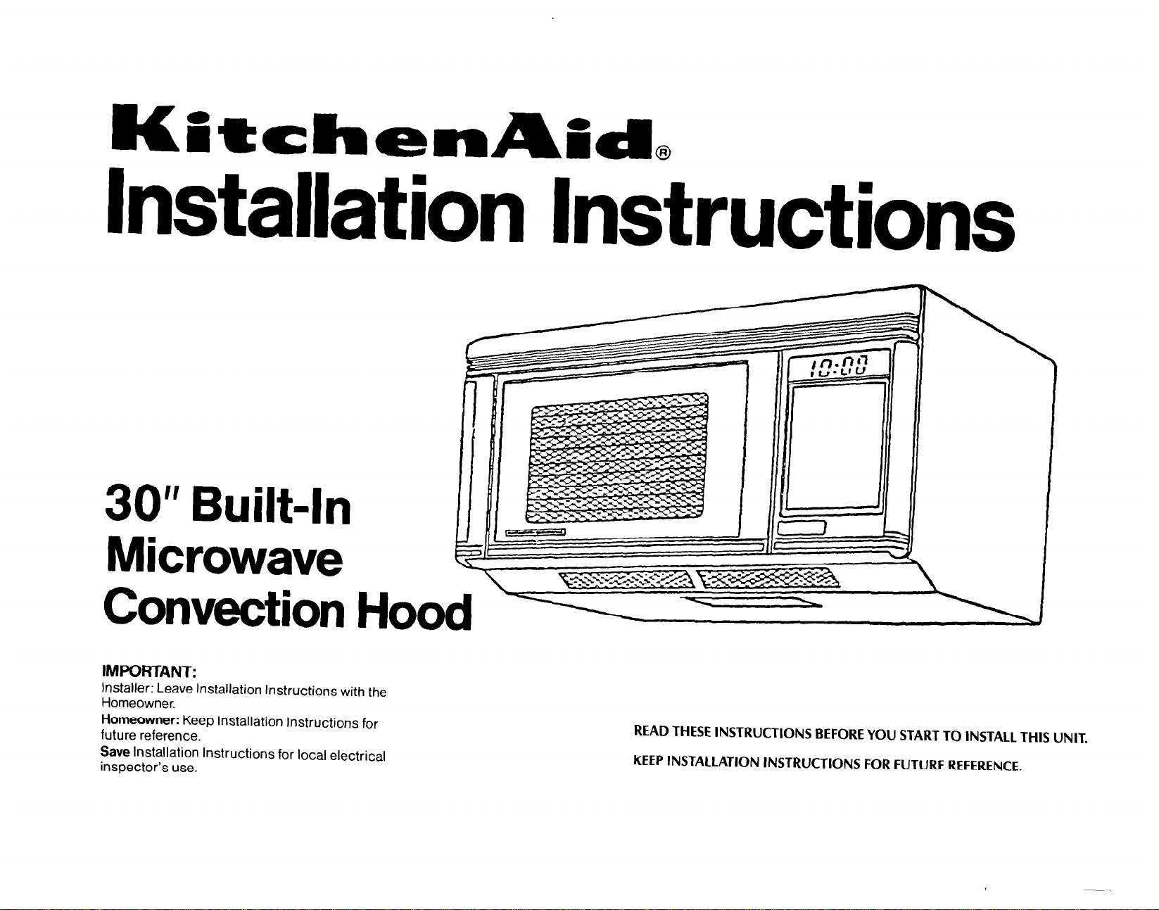
Installation Instructions
30” Built-In
Microwave
Convection Hood L
IMPORTANT:
Installer: Leave Installation Instructions with the
Homeowner.
Homeowner: Keep Installation Instructions for
future reference.
Save Installation Instructions for local electrical
inspector’s use.
READ THESE INSTRUCTIONS BEFORE YOU START TO INSTALL THIS UNIT.
KEEP INSTALLATION INSTRUCTIONS FOR FUTURE REFERENCE.
Page 2
30” BUILT-IN
MICROWAVE /HOOD
CONTENTS:
MODEL
KHMC106W
INSTALLATION INSTRUCTIONS
Introduction
Mounting Space
Wall Construction
Electrical Grounding Instructions.. .........................................
Hood Exhaust Duct..
Tools Recommended for Installation
Installation Hardware
Preparation of Carton
Preparation of Product
Ventilation System
Preparation of Wall and Top Cabinet
Product Installation
Check List for Installation..
Accessories
.......................................................................
..................................................................
...............................................................
...........................................................
......................................
..........................................................
..........................................................
.........................................................
...............................................................
Adapting Hood Fan Unit
Vertical Exhaust, Outside Ventilation..
Horizontal Exhaust, Outside Ventilation
Recirculating, Non-Vented
Mounting Templates
Wall and Top Cabinet
Preparation of Toggle Bolts
..............................................................
Mounting Plates..
Mounting Product
......................................................
.....................................................
............................................
..........................
....................... 7
.........................................
......................................
..................................................
.................................................
........................................
...................................................
.......................................................................
1
1
2
3
4
5
5
6
6
7
7
7
9
10
10
10
.10
11
11
11
.13
.13
Page 3
INTRODUCTION
Proper installation is the installer’s responsibility.
Make sure you have everything necessan/ for correct installation. It is the responsibility of the installer to
comply with the installation clearances specified on the serial/rating plate. The serial/rating plate is located
behind the microwave oven door on the front frame of the microwave oven.
Remove all contents from the upper cabinet.
Important: Observe all governing codes and ordinances.
Check location
microwave oven weight of 150 Ibs., plus the weight of any items placed inside the microwave or the upper
cabinet. The location should be away from strong draft areas, such as windows, doors, and strong heating vents
The microwave oven should be located for convenient use in the kitchen.
Electrical ground
where microwave oven will be installed. The wall must be strong enough to
is required. See Electrical requirements.
Failure to use more than one person during
installation may result in personal injury
A qualified technician should install this microwave oven.
support
the
It is the customer’s responsibility to:
l
contact a qualified electrical installer.
l
assure that electrical installation is adequate
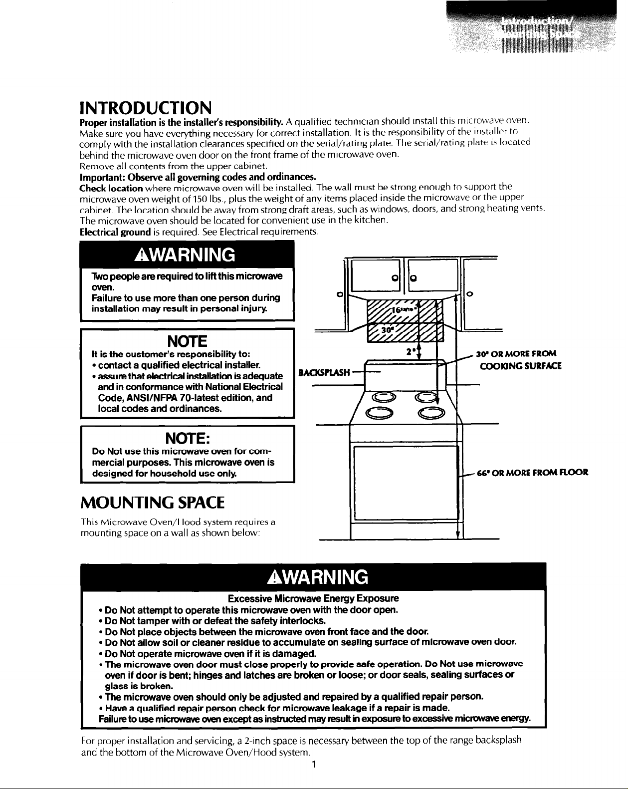
/ 30’
COOKING SURFACE
and in conformance with National Electrical
Code, ANSVNFPA 704atest edition, and
local codes and ordinances.
NOTE:
Do Not use this microwave oven for commercial purposes. This microwave oven is
designed for household use only.
66’ OR MORE FROM FLOOR
r
MOUNTING SPACE
This Microwave Oven/Hood system requires a
mounting space on a wall as shown below:
Excessive Microwave Energy Exposure
l
Do Not attempt to operate this microwave oven with the door open.
l
Do Not tamper with or defeat the safety interlocks.
l
Do Not place objects between the microwave oven front face and the door.
l
Do Not allow soil or cleaner residue to accumulate on sealing surface of microwave oven door.
l
Do Not operate microwave oven if it is damaged.
l
The microwave oven door must close properly to provide safe operation. Do Not use microwave
oven if door is bent; hinges and latches are broken or loose; or door seals, sealing surfaces or
glass is broken.
l
The microwave oven should only be adjusted and repaired by a qualified repair person.
. Have a qualified repair person check for microwave leakage if a repair is made.
Failure to use microwave men except as instructed may result in exposure to excessive microwave energy.
OR
MORE FROM
For proper installation and servicing, a l-inch space is necessary between the top of the range backsplash
and the bottom of the Microwave Oven/Hood system.
1
Page 4
WALL CONSTRUCTION
Personal Injury or Property Damage Hazard
l
This microwave oven must be mounted against and supported by a flat, vertical wall.
l
This microwave oven must be attached with two lag screws to a minimum of one, vertical 2” x 4”
wall stud.
l
Do Not mount microwave oven to an Island or peninsula cabinet.
l
The microwave oven top and rear supporting structures must be capable of supporting 127 Ibs.,
plus the weight of any items placed inside the microwave oven or upper cabinet.
Failure to mount the microwave oven as instructed could result in personal injury and/or property
damage.
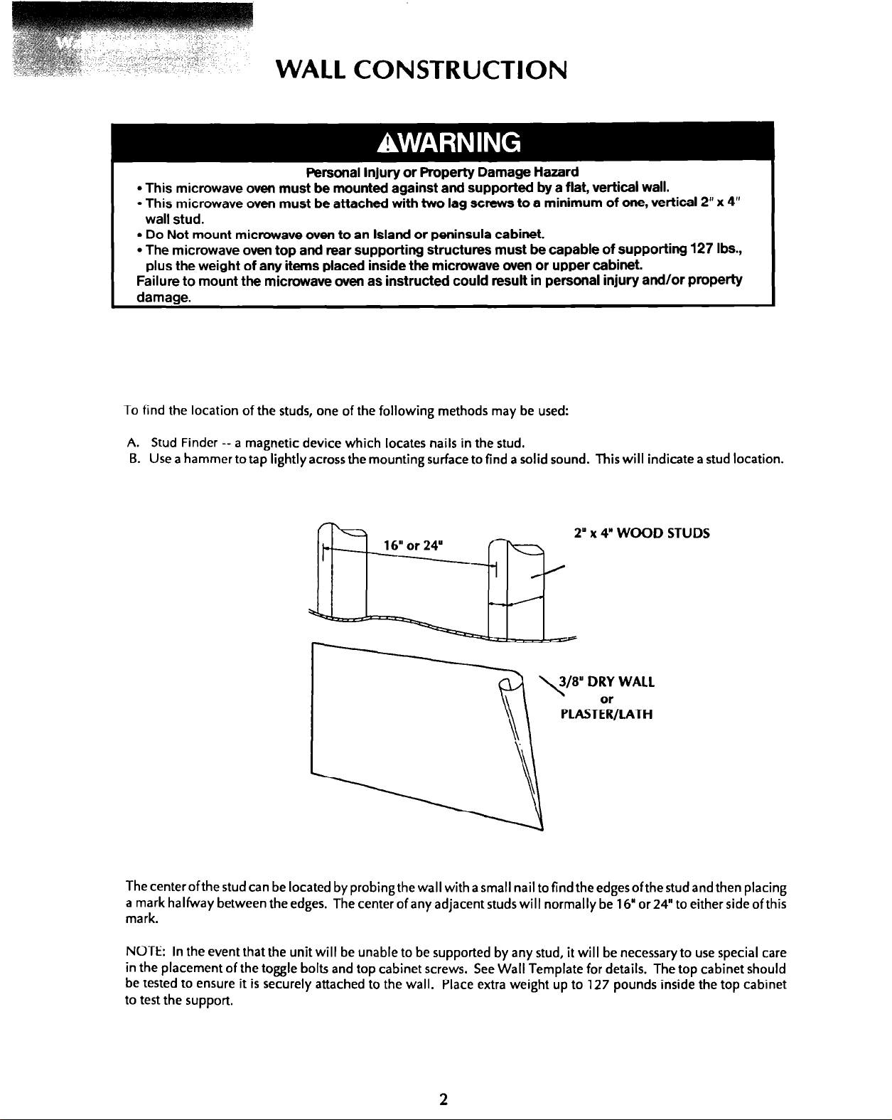
To find the location of the studs, one of the following methods may be used:
A. Stud Finder -- a magnetic device which locates nails in the stud.
B. Use a hammer to tap lightly across the mounting surface to find a solid sound. This will indicate a stud location.
2” x 4”
WOOD STUDS
The centerofthe stud can be located by probing the wall with a small nail to find the edgesofthestud and then placing
a mark halfway between the edges. The center of any adjacent studs will normally be 16” or 24” to either side of this
mark.
NOTE: In the event that the unit will be unable to be supported by any stud, it will be necessary to use special care
in the placement of the toggle bolts and top cabinet screws. See Wall Template for details. The top cabinet should
be tested to ensure it is securely attached to the wall. Place extra weight up to 127 pounds inside the top cabinet
to test the support.
Page 5
ELECTRICAL REQUIREMENTS
Electrical ground is required on this appliance.
E-&~&Hazard
l
Checkwithaqualifiedelectricianifyouareindoubtastowhethertheapplianceisp~perlygrounded.
Improper connection of the equipment-grounding conductor can result in electrical shock.
l
This appliance must be properly grounded.
Failure to do so may result in electrical shock or other personal injury,
l
Do Not use an extension cord with this appliance. Such use may result in a fire, electrical shock
or other personal injury
l
Do Not have a fuse in the neutral or grounding circuit. This could result in electrical shock or other
personal injury
A 12@volt, 60-Hz, AC only, 15- or 20-ampere, fused electrical supply (located in the upper cabinet as close
as possible to the microwave oven) is required. (Timedelay fuse or circuit breaker is recommended.) It
is recommended that a separate circuit serving only this appliance be provided.
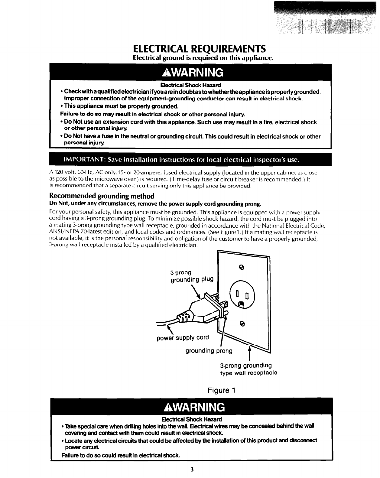
Recommended grounding method
Do Not, under any circumstances, remove the power supply cord grounding prong.
For your personal safety, this appliance must be grounded. This appliance is equipped with a power supply
cord having a 3-prong grounding plug. To minimize possible shock hazard, the cord must be plugged into
a mating 3-prong grounding type wall receptacle, grounded in accordance with the National Electrical Code,
ANSVNFPA 7Watest edition, and local codes and ordinances. (See Figure 1.) If a mating wall receptacle IS
not available, it is the personal responsibility and obligation of the customer to have a properly grounded,
3prong wall receptacle installed by a qualified electrician.
3-prong
grounding Plug
0
powei supply cord
I\
grounding prong
t
3-prong grounding
type wall receptacle
Figure 1
Electrical Shock Hazard
l
Ike special care when drilling holes into the wall. Electrical wires may be concealed behind the wall
covering and contact with them could result in electrical shock
l
Locate any electrical circuits that could be affecW by the installation of this product and disconnect
power circuit
Failure to do so could result in electrical shock
3
Page 6

HOOD EXHAUST DUCT
When the hood is vented to the outside, a HOOD EXHAUST DUCT is required. All ductwork must be metal
(do not use plastic duct). Check that all connections are made securely. Please read the following carefully:
Fire Hazard
Mntirg system must terminate to the outside. Do Not terminate the ductwoh in an attic or other
enclosed space. Do Not use 4” laundrytyp wall caps.
To do any of the above may resutt in a fife.
EXHAUST CONNECTION: The hood exhaust has been designed to connect to a standard 3-l/4” x10”
rectangular duct.
If round duct is required, a rectangular-to-round adaptor must be used. do not use a duct that is
less than
REAR EXHAUST: If a rear or horizontal exhaust is to be used, care should be taken to align the
exhaust with the space between the studs, or wall should be prepared at the time it is constructed by
leaving enough space between wall studs to accommodate exhaust.
MAXIMUM DUCT LENGTH: For satisfactory air movement, the total duct length of 3-1/4”xlO”
rectangular or 6” diameter round duct should not exceed 140 feet.
ELBOWS, ADAPTORS, WALL, ROOF CAPS, etc. present additional resistance to air flow and are equivalent
to a section of straight duct which is longer than their actual physical size. When calculating the total
length, add the equivalent lengths of all transitions and adaptors plus the length of all straight duct sections.
The diagram below shows the approximate feet of equivalent length of some typical ductwork parts. Use
the values in parentheses for calculating air flow resistance equivalent, which should total less than 140 feet.
6”
in diameter.
90°
ELBOW
(r WIDE ELBOW (10 FT.)
(10 FT.1
EXHAUST DUCT
ff2
45’
ELBOW (5 FT.)
90° ELBOW US FT.1
ADAPTOR (5 FT.1
45.
ELBOW (5 FT.)
WALL CAP
WALL AND ROOF CAPS USED MUST HAVE BACK-DRAFT DAMPER.
(40 FT.1
ROOF CAP
4
04 IT.)
Page 7

TOOLS RECOMMENDED FOR INSTALLATION
Phillips Screwdriver
Electric Drill
l/2”, 5/8” and 3/32’ Drill Bits
1 -l/2’ Wood Bit or metal hole cutter (if metal cabinet is used)
Saw to cut exhaust opening (if needed)
Protective drop cloth for product and range. You may use part of the carton for protection.
Knife or single edge razor
Pencil
Measure
Tape
INSTALLATION HARDWARE
The installation hardware (items l- 8) packed with the product should contain the following:
I
1 ITEM NAME
1
2
3
4
5
6
7
8
*There may be leftover screws or toggle bolts depending on installation.
Wood Screw 5 x 30 mm*
Toggle Bolt 3/l 6 inch*
Top Cabinet Screw 5 x 55 mm
Flat Washer 30 mm diameter
Decorative Screw
Power Cord Hanger
Grommet
Exhaust Adaptor Assembly
QUANTITY
6
4
2
2
2
1
1
1
2
0
7
0
0
se with metal cabinets. Surround
e power cord opening. Cut to fit.
8
Page 8

PREPARATION OF
CARTON
Utilization of the canon may make installation easier.
1. Remove product and shipping pads.
Visually check the product after removing from carton.
Remove all packing material from inside the oven cavity.
Check the oven for any damage, such as misaligned door,
damaged gaskets around door or dents inside the oven
cavity or on the door. If there is any damage, please do not
operate the oven until it has been checked by your KitchenAid Dealer and any necessary repairs made.
CHECK THE PRODUCT FOR DAMAGE
PREPARATION OF PRODUCT
1. Rest the product on its side as shown in Figure 1. Use a portion of the carton or some other material
to protect the outercase. Failure to do so could result in damage to the outercase of the unit.
2. pull the two slider levers to release the mounting plate hooks.
back of the product by gently pulling each plate toward you and sliding it to the right. Familiarize
yourself with the operation of the upper hooks and the slider fevers so you will be aware of the proper
procedure for mounting the unit to the wall.
R
emove the mounting plates from the
/
Upper Hooks
\
IQ:
. .
. .
$7
Mounting Plates
I
.
.
.
m
cs=
e
0
irs
Figure 1.
Slider levers
>
Page 9

VENTILATION SYSTEM
THIS MICROWAVE OVEN/HOOD SYSTEM IS DESIGNED FOR ADAPTATION TO THREE TYPES OF HOOD
VENTILATION SYSTEMS:
A. Vertical Exhaust
B. Horizontal Exhaust
C. Recirculating
Select the type required for your installation.
Recirculating (ductless) installation requires
Your Microwave Oven/Hood System is preset for VERTICAL Exhaust; follow the procedure below (A) to attach the
Exhaust Adaptor Assembly if your installation will use a vertical exhaust system. If you will need to use a
HORIZONTAL exhaust system, proceed to step
VERTICAL EXHAUST: Outside Ventilation
A.
The unit is shipped assembled for vertical exhaust. Remove the 2 tapping screws
the Exhaust Adaptor to the fan cover on the top of the outercase cabinet with the 2
shown in
Figure 2.
-- outside ventilation
-- outside ventilation
-- non-vented, ductless
Proceed to
Preparation of Wall and Top Cabinet
CHARCOAL FILTER.
B;
or for a RECIRCULATING system, proceed to page 9 (step C).
from the fan cover. Attach
tapping screws provided as
on page 10.
P
Exhaust Adaptor Assembly - - -
B. HORIZONTAL EXHAUST: Outside Ventilation
Remove and save 3 screws.
1.
Remove fan cover bracket shown in
Fan Cover Bracket - - -
Figure 3.
Figure 2
/
Figure
3
7
Page 10

HORIZONTAL EXHAUST (Continued)
2. Withdraw hood fan unit upward carefully
3. Rotate hood fan unit l/4 turn
as
shown in
(Fig.4).
Figure5
Figure 4
1.
4. Replace hood fan unit into the oven unit.
Be careful not to pinch the lead wire between
the inner bracket and the hood fan unit
Figure 5
(Fig.6).
Figure 6
8
Page 11

HORIZONTAL EXHAUST (Continued)
5.
Replace the fan cover bracket.
Make sure the fan blades are visible through
the rear openings in the cover before proceeding.
.:y 2. --
.; . . . -A.,~*;-,-,
1 ,,
.-.
Attach cover to unit with 3 screws
(Fig. 7).
The hood fan unit is now rotated for horizontal
exhaust operation
See page 11 for exhaust adaptor assembly installation instructions.
C.
RECIRCULATING: Non-Vented, Ductless Operation
1.
Remove and save 3 screws and fan cover bracket as
shown in
2.
Withdraw hood fan unit
3.
Reposition lead wire by carefully pulling the end attache
to the fan unit out of the left side of the holder and re-
positioning it to the right side as shown in Figure 8.
4.
Rotate hood fan unit so exhaust faces toward front of oven.
The fan blades should be visible through the openings
facing toward the front of the oven.
Figure 3,
page 7.
(Figure 4,
page 8)
Figure
Lead Wire Holder
Figure 8
7
5. Replace hood fan unit into unit as shown in
Figure 9
Be careful not to pinch the lead wire between the
inner bracket and the hood fan unit.
6. Replace the fan cover bracket.
If the cover does not fit properly, the hood fan unit
is improperly placed. Check steps 3 and 4 again.
7.
Attach the cover to the oven unit with 3 screws as
shown in
Figure 3,
page 7.
NOTE: 1. The exhaust adaptor assembly is not required for recirculating exhaust.
Figure 9
Page 12

PREPARATION OF WALL AND TOP CABINET
MOUNTING TEMPLATES
THIS PRODUCT CANNOT BE PROPERLY INSTALLED WITHOUT REFERRING TO THE MOUNTING
INSTRUCTIONS FOUND ON BOTH TEMPLATES.
READ AND FOLLOW MOUNTING INFORMATION ON BOTH
WALL AND TOP CABINET
personal Injury or property Dama* Hazard
The mounting area on the top cabinet and wall must be capable of supporting a minimum of127 pounds.
Failure to follow these instructions could result in personal injury and/or property damage.
I
1. If the wall is not flat, use spacers to fill gaps. Mounting plates must be flat for proper installation.
2. Wall space for installation should be the same as the wall template. Make sure the top of the
wall template is at least 66”from the floor and at least 30”from the cooking surface.
For proper rnstallation and servicing, the bottom of the Microwave Oven/Hood system should be
at least 2”above the backsplash of the range.
NOW REFER TO THE WALL AND TOP CABINET TEMPLATES.
PRODUCT INSTALLATION
MOUNTING PLATES
TOP CABINET
AND
WALL
TEMPLATES
I
Electrical Shock Harard
Ike special care when drilling holes into the wall.
EkXt&3lwirtZsnla)/beC%nlX&d
Contact with them could result in electrical shock
Separate toggle bolts from toggle nuts.
Insert one toggle bolt into each of the selected holes in the
mounting plates (these holes correspond to holes in areas
A, B, C
and D ofthe
onto the toggle bolts
do not use a toggle bolt. Use a wood screw. If A, B, C, and
D are not located in studs, follow template instructions for
E and F.
Position the mounting plates with the toggle bolts attached
atthewall locationand inserttoggle nutsand boltsthrough
the holes in the wall with the toggle nuts closed.
Use wood screws to attach mounting plate to studs.
NOTE: Before insertion, be sure you leave a space more
than the thickness of the wall between the mounting plate
and the end of each of the toggle nuts fin the closed
position). If you do not leave enough space, the toggle nut
will not be able to open on the other side of the wall. Also,
once a toggle nut opens, it cannot be withdrawn from the
hole, therefore make sure all toggles are in the correct
position
before
Wall Template)
(Fig, 10).
insertion.
llehindBlewaIcauwing.
and put the toggle nuts
If a hole is located in a stud,
(Fig. 11).
Figure 11
Figure 10
- Wall
4.
Align the mounting plates carefully and hold in position
while tightening toggle bolts. Pull toggle bolt toward you
and turn clockwise to tighten
(Fig. 12).
10
Page 13

If horizontal exhaust is used, attach the exhaust
5.
adaptor assembly to each of the mounting
plates by aligning the holes on the assembly
with the tabs on the plates, holding the assembly in place and bending the tabs to secure
the assembly to the plates (Fig. 13).
Exhaust Adaptor Assembly
Property Damage Hazard
Place a portion of carton or another heavy material over the countertop and range before
installing the microwave oven. Do Not use a plastic cover. Failure to protect cooking surface or
countertop could result in property damage.
zontal exhaust only)
MOUNTING PRODUCT
To attach the Microwave Oven/Hood system to the mounting plates:
Place the product on the top of the protected range cooking surface.
Figure 14
11
Page 14

Thread the oower sunulv cord throueh the hole made at the bottom of the ton cabinet
Personal Injury Hazard
Two people are required to lift this microwave. Failure to use more than one person during installation
may result in oersonal iniurv.
I
Hang the unit on the lower edge of the mounting plates. Rotate the unit upward until it engages the
upper hooks. See
unit is rotated upward. (In the case of a non-recessed bottom in the top cabinet, the hole for the cord
may need to be enlarged.) Remove the carton oortions.
Both upper hooks must be engaged and the unit must be secure before you remove your support.
Failure to do so could result in personal injury or property damage.
I
Raise slider levers at the bottom of the unit up against the unit and insert
each screw with a Phillips head screwdriver. See
Figure 14.
Take care that the power cord is able to clear the edge of the hole as the
Personal Injury Or Property Damage Hazard
decorative
Figure 15.
screws (2). Tighten
I
I
12
I
Decorative Screw
Page 15

8.
Use the two top cabinet mounting screws (C) and flat washers (D), supplied in the installation hardware,
to attach the unit to the top cabinet. See Figurel6. Note: If mounting plates were installed using only
toggle bolts, use the adjusting screws to attach the unit to the top cabinet.
ommet (for metal
Figure1 6
Make a bundle of the power supply cord and attach it to the inside of the cabinet using the cord hanger.
9.
A
short power cord is provided to reduce the risks resulting from contacting the cooking surface or from
becoming tangled.
Electric Shock Hazard
Install power-supply cord bushing around hole drilled in a metal cabinet. Failure to do so could result
in electrical shock.
I
CHECK LIST FOR INSTALLATION
1. Make sure the unit has been installed according to the instructions.
2. Remove all packing material from the oven.
3. Plug in the power cord.
4. Read the Use and Care Guide Manual.
CHECK LIST FOR INSTALLATION
1.
Make sure the unit has been installed according to the instructions.
2.
Remove all packing material from the oven.
3.
Plug in the power cord.
4.
Read the Operation Manual.
5.
Keep these Installation Instructions for the local electrical inspector’s use.
13
Page 16

4 I-?
4S72
PART NO. KHMCIOGW
PRINTED IN U.S.A.
 Loading...