

KITA KP50, KP50P Series, KP50H Series, KP50C Series, KP50V Series Series Manual

PR-0325D 2017/12 Online Version We reserve the right to change the specification without prior notice.
KITA SENSOR TECH. CO., LTD.
www.kita.com.tw
3 MPa 300 kPa
Rated pressure range
Setting pressure range
Withstand pressure
Fluid
Power supply voltage
Current consumption
Temperature characteristic
Port size
Lead wire
Weight
-0.100 ~ 2.00MPa
0.000 ~ 2.00MPa
10.0 ~ -101.3kPa
0.0 ~ -101.3kPa
-101.0 ~ 101.0kPa
-100.0 ~ 100.0kPa
-0.100 ~ 1.000MPa
0.000 ~ 1.000MPa
kPa
kgf/cm
2
bar
psi
inHg
Set pressure
resolution
0.1
MPa
0.001
0.01
0.01
0.1
─
─
─
0.1──
0.001
0.001
0.01
Non-corrosive fluid SUS 316L
Sealed liquid Silicon oil
12 to 24V DC ±10%, Ripple (P-P) 10% or less
±0.3% F.S. ±1 digit
IP65
±3% F.S. of detected pressure (25°C) at temp. Range of 0~50°C
Oil-resistance cable(0.15mm
2
)
A. SPECIFICATIONS
0 ~ 50°C
Approx. 110g (Rear ported) ; Approx. 145g (Bottom ported)
(Positive)
Repeatability (Switch output)
Environment
F1:R1/4", M5 ; F2:NPT1/4", #10-32 UNF ; F3: G1/4"(BSPP), M5
F1C:Rc1/8"
KP50P- -
(High)
KP50H- -
(Vacuum)
KP50V- -
(Compound)
KP50C- -
Output type
Max. load current
Max. supply voltage
Residual voltage
Response time
Output short circuit protection
Yes
≤
40mA (With no load)
1
2
3
4
5
6
7
8
Do not use corrosive fluid SUS316L, please confirm the specification in detailed.
Please use within the rating pressure range. Do not apply pressure beyond recommended maximum withstand pressure,
permanent damage to the pressure sensor may occur.
Do not drop, hit or allow excessive shock. Even if switch body appears undamaged, internal components may be broken and
can cause malfunction.
Turn power off before connecting wiring. Wrong wiring or short circuit will damage and/or cause malfunction.
This product is not explosion-proof rated. Do not use in atmosphere containing flammable or explosive gases.
Wiring for pressure sensor should avoid power source line and high voltage line. If use in the same circuit, noise may cause
malfunction.
The product is complied CE certificate, but no surge absorber. If required, please find other way to solve.
Do not exceed the screw-in torque of 13.6 N.m when installing piping. Exceeding this value may cause malfunction.
2 NPN or 2 PNP open collector
125 mA
≤ 1.5V
30V DC (at NPN output), 24V DC (at PNP output)
Switch
output
LCD display
Switch ON Indicator
Updates time
Indicator accuracy
Enclosure
Operation ambient temp. range
Storage ambient temp. range
Ambient humidity range
Withstand voltage
Insulation resistance
Vibration
Shock
Orange (1 & 2 Indicator) OUT1 OUT2
± 2% F.S. ± 1 digit (ambient temperature: 25 ± 3°C)
About 0.2s
Display
≤
2.5ms (chattering-proof function: 25ms, 100ms, 250ms, 500ms, 1000ms and 1500ms selections)
Voltage
output
Current
output
Voltage
Impedance
Current
Impedance
Linearity ±1% F.S.
4~20mA ( ± 2.5%)
Analog
output
35 ~ 85% RH (No condensation)
-10 ~ 60°C (No condensation or freezing)
250V AC in 1-min (between case and lead wire)
50MΩ (at 500V DC, between case and lead wire)
Total amplitude 1.5mm or 10G,10Hz-55Hz-10Hz scan for 1 minute, two hours each direction of X, Y and Z
100m/s
2
(10G), 3 times each in direction of X, Y and Z
KP50
Series
0.001(~1.999)
0.01(2.00~)
0.01(~19.99)
0.1(20.0~)
0.01(~19.99)
0.1(20.0~)
0.1(~199.9)
1(200~)
For your safety, please read the following before using.
1~5V ( ± 2.5% F.S.)
Max.Load Impedance: 250Ω at power supply of 12V
600Ω at power supply of 24V
Min.Load Impedance: 50Ω
About 1kΩ
3½
digit, 7segment (red/ green)
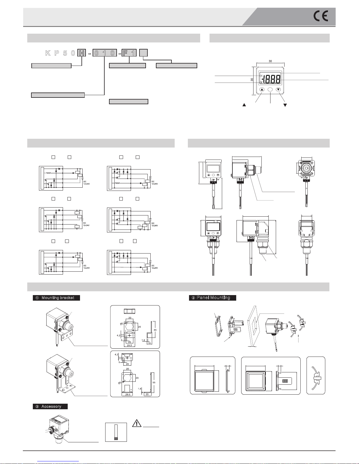
KP50H-010- F1
P:Positive (-0.100 ~ 1.000 MPa)
H:High (-0.100~2.00 MPa)
V:Vacuum (10.0~-101.3 kPa)
C:Compound (-101.0~101.0 kPa)
F1:R1/4", M5
F2:NPT1/4", #10-32UNF
F3:G1/4"(BSPP), M5
F1C:Rc1/8"
(only with rear ported)
010:2 NPN + Analog output (1~5V)
011:2 NPN + Analog output (4~20mA)
02 : 2 NP N + Copy fu nctio n
030:2 PNP + Analog output (1~5V)
031:2 PNP + Analog output (4~20mA)
04 : 2 PN P + Copy fu nctio n
Pressure Range Pressure Port
Blank:Rear ported
L :Bo ttom po rted
Piping Direction
Output Specifications
BT-10:Mounting bracket
BT-11:Mounting bracket
PA-E : Panel adapter
PA-F :Panel adapter + Front protective lid
Optional Parts
Unit:mm
( )Button ( )Button
2 Color Main Display
Setting
Button
Output 1 Indicator
Output 2 Indicator
SET
inHgpsibarkgfkPa
Pressure Unit
Display Section
Front protective lid Panel adapter Panel adapter
39.5
42.5
6.1
40
40
6
35.5
B. ORDERING INFORMATION
D. OUTPUT CIRCUIT WIRING DIAGRAMS
F. OPTIONAL PARTS DIMENSIONS
E. DIMENSIONS
www.kita.com.tw
Display Digital Pressure Sensor
C. PANEL DESCRIPTION
2 NPN +Analog Output (4~ 20m A)
KP50 -011-
RL
RL
RL
Main Circuit
DC(+) (Brown)
DC(-) (Blue)
(Orange)
Analog Output
OUT1(Black)
OUT2(White)
2 NPN+Analog Output (1~5V)
Main Circuit
DC(+) (Brown)
DC(-) (Blue)
(Orange)
Analog Output
OUT1(Black)
OUT2(White)
RL
RL
KP50 -010-
1kΩ
2 PNP+Analog Output (1~5V)
DC(+) (Brown)
DC(-) (Blue)
(Orange)
Analog Output
OUT1 (Black)
OUT2 (White)
KP50 -030-
1kΩ
Main Circuit
RL
RL
2 PNP+Analog Output (4~20mA)
KP50 -031-
RL
RL
RL
Main Circuit
DC(+) (Brown)
DC(-) (Blue)
(Orange)
Analog Output
OUT1(Black)
OUT2(White)
2 NPN +Copy Function
KP50 -02-
RL
RL
Main Circuit
DC(+) (Brown)
DC(-) (Blue)
(Orange)
Copy function
OUT1(Black)
OUT2(White)
2 PNP+Copy Function
KP50 -04-
RL
RL
Main Circuit
DC(+) (Brown)
DC(-) (Blue)
(Orange)
Copy function
OUT1(Black)
OUT2(White)
Unit:mm
1
Mounting bracket
3
Accessory
2
Panel Mounting
Caution:
This device must be
installed to maintain IP 65
(Dust and splash proof)
enclosure rating.
KP50
Series
Hex flat 19
F1L:R1/4",M5
F2L:NPT1/4",#10-32UNF
F3L:G1/4"(BSPP),M5
20
30
41.3
30
30
49.2
64.6
F1:R1/4", M5
F2:NPT1/4", #10-32UNF
F3: G1/4”(BSPP), M5
F1C:Rc1/8"
Hex flat 19
SET
SET
30
41.3
30.2
55.2
2000
20
20
Mounting bracket BT-10
Mounting bracket BT-11
M3*0.5
M3*0.5
BT-10
BT-11
Panel adapter Panel adapter
Front protective lid
36×36 mm
+0.3
-0
t ≤1~5
Dustproof protector
 Loading...