

Kistler-Morse Weigh II User Manual

$15.00 U.S.
Weigh II Installation
and Operation Manual
CAUTION
It is essential that all instructions in
this manual be followed precisely to
ensure proper operation of the
equipment.
97-1120-01
Rev. D
January 2005

NOTICE
The content of this document is the intellectual property of Kistler-Morse. Any reproduction or
translation of this document without the written authorization of a Kistler-Morse corporate officer is
prohibited.
CAUTION
Follow these rules if welding is done on the vessel after installation of Kistler-Morse sensors/
transducers. The electrical current of the welder may pass through the sensor/transducer, causing
damage to it, and possibly to the signal processor. To avoid damage, follow these precautions.
1. Disconnect the sensor/transducer cables from the signal processor.
2. Ground the welder as close to the welding joint as possible.
3. Always ground the welder so that the welding current does not go through the sensor/transducer.
Note
High temperatures can damage sensors/transducers. If you are welding in the vicinity of a
sensor/transducer, monitor the temperature of the metal adjacent to the sensor/transducer. If
it becomes too hot to touch, stop welding immediately, and remove the sensor/transducer
before continuing. Prior to reinstalling the sensor/transducer, verify that no damage has
occurred.

Table of Contents
Table of Contents
Manual Addendum ........................................................................... 1
Chapter 1. Weigh II Introduction ................................................. 1-1
Introduction....................................................................................................................................... 1-1
Modular PCBs ........................................................................................................................... 1-1
Sentry™ .................................................................................................................................... 1-1
Methods of Operation ................................................................................................................ 1-2
Manual Conventions ......................................................................................................................... 1-2
Chapter 2. Hardware Installation................................................ 2-1
General Information .......................................................................................................................... 2-1
Unpacking and Inspection ................................................................................................................ 2-1
Mounting the Weigh II ...................................................................................................................... 2-1
Wiring the Weigh II........................................................................................................................... 2-1
Drilling Holes in Enclosure ........................................................................................................ 2-1
Wiring Power ............................................................................................................................. 2-2
Wiring for Optional PCBs .......................................................................................................... 2-2
Sealing Openings in Enclosure ................................................................................................. 2-2
Power Fuse Information ................................................................................................................... 2-3
Installing PCBs ................................................................................................................................ 2-3
Chapter 3. Menu Tree, Keyboard Functions,
and Quick Start ......................................................................... 3-1
Introduction....................................................................................................................................... 3-1
Menu Tree ........................................................................................................................................ 3-1
Display and Keyboard ...................................................................................................................... 3-4
Auto/Man Key ........................................................................................................................... 3-4
Up Arrow and Down Arrow Keys ................................................................................................ 3-4
Tare/Net/Gross Key ................................................................................................................... 3-5
Menu Key .................................................................................................................................. 3-5
F1, F2, and F3 Keys ................................................................................................................. 3-5
Esc Key..................................................................................................................................... 3-5
(backspace) Key .................................................................................................................... 3-5
Shift Key .................................................................................................................................... 3-6
Enter Key .................................................................................................................................. 3-6
“.” (Period) Key .......................................................................................................................... 3-6
Alphanumeric Keys ................................................................................................................... 3-6
Quick Start ....................................................................................................................................... 3-7
i

Table of Contents
Chapter 4. Display ........................................................................ 4-1
Introduction....................................................................................................................................... 4-1
Avg ................................................................................................................................................... 4-1
Cntby ................................................................................................................................................ 4-2
Units ................................................................................................................................................. 4-3
ID (Identification) .............................................................................................................................. 4-3
Form ................................................................................................................................................. 4-4
ScanT ............................................................................................................................................... 4-5
BarS ................................................................................................................................................. 4-5
Cont .................................................................................................................................................. 4-6
Brite .................................................................................................................................................. 4-6
Time ................................................................................................................................................. 4-7
Zclmp ............................................................................................................................................... 4-7
Hide .................................................................................................................................................. 4-7
Chapter 5. Inputs and Outputs .................................................... 5-1
Introduction....................................................................................................................................... 5-1
SetPt ................................................................................................................................................ 5-1
Descriptions .............................................................................................................................. 5-1
Set ...................................................................................................................................... 5-1
Report ................................................................................................................................. 5-2
Delete.................................................................................................................................. 5-3
Add ..................................................................................................................................... 5-3
Setting Up the Setpoints ........................................................................................................... 5-3
Setpoint Report ......................................................................................................................... 5-4
Iout ................................................................................................................................................... 5-5
Descriptions .............................................................................................................................. 5-5
Set ...................................................................................................................................... 5-5
Mode ................................................................................................................................... 5-6
Rprt ..................................................................................................................................... 5-6
Delete.................................................................................................................................. 5-6
Add ..................................................................................................................................... 5-6
Setting Up the Current Output ................................................................................................... 5-6
Current Output Report ............................................................................................................... 5-8
Serl ................................................................................................................................................... 5-9
HideS ......................................................................................................................................... 5-9
Set ............................................................................................................................................. 5-9
Baud ................................................................................................................................... 5-9
Addr .................................................................................................................................... 5-9
Mode ................................................................................................................................. 5-10
Prnt ................................................................................................................................................ 5-10
Tare .......................................................................................................................................... 5-10
GO1 ......................................................................................................................................... 5-10
GO ALL.................................................................................................................................... 5-10
Timed ....................................................................................................................................... 5-10
Pdly ......................................................................................................................................... 5-10
PLC ................................................................................................................................................ 5-10
ii

Table of Contents
Chapter 6. Calibration .................................................................. 6-1
Introduction....................................................................................................................................... 6-1
Auto .................................................................................................................................................. 6-1
High-Accuracy Calibration ......................................................................................................... 6-2
Calibration by Adding a Known Quantity of Material ................................................................. 6-3
Calibration by Subtracting a Known Quantity of Material.......................................................... 6-5
Refining the Calibration by Setting Zero .................................................................................... 6-6
Displaying the Auto Calibration Parameters.............................................................................. 6-7
Resetting the Auto Calibration Parameters ............................................................................... 6-7
Manual ............................................................................................................................................. 6-8
Displaying the Manual Calibration Parameters ......................................................................... 6-9
Resetting the Manual Calibration Parameters........................................................................... 6-9
Linear ............................................................................................................................................... 6-9
Chapter 7. Service ........................................................................ 7-1
Introduction....................................................................................................................................... 7-1
K-M Service Code...................................................................................................................... 7-1
ADC .................................................................................................................................................. 7-2
Disp ........................................................................................................................................... 7-2
Enab .......................................................................................................................................... 7-2
AdjEx ......................................................................................................................................... 7-3
Res ............................................................................................................................................ 7-3
Gain ........................................................................................................................................... 7-3
Dflt ............................................................................................................................................. 7-3
Filter .......................................................................................................................................... 7-4
Enabe .................................................................................................................................. 7-4
Step..................................................................................................................................... 7-4
Qlfy ..................................................................................................................................... 7-4
DSPfact .............................................................................................................................. 7-5
Trk ............................................................................................................................................. 7-5
Win ..................................................................................................................................... 7-6
Matrl .................................................................................................................................... 7-6
Rate .................................................................................................................................... 7-6
Dflt ....................................................................................................................................... 7-6
DLim ................................................................................................................................... 7-6
Mon ..................................................................................................................................... 7-6
Setpt................................................................................................................................................. 7-6
4/20 .................................................................................................................................................. 7-7
Iadj ............................................................................................................................................. 7-7
Test ............................................................................................................................................ 7-7
Micro ................................................................................................................................................ 7-8
IDrst ........................................................................................................................................... 7-8
KeyT .......................................................................................................................................... 7-8
Prnt ............................................................................................................................................ 7-8
RamT ......................................................................................................................................... 7-8
RsRAM ...................................................................................................................................... 7-9
Access ............................................................................................................................................. 7-9
User ........................................................................................................................................... 7-9
KM ........................................................................................................................................... 7-10
K-M Mfg Code ................................................................................................................... 7-10
iiiii

Table of Contents
Chapter 8. Math Channels........................................................... 8-1
Introduction....................................................................................................................................... 8-1
Math Channel Functions .................................................................................................................. 8-2
Menu Functions ......................................................................................................................... 8-2
Keyboard Functions .................................................................................................................. 8-2
Equation Limitations ........................................................................................................................ 8-2
Enabling a Math Channel ................................................................................................................. 8-3
Setting up a Math Channel .............................................................................................................. 8-4
Error Messages................................................................................................................................ 8-5
Compile Error Codes ................................................................................................................. 8-5
Run Time Error Codes ............................................................................................................... 8-6
Appendix A. Product Specifications ......................................... A-1
Appendix B. Summary of Commands Used When
Vessel Monitoring — Hot Keys ............................................ B-1
Appendix C. Serial Commands.................................................. C-1
Introduction.......................................................................................................................................C-1
Command Table ...............................................................................................................................C-1
Checksum Calculation .....................................................................................................................C-3
Examples .........................................................................................................................................C-4
‘#’ Command — K-M Product Identification Number................................................................. C-4
‘W’ Command — Engineering Units (gross) ............................................................................. C-4
‘B’ Command — Engineering Units (net) .................................................................................. C-4
‘T’ Command — Tare Addressed Vessel ................................................................................... C-4
‘u1’ Command — Request Raw Counts .................................................................................... C-4
Appendix D. Kistler-Morse Service and Warranty ................. D-1
Product Warranty .............................................................................................................................D-1
Service .............................................................................................................................................D-1
Return Material Authorization........................................................................................................... D-2
Address and Telephone Numbers .................................................................................................... D-2
Appendix E. .................................................................................... E-1
Appendix F. Technical Drawings ............................................... F-1
Appendix G. Calculation of
Manual Calibration Parameters ............................................ G-1
Introduction...................................................................................................................................... G-1
Pre-Calibration................................................................................................................................. G-1
Bolt-On Sensors ....................................................................................................................... G-2
Direct Support Sensors ............................................................................................................ G-3
Refining the Calibration ................................................................................................................... G-4
Appendix H. Error Messages ..................................................... H-1
ii
Chapter 1. Weigh II Introduction
Chapter 1. Weigh II Introduction
Modular PCBs
The Weigh II’s modular design provides for
easy system configuration to the specific
needs of your application and allows for
expansion to meet future requirements.
Kistler-Morse’s flexible system allows easy
interconnection to a variety of Programmable
Logic Controllers (PLCs).
The motherboard inside the Weigh II enclosure has three Printed Circuit Board (PCB)
card positions. Optional, modular PCBs plug
onto the motherboard and are accessed
through the front of the enclosure for wiring.
The PCBs available to make up a Weigh II
are:
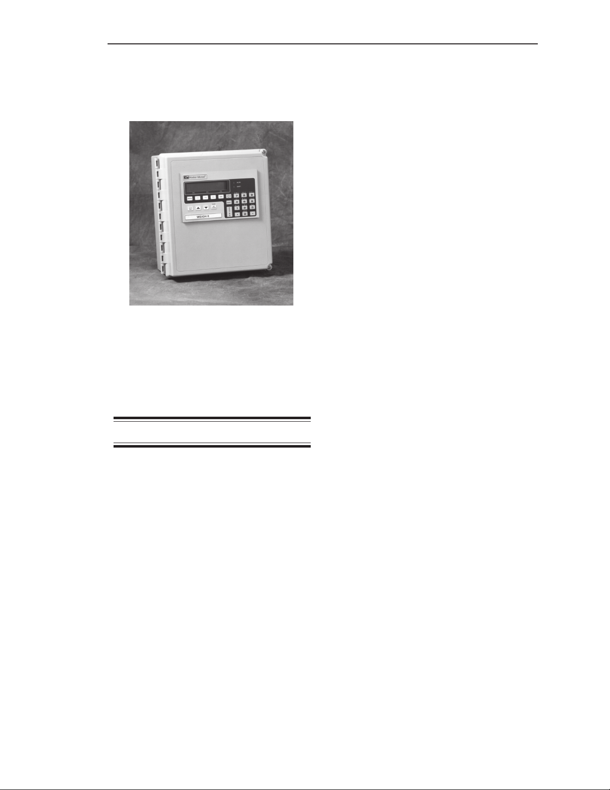
Figure 1-1. The Kistler-Morse Weigh II Strain
Measurement Signal Processor
Introduction
The Weigh II is a multichannel signal processing and display system that will receive
analog inputs and digital serial communications from a master device. The Weigh II can
monitor up to four vessels instrumented with
Kistler-Morse L-Cells, Microcells,
Load Stand II’s, Load Disc II’s, or Load Links,
or with full bridge, foil gage sensors from
other manufacturers. The Weigh II has an
integral, weather-sealed membrane keyboard
and a large LCD display that provide easy
access for programming and viewing parameters and allows the user to input their own
unique vessel identifications. The enclosure is
NEMA-rated, and is wall-mounted. The
Weigh II is available in both AC-powered and
DC-powered versions.
Standard PCBs —
• Display PCB (mounted on inside of
enclosure door)
• Motherboard PCB with an
RS-232/RS-422/RS-485 serial port
(monitors one vessel)
Optional PCBs —
• 4-channel multivessel PCB; monitors up to
four vessels
• 5-channel or 8-channel Setpoint PCB
• 2-channel, 4-channel, or 8-channel Current
Transmitter PCB (for use only with the AC
power version of the Weigh II)
• Combi-Card PCBs for Setpoint and Current
Transmitter functions, in the following
combinations:
2 Setpoints and 1 Current Output
4 Setpoints and 1 Current Output
4 Setpoints and 2 Current Outputs
• Allen-Bradley RIO PCB
• Profibus DP
• Remote Tare PCB (up to 4 channels)
Sentry™
Vibrations in a vessel can cause changes in
a signal processor’s weight display, even
though no material is moved, because the
vibrations affect the vessel’s structural
response. The Weigh II’s unique Sentry™
feature digitally detects, processes, and
filters those vibrations, reducing the fluctuations in weight readings.
1-1

Chapter 1. Weigh II Introduction
Methods of Operation
The Weigh II has two methods of operation:
• Vessel Monitoring — vessel parameters
(weight, level, or some other indication of
vessel contents) are displayed on the LCD.
Vessel monitoring can be set to monitor
and display information on each of the
vessels in the system (Auto Mode)
sequentially or on only one vessel (Manual
Mode). When in the Manual Mode, use of
the keyboard allows the user to manually
scroll to other vessels.
• Menu Operation — system parameters for
display, input/output, calibration,
and troubleshooting can be viewed
and modified.
Note
Throughout this manual, the term
“weight” is used to refer to an indication of the quantity of material in the
vessel. However, the Weigh II can be
set up to display weight, level, volume,
percentage, voltage, or current associated with the material quantity (see
Chapter 4, Display). If you are using
some measure other than weight, all
inputs must be consistent with your
chosen measure.
Manual Conventions
Three kinds of special explanations appear
throughout the manual — WARNING, CAUTION, and Note. The format and significance
of each is defined below:
WARNING
Possible danger to people. Injury
may result if this information is
ignored.
CAUTION
Possible risk to the product. The
Weigh II or other equipment may be
damaged if this information is ignored.
Note
Contains additional information about a
step or feature critical to the installation or operation of the Weigh II.
1-2

Chapter 2. Hardware Installation
Chapter 2. Hardware Installation
Follow this procedure to mount the Weigh II:
General Information
This chapter provides instructions on how to
install and wire the Weigh II.
WARNING
If the Weigh II has been connected
to power, disconnect it before
proceeding. Deactivate power to
the controlled devices to prevent
equipment damage or personal
injury.
1. Hold the Weigh II enclosure against the
wall in the desired location and mark the
positions of the mounting holes. Place the
Weigh II in a safe place.
2. Drill the mounting holes in the wall.
3. Attach the Weigh II to the wall using
hardware that will secure it firmly
in place.
Wiring the Weigh II
Read all instructions before beginning
installation. It is important that all instructions
are followed carefully to ensure that the
equipment is properly mounted and wired.
Unpacking and
Inspection
Carefully remove the components of the
Weigh II from the shipping container and
place them on a flat surface. Visually inspect
for damage that may have occurred during
shipment. If any damage is evident, note it on
the shipping receipt. Report the damage to
the carrier and to Kistler-Morse immediately.
Store the shipping container and packing
material for later use in the event the Weigh II
must be returned to the factory.
Mounting the Weigh II
This section describes how to wire power to
the Weigh II and how to wire the optional
PCBs. Installation and wiring of the KistlerMorse sensors are described in the applicable sensor installation manuals.
Wire routing requirements for the AC and
DC versions of the Weigh II differ, as described below:
• AC Version — Route the AC power cable
and the setpoint cables separate from the
low-level signal cables. Doing
so will avoid electrical interference in
the sensor signals and the communications signals.
• DC Version — Route the DC power cable
separate from any AC power cable and
coaxial cable. Route the setpoint cables
separate from the DC power cable and the
low-level signal cables. Doing so will avoid
electrical interference in the communication signals. Note that you can route the
DC power cable with the low-level signal
cables.
When mounting the Weigh II, be sure there is
enough clearance to open the front door.
Removal and insertion of the modular PCBs
as well as wiring of the sensors and the
PCBs are done through the front of the unit.
The hardware used to mount the Weigh II is
provided by the customer. The Weigh II
enclosure dimensions are shown in
TI-SP.W2-01 in Appendix F, Technical
Drawings. Refer to Appendix A, Product
Specifications, for environmental specifications before mounting the Weigh II.
Drilling Holes in Enclosure
CAUTION
Remove the electronics before drilling
holes in the enclosure. Drill the holes
through the bottom or through the side
of the enclosure. DO NOT drill holes
through the top as this may allow
moisture seepage, which can damage
the electronics.
2-1

Chapter 2. Hardware Installation
The Weigh II enclosure has no openings
through which to route cables or install
conduit. Before you begin wiring, drill entry
holes through the enclosure where it is most
convenient to route your conduit or cables.
Hole location is critical for proper PCB
installation. Check clearances to ensure
fittings and wire routing will not interfere with
the motherboard, option cards, or enclosure
door. Refer to the following drawings in
Appendix F for locations and wiring of the
optional PCBs:
• 4-channel multivessel PCB —
TI-SP.W2-03
• 5-channel or 8-channel Setpoint PCB —
TI-SP.W2.RLY-01
• 2-channel, 4-channel, or 8-channel Current
Transmitter PCB (for use only with the AC
power version of the Weigh II) — TISP.W2.XMIT-01
• Combi-Card PCBs for Setpoint and Current
Transmitter functions —
TI-SP.W2.CMB-01 (AC version) or
TI-SP.W2.CMB-02 (DC version)
• Remote Tare PCB (up to 4 channels) —
TI-SP.W2.RTI-01
• Allen-Bradley RIO PCB — refer to A-B RIO
Manual for Sonologic II and Weigh II
• Profibus DP — refer to Profibus Interface
Manual for Ultra-wave, Sonoglogic II/Weigh
II.
Wiring Power
WARNING
When connecting power to the
Weigh II, adhere to the following:
• Power wiring must comply with
the national wiring requirements
for the country in which the
equipment is installed.
• The ground conductor must be
connected to the Protective Earth
(PE) terminal.
The specifications of the power supply for the
Weigh II are as follows:
AC-Powered Versions
• 100 VAC, or
• 115/230 VAC switch selectable
DC-Powered Version
24 V ± 10% 2A
Refer to the following drawings in Appendix F:
TI-SP.W2-02 for single-point system or
TI-SP.W2-03 for multi-point system. The
wiring procedure for connecting the external
power source to the Weigh II follows:
1. Route the cable from the power source to
TB1 on the motherboard.
2. Connect the Ground lead to the ground
terminal, the Hot lead to the ‘L’ terminal,
and the Neutral lead to the ‘N’ terminal.
Note
The standard lead colors for AC power
in North America are:
• Ground = Green
• Hot = Black
• Neutral = White
3. Restore the power supply.
4. Turn On the On/Off switch (SW1) in the
Weigh II and verify that the LCD activates.
If the LCD does not activate, check that
the wiring is correct and that the power
supply meets specifications.
Wiring for Optional PCBs
Refer to the PCB drawings listed above for
wiring the optional PCBs.
Note
See TI-SP.W2.02 (single-point) or TISP.W2.RTI-01 (multi-point) in Appendix
F, Technical Drawings for wiring details
for the Weigh II’s remote tare function.
To tare the vessel from the remote
station, hold the remote tare push
button for 1 second.
Sealing Openings
in Enclosure
After you have completed installation of the
conduit and cables, seal around the openings
in the Weigh II enclosure to prevent moisture
seepage. Use Sikaflex 1A polyurethane
sealant or RTV 738.
CAUTION
Only use Sikaflex 1A polyurethane
sealant or RTV 738. Other sealants
may contain acetic acid, which is
2-2

Chapter 2. Hardware Installation
harmful to electronics.
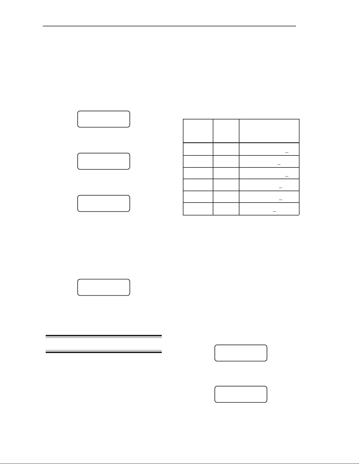
Power Fuse
Information
There are two power fuse locations in the
Weigh II. Refer to Table 2-1 for specification
information on each fuse.
Fuse Part No. Purpose Voltage Current
F1 18-1002-01 AC 250 V 1.0 A
F2 18-1033-13 DC 50 V 1.85 A
Table 2-1. Power Fuse Information
Installing PCBs
The Weigh II arrives from Kistler-Morse with
the specified PCBs installed. However, you
can expand your system by purchasing
optional PCBs and installing them into vacant
positions on the motherboard. There are three
positions on the motherboard of the Weigh II
that accept optional PCBs. Note the following
restrictions on PCB positions in the Weigh II:
• Position 1
4-channel multivessel PCB
• Position 2
5-channel or 8-channel Setpoint PCB
Allen-Bradley RIO PCB
Remote Tare PCB (up to 4-channels)
• Position 3
5-channel or 8-channel Setpoint PCB
Allen-Bradley RIO PCB
Profibus DP
2-channel, 4-channel, or 8-channel
Current Transmitter PCB (for use only
with the AC power version of the
Weigh II)
Combi-Card PCBs
(2 setpoints and 1 current output;
4 setpoints and 1 current output;
or 4 setpoints and 2 current outputs)
• PCB
• Two 4-40 x 1/4 PHS screws to secure the
PCB to the Weigh II motherboard
Refer to the applicable drawing in Appendix F
for PCB slot locations and wiring details and
follow this procedure to install a PCB into the
Weigh II:
1. Disconnect power to the Weigh II.
2. Open the door of the Weigh II.
3. Place the PCB in the designated position
on the motherboard. Be sure the PCB
connector inserts completely into the
motherboard connector.
4. Secure the PCB in place with the two
4-40 x 1/4 PHS screws supplied with
the PCB.
5. Connect the field wiring to the PCB.
6. Restore power to the Weigh II. Close the
door. Installation is complete.
If you add a 4-channel multi-vessel PCB to
the Weigh II, you must use the Enab and Dflt
functions in the ADC Menu of the Service
Menu to bring the new channels on-line. Refer
to Chapter 7, Service, for the use of those
functions.
Note
Before you use the Dflt function to
bring the new channels on-line, write
down all calibration and setup
parameters. The Dflt function will
erase all existing calibration and setup
parameters. Reenter the parameters
after the new channels are on-line.
A new PCB from Kistler-Morse comes with
the following items:
2-3

Chapter 2. Hardware Installation
2-4

Chapter 3. Menu, Tree, Keyboard Functions, and Quick Start
Chapter 3. Menu Tree,
Keyboard Functions,
and Quick Start
Introduction
This chapter describes the Weigh II’s Main
Menu, contains a diagram of the menu tree
structure, and describes all of the keyboard
functions. Additionally, this chapter provides a
list of the steps you need to take to get a
“Quick Start” on using the Weigh II.
Menu Tree
The menu tree of the Weigh II is used to enter
and view settings, set up, calibrate, and
troubleshoot for the system. There are four
submenus listed in the Main Menu:
Chapters 4, 5, 6, and 7 provide detailed
information on the function and use of the
Disp, I/O, Cal, and Service submenus,
respectively.
Note
Some of the submenus are not shown
in the menu tree in Figure 3-1 due to
space constraints. For example, if you
select Disp in Level 1 and ScanT in
Level 2, a menu will come up with
several values to select from for the
ScanT function. For more detail on
submenus, see the appropriate
chapter in this manual.
• Disp — to enter and view display settings
• I/O — to enter and view setpoint param-
eters, current output parameters, serial
port configurations, printer functions, and
PLC interface parameters
• Cal — to calibrate the system
• Service — to troubleshoot the system;
adjust gain, resolution, and excitation; set
up filtering and tracking functions to reduce
the effect of “noise” and drift; reset parameters to default values; calibrate 0/4-20 mA
output; and set up a user access code
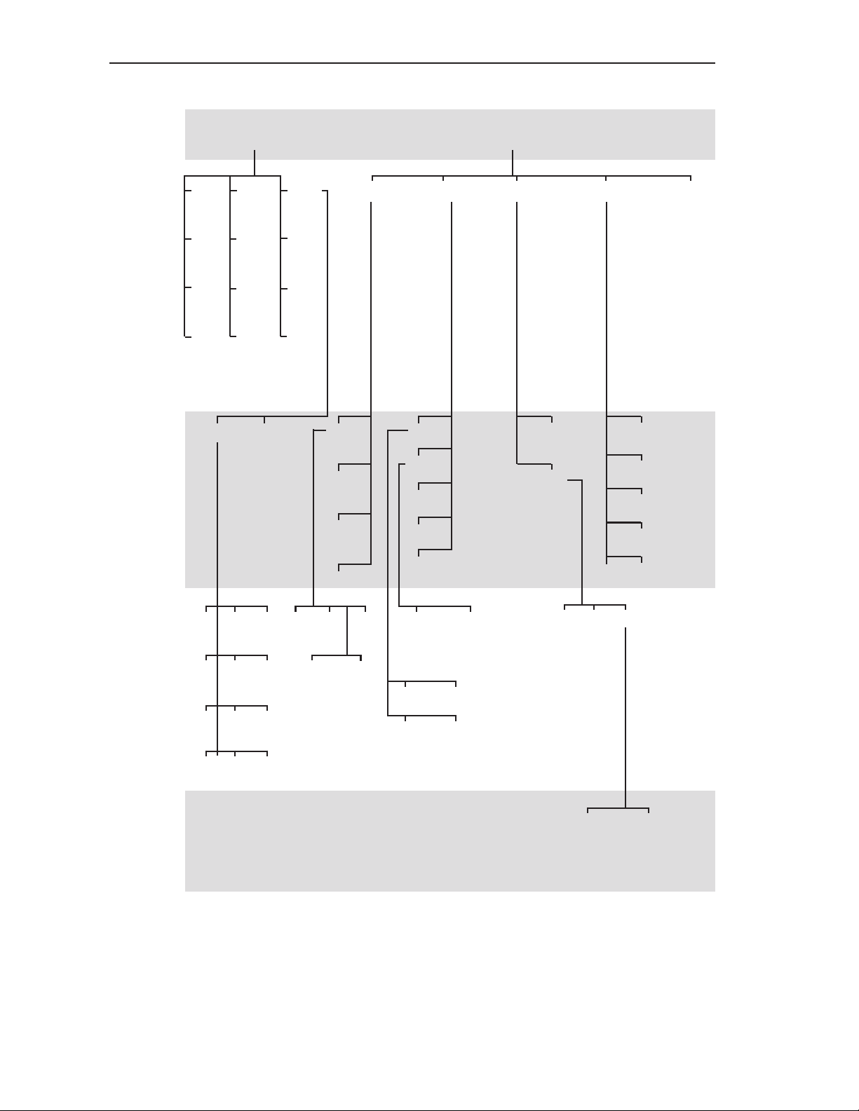
The menu tree in Figure 3-1 shows the Main
Menu in Menu Level 1 and the submenus in
Menu Levels 2 – 5. The menu tree is a quick
reference guide to help you find the functions
you want to perform. For example, if you want
to change setpoint parameters, the menu tree
shows you that setpoints are set up in the
I/O Menu. Level 2 shows the submenus that
are displayed when I/O is selected. Level 3
shows the submenus that are displayed when
a selection is made from Level 2, etc.
3-1
Chapter 3. Menu, Tree, Keyboard Functions, and Quick Start
Menu
Level 1
Menu
Level 2
Menu
Level 3
Disp
(Chapter 4)
Avg
BarS
Time
Common Custom Set
I D
Cntby
Form
Cont
Zclmp
Units
ScanT
Brite
Hide
Report
Delete
I/O
(Chapter 5)
Setpt Iout Serl Prnt PLC*
Set
Mode
Rprt
Delete
HideS
Set
Tare
GO1
GO_ALL
Timed
Menu
Level 4
Menu
Level 5
Add
4-20ma
4/0ma 20ma
Net/Grs
Fsafe
0-20ma
Baud Addr Mode
Printer Slave
lbs
gal
%
V
Kgs
Ltr
ft
mV
tns
Val Dead
Brl
Net/Grs Fsafe
in
mA
Add
Hi/Lo
* Submenus are available for PLC only if your Weigh II includes an
Allen-Bradley RIO PCB, or a Profibus PCB. See A-B RIO Interface
Manual for Ultra-wave, Sonologic II and Weigh II for detailed information or Profibus Interface manual for Ultra-wave/Sonologic II/
Weigh II.
Figure 3-1. Weigh II Menu Tree
PDly
3-2

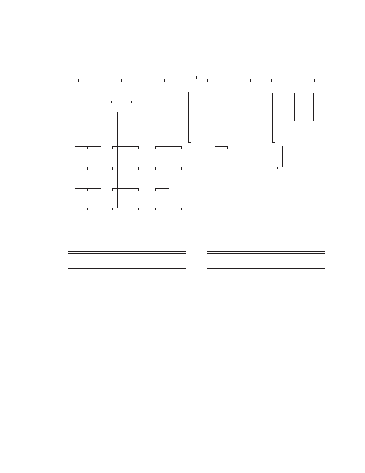
Chapter 3. Menu, Tree, Keyboard Functions, and Quick Start
Cal**
(Chapter 6)
Auto Manual Linear ADC Setpt 4/20 Micro Access
Disp
LoSpan
HiSpan
Zero_Cal
Disply
ScfCnt
ScfWgt
Zero_Cnt
Disply
On
Off
Set
Res
Enab
Gain
Filter
AdjEx
Dflt
Trk
Test
Service
(Chapter 7)
Iadj
Test
IDrst Prnt
KeyT
RamT
RsRAM
User
KM
Reset
Reset
Enabe
Step
Qlfy
DSPfact
Win
Matrl
Rate
Dflt
Dlim
Mon
** If in a Math Channel, the Cal Menu is replaced by the Math Menu.
See Chapter 8, Math Channels, for detailed information.
Figure 3-1. Weigh II Menu Tree (continued)
3-3
Chapter 3. Menu, Tree, Keyboard Functions, and Quick Start
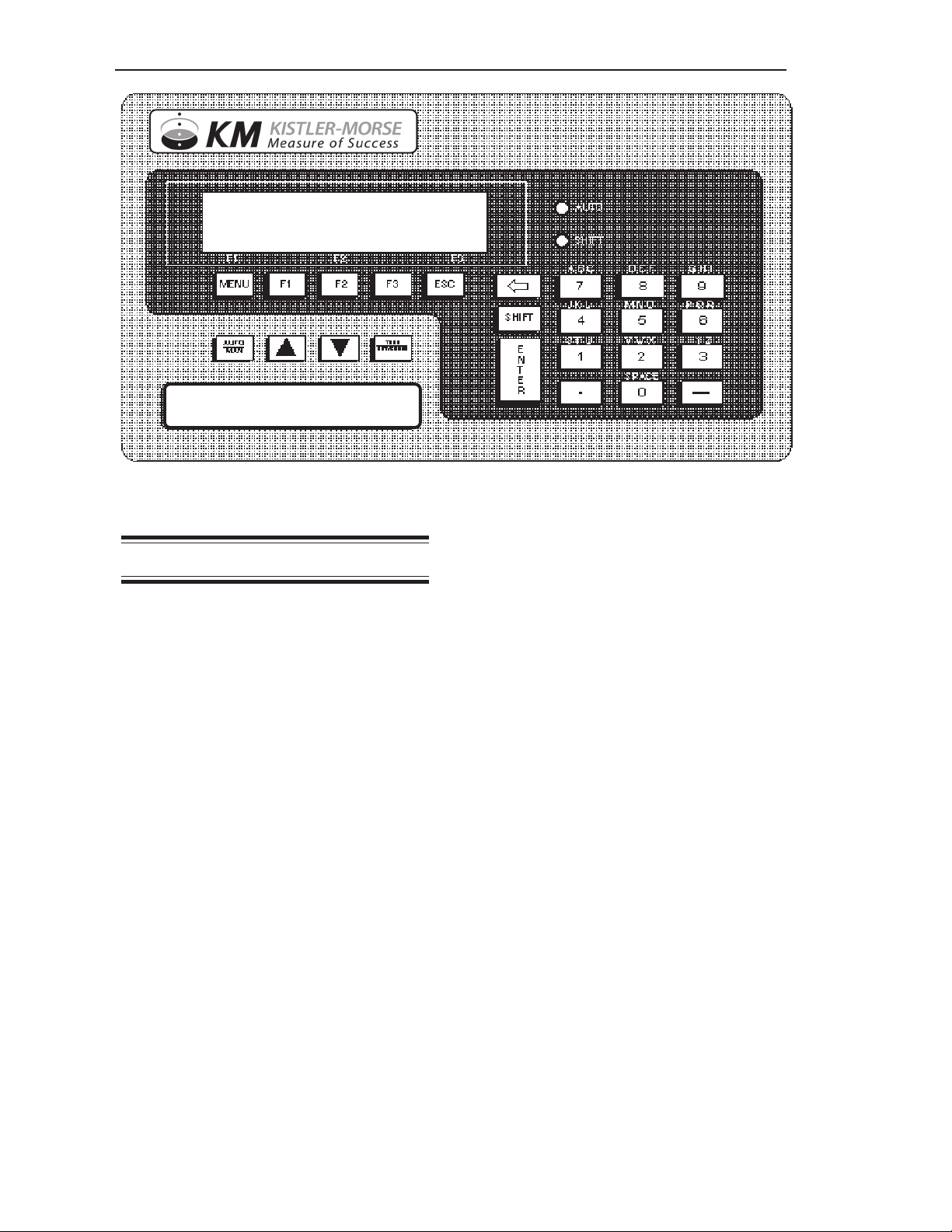
WEIGH II
Figure 3-2. Weigh II Faceplate and Display
Display and Keyboard
The Weigh II (Figure 3-2) has a liquid crystal
display (LCD) panel made up of two
16-character lines, and an integral, weathersealed membrane keyboard. The LCD
displays the vessel ID, material weight
numerically or in a bar graph format, menu
selections, and error messages.
The Weigh II keyboard is used to access the
different menus, scroll through the vessel
monitoring display screens, input setup and
calibration parameters, label the vessel for
easy identification, etc. The function of each
key on the keyboard is described below.
Auto/Man Key
When vessel monitoring, the Weigh II displays the factory-set ID number (or the
customer-defined ID, if input) and material
weight. The Weigh II display can be set up to
scroll automatically through the display
screens for each vessel (Auto Mode) or
remain fixed on a selected vessel (Manual
Mode). The Auto/Man Key toggles between
Auto and Manual Modes:
• When the Weigh II is in the Auto Mode,
the display remains on one vessel for a
preset period of time before scrolling to the
next vessel. The preset display time can
be changed to suit the operator needs,
using the ScanT function (see ScanT in
Chapter 4, Display). The Auto LED to the
right of the LCD is illuminated when the
Weigh II is in the Auto Mode.
• When the Weigh II is in the Manual Mode,
the display remains fixed on a selected
vessel and must be scrolled manually with
the Up Arrow and Down Arrow Keys to
display information on another vessel. The
Auto LED is off when the Weigh II is in the
Manual Mode.
The Auto/Man Key is also used to exit
any function in the menu tree and return
the display to vessel monitoring in the
Manual Mode.
Up Arrow and
Down Arrow Keys
The Up Arrow and Down Arrow Keys are used
to manually scroll the display through the
vessels when the Weigh II is vessel monitoring in the Manual Mode.
These keys are also used to scroll to desired
values when in the menu tree, entering setup
and calibration parameters. For example,
when setting the Lo Span and Hi Span values
in the Auto Cal Menu, the Up Arrow and
Down Arrow Keys can be used to scroll to a
desired value.
3-4

Chapter 3. Menu, Tree, Keyboard Functions, and Quick Start
Tare/Net/Gross Key
The Tare/Net/Gross Key is used when vessel
monitoring in the Manual Mode (Auto LED
off). This key works in conjunction with the
Shift Key:
• When the Shift Key is on (Shift LED
illuminated), the Tare Key is enabled.
Pressing this key ‘tares’ the vessel on the
display, setting the net weight value to
zero. The tare function is useful when you
want to monitor how much material is
added or removed from the vessel from a
given point. To tare the vessel, hold the
Tare Key for 1 second.
• When the Shift Key is off (Shift LED off),
the Net/Gross Key is enabled. Pressing
this key toggles the display between net
weight (weight added or removed from the
vessel since the last time the Tare Key
was enabled) and gross weight (total
weight of material in vessel).
Note
The Weigh II also has a remote tare
function. See TI-SP.W2-02 (singlepoint) or TI-SP.W2.RTI-01 (multi-point)
in Appendix F, Technical Drawings for
wiring details. To tare the vessel from
the remote station, hold the remote
tare push button for 1 second.
Menu Key
Note
The Weigh II must be vessel monitoring in the Manual Mode (Auto LED off)
to access the menus.
Pressing the Menu Key accesses the Main
Menu. If there are multiple pages to a menu,
pressing the Menu Key again scrolls the
display to the next page. For example, the
Main Menu has two pages. The first page
shows:
WII MAIN MENU
Disp I/O Cal
F1 F2 F3
The signifies that there are additional
page(s) to the menu. Pressing the Menu Key
again displays the second page:
WII MAIN MENU
Service
F1 F2 F3
Notice that the second page also has a , to
indicate that there are additional page(s) (in
this case, you have already viewed the other
page). Pressing the Menu Key again returns
the display to the first page.
The Menu Key has the same scrolling
function when a submenu is accessed.
Pressing the Menu Key scrolls through the
different pages of a submenu. Pressing the
Esc Key backs through the submenus one
level at a time and returns to the vessel
monitoring display.
F1, F2, and F3 Keys
The Function Keys — F1, F2, and F3 — are
used to select the items on the menus. The
faceplate has F1, F2, and F3 labeled underneath the LCD. When a menu is displayed,
the menu items are located above these
labels. Pressing the Function Key that
corresponds to the desired menu item
provides access to the menu item.
For example, when the Main Menu is displayed, the selections are:
WII MAIN MENU
Disp I/O Cal
F1 F2 F3
Disp is above the F1 label on the faceplate,
I/O is above the F2 label, and Cal is above
the F3 label. Pressing the F3 Key accesses
the submenus under Cal.
Esc Key
The Esc Key has several functions:
• The Esc Key is used to back through the
submenus one menu level at a time.
Pressing this key while in the Main Menu
returns the display to vessel monitoring in
the Manual Mode.
• The Esc Key also has another function.
The Weigh II arrives from the factory with a
factory-set ID number assigned to each
channel. If you replaced the ID number
with a customer-defined ID while in the
Disp Menu, pressing the Esc Key while
the display is vessel monitoring in the
Manual Mode (Auto LED off) briefly
displays the factory-set ID.
3-5

Chapter 3. Menu, Tree, Keyboard Functions, and Quick Start
Key
“.” (Period) Key
The Key is used to back up the cursor on
the LCD display when using the alphanumeric
keypad.
Shift Key
The Shift LED, located below the Auto LED
on the faceplate, illuminates when the
Shift Key is on. The Shift Key has several
functions:
• The Shift Key is used in conjunction with
the Alphanumeric Keys. When the Shift
Key is on, the keypad types the letters
labeled above the Alphanumeric Key (see
Alphanumeric Keys below for information
on toggling between the letters). When the
Shift Key is off, the keypad types the
number labeled on the key. The Shift Key
is also used in conjunction with other keys
on the panel to provide additional alphanumeric characters.
• The Shift Key is also used in conjunction
with the Tare/Net/Gross Key.
When the Weigh II is vessel monitoring in the
Manual Mode, pressing the “.” Key briefly
displays the current Weigh II software revision
letter and the date of the release.
The “.” Key also functions as a decimal point
when entering numbers in the math channel.
Alphanumeric Keys
The Alphanumeric Keys are used to type in
numbers during setup and calibration.
When the Shift Key is on (Shift LED is
Key Character Character
Shift LED On Shift LED Off
1 S T U 1
2 V W X 2
3 Y Z 3
4 J K L 4
5 M N O 5
Enter Key
The Enter Key has several functions:
• The Enter Key is used to save in memory
any parameter set up in the menus. For
example, if you enter a value in the Cal
Menu, pressing the Enter Key saves it to
memory. The value remains in memory
until a new value is entered.
• When typing in a vessel ID, the Enter Key
advances the cursor one space to the
right.
• When the Weigh II is displaying a numerical value for gross weight in the Manual
Mode, pressing the Enter Key toggles the
display from numerical format to bar graph
format. The display remains in the bar
graph format (even if the
Weigh II is turned off and back on again)
until the Enter Key is pressed to toggle
back to the numerical format.
6 P Q R 6
7 A B C 7
8 D E F 8
9 G H I 9
0 Space 0
. : .
- - -
Menu + * / @ % # & | a b c d e f g h
F1 () {} [] <> i j k l m n o p
F2 ! ^ $ x ‘ , ?; q r s t u v w x
F3
Auto/Man - o º Ö Ü è
Note: Additional characters (parentheses and
symbols) are available using the F1, F2, and F3 Keys,
the Auto/Man Key, the Up and Down Arrow Keys, and
the Tare/Net/Gross Key.
>< º & ! α σ y z , “ ‘ ! : ;
8
Table 3-1. List of Characters Available for
Customer-Defined ID
3-6

Chapter 3. Menu, Tree, Keyboard Functions, and Quick Start
illuminated), the letters above the keys are
accessed for use in inputting a customerdefined ID. Pressing an Alphanumeric Key
repeatedly toggles the display through the
three letters listed above the key. When the
desired letter is displayed, pressing the Enter
Key or a different Alphanumeric Key
advances the cursor one space to the right.
Table 3-1 shows the characters available for a
customer-defined ID.
Quick Start
This section provides a list of the steps you
need to take to get a “Quick Start” on using
the Weigh II.
1. Read the Avg, Cntby, Units, and Form
sections in Chapter 4, Display. Follow the
procedures provided for selecting these
parameters for each vessel.
2. Calibrate the system for each vessel,
using one of the following methods:
• If you can move at least 25% of the
vessel’s maximum live load as part of
the calibration procedure, read the Auto
section in Chapter 6, Calibration.
Follow the procedures provided for
performing the calibration.
• If you cannot move at least 25% of the
vessel’s maximum live load as part of
the calibration procedure, read the
Manual section in Chapter 6, Calibration. Follow the procedures provided for
performing the calibration.
That’s it — you can begin to use your
Weigh II to monitor the contents of your
vessel(s). However, it is recommended that
you read the entire manual for a thorough
understanding of the operation of the Weigh II
and the available options. The manual
explains in detail how to set up setpoints,
current outputs, and serial communications.
3-7

Chapter 3. Menu, Tree, Keyboard Functions, and Quick Start
3-8
Chapter 4. Display
Chapter 4. Display
Disp
Avg Cntby Units ID Form ScanT BarS Cont Brite Time Zclmp Hide
Common Custom
2
1
10
100
1k
20
200
5k
5
50
500
10k
lbs
gal
%
V
Kgs
Ltr
ft
mV
Introduction
1 sec
2 sec
5 sec
tns
XXXXX
Brl
XXX.XX
in
X.XXXX
mA
XXXXX00
XXXX.X
XX.XXX
XXXXX0
Figure 4-1. The Display Menu Tree
Span
Enab
Avg
Set
View
Enab
OffOn
Hi
Lo
NoYe s
On
Off
The Display (Disp) Menu is used to set up
the parameters that govern the display
functions when vessel monitoring. This
chapter covers the functions in the Disp
Menu. Explanations of each of the functions
are provided. Additionally, detailed navigation
procedures through the menu tree are
provided for a few of the functions to help the
user become familiar with the use of the
keyboard functions described in
Chapter 3, Menu Tree, Keyboard Functions,
and Quick Start.
Unless otherwise noted, the display function
for each channel (such as units, ID, etc.) can
be set differently. The descriptions below for
each function note those that are global in
nature and that affect the display for all
channels.
As shown in Figure 4-1, the Disp Menu has
twelve submenus.
This menu is used to set the number of
individual readings (from 1 to 255) the
Weigh II averages for each display reading
while vessel monitoring. The Weigh II calculates a running average. The larger the
number of individual readings in the running
average, the smaller effect a variation in
signal will have on the average. This results in
fewer variations on the display reading and an
easier to read display. Avg affects the value
seen on the display as well as setpoints,
current outputs, and serial outputs. The
default value for Avg is 1.
The number shown upon entry into this menu
is the channel’s current averaging factor. This
number can be modified by using the Up and
Down Arrow Keys or by direct entry with the
Alphanumeric Keys. When the desired
number is shown, pressing the Enter Key
saves the new value.
4-1
Chapter 4. Display
Follow this procedure to modify the averaging
factor.
1. If the Weigh II is in Auto Mode (Auto LED
illuminated), press the Auto/Man Key to
put the system in Manual Mode. The Auto
LED turns off.
2. Use the Up Arrow or Down Arrow Keys to
scroll to the desired channel.
3. Press the Menu Key to display the Main
Menu. The display shows:
WII MAIN MENU
Disp I/O Cal
F1 F2 F3
4. Press the F1 Key to access the Display
Menu. The display shows:
DISPLAY MENU
Avg Cntby Units
F1 F2 F3
5. Press the F1 Key to access the Avg
Menu. The display looks like this:
AVERAGE FACTOR
> X
F1 F2 F3
In place of ‘X’ is the current averaging
factor.
6. Use the keypad or the Up and Down Arrow
Keys to input the value for the averaging
factor. Press the Enter Key to save the
value in memory. The display flashes a
message acknowledging your selection
and returns to:
DISPLAY MENU
Avg Cntby Units
F1 F2 F3
7. Press the Esc Key to scroll up the menu
tree or press the Auto/Man Key to return
the display to vessel monitoring.
Cntby
This menu is used to set up the display to
count by increments of 1, 2, 5, 10, 20, 50,
100, 200, 500, 1000, 5000, or 10000. For
example, a Cntby of 1 would show the
rightmost active digit on the display changing
by increments of 1. A Cntby of 100 would
show the rightmost three active digits on the
display changing by increments of 100 units.
Use Cntby to adjust the display to a resolution consistent with the accuracy of the
system and reduce display flickering.
Example: For a 10,000 lb maximum weight
with a Form of XXXXX, a Cntby of 1 would only
be meaningful if your system accuracy was
+/-.01% of maximum load. A more typical
accuracy would be +/-3%. Since 3% of
10,000 lbs is 300 lbs, a more realistic Cntby
for this system would be 200.
Note that the selection for Form affects how
the Weigh II interprets the Cntby value.
Table 4-1 shows some examples of how
these are related.
Form Cntby Example Value
(incremented digit
underlined)
xxx.xx 1 397.25
xxx.xx 100 397.00
xxxxx 1 39725
xxxxx 100 39700
xxxxxoo 1 3972500
xxxxxoo 100 3970000
Table 4-1. Interaction of Form and Cntby
The default value for Cntby is 1. The current
selection is indicated by an asterisk. The
Cntby function only affects the value seen on
the display. Setpoints, current outputs, and
serial outputs are unaffected by Cntby.
Follow this procedure to modify Cntby.
1. If the Weigh II is in Auto Mode (Auto LED
illuminated), press the Auto/Man Key to
put the system in Manual Mode. The Auto
LED turns off.
2. Use the Up Arrow or Down Arrow Keys to
scroll to the desired channel.
3. Press the Menu Key to display the Main
Menu. The display shows:
WII MAIN MENU
Disp I/O Cal
F1 F2 F3
4. Press the F1 Key to access the Display
Menu. The display shows:
DISPLAY MENU
Avg Cntby Units
F1 F2 F3
4-2

Chapter 4. Display
5. Press the F2 Key to access the Cntby
Menu. The display shows:
CHOOSE COUNTBY
*1 2 5
F1 F2 F3
An asterisk indicates the current
selection.
6. If the displayed menu does not have the
desired countby, press the Menu Key to
display the second page of the menu. The
display shows:
CHOOSE COUNTBY
10 20 50
F1 F2 F3
Continue to press the Menu Key until you
see the desired countby (there are four
pages to the Cntby Menu).
7. Press the F1, F2, or F3 Key to select the
desired countby. The display acknowledges your selection and then returns to:
DISPLAY MENU
Avg Cntby Units
F1 F2 F3
8. Press the Esc Key to scroll up the menu
tree or press the Auto/Man Key to return
the display to vessel monitoring.
Units
This menu allows you to select the unit of
measure for the vessel monitoring display. In
the Common submenu, you can select from
lbs (pounds), Kgs (kilograms), tns (tons), gal
(gallons), Ltr (liters), Brl (barrels), % (percent), ft (feet), in (inches), V (volts), mV
(millivolts), and mA (milliamps). In the
Custom submenu, you can type in a custom
three-character unit of measure. The default
unit is XXX.
Follow this procedure to select a Common
unit of measure.
1. If the Weigh II is in Auto Mode (Auto LED
illuminated), press the Auto/Man Key to
put the system in Manual Mode. The Auto
LED turns off.
2. Use the Up Arrow or Down Arrow Keys to
scroll to the desired channel.
3. Press the Menu Key to display the Main
Menu. The display shows:
WII MAIN MENU
Disp I/O Cal
F1 F2 F3
4. Press the F1 Key to access the Display
Menu. The display shows:
DISPLAY MENU
Avg Cntby Units
F1 F2 F3
5. Press the F3 Key to access the Units
Menu. The display shows:
UNITS OF MEASURE
common custom
F1 F2 F3
6. Press the F1 Key to access the common
Menu. The display shows:
PRE-DEFINED UNIT
lbs Kgs tns
F1 F2 F3
7. If the displayed menu does not have the
desired unit, press the Menu Key to
display the second page of the menu. The
display shows:
PRE-DEFINED UNIT
gal Ltr Brl
F1 F2 F3
Continue to press the Menu Key until you
see the desired unit (there are four pages
to the Common Menu).
8. Press the F1, F2, or F3 Key to select the
desired unit. The display acknowledges
your selection and then returns to:
DISPLAY MENU
Avg Cntby Units
F1 F2 F3
9. Press the Esc Key to scroll up the menu
tree or press the Auto/Man Key to return
the display to vessel monitoring.
ID (Identification)
This menu allows you to type in a
16-character alphanumeric title to identify
each channel on the display in a meaningful
manner. The Weigh II arrives from KistlerMorse with a factory-set ID number assigned
for each channel in the system.
After you have input a customer-defined ID,
you can still view the original factory-set ID
when vessel monitoring in the Manual Mode
by pressing the Esc Key.
Follow this procedure to input a customerdefined ID.
4-3

Chapter 4. Display
1. If the Weigh II is in Auto Mode (Auto LED
illuminated), press the Auto/Man Key to
put the system in Manual Mode. The Auto
LED turns off.
2. Use the Up Arrow or Down Arrow Keys to
scroll to the desired channel.
3. Press the Menu Key to display the Main
Menu. The display shows:
WII MAIN MENU
Disp I/O Cal
F1 F2 F3
4. Press the F1 Key to access the Display
Menu. The display shows:
DISPLAY MENU
Avg Cntby Units
F1 F2 F3
5. Press the Menu Key to display the second
page of the menu. The display shows:
DISPLAY MENU
ID Form ScanT
F1 F2 F3
6. Press the F1 Key to provide a customerdefined ID. The display shows:
EDIT TOP LINE WITH
ALPHA-NUM LABELS
F1 F2 F3
The top line of the display then changes to
the factory-set ID, the Shift LED automatically comes on, and the Weigh II is ready
for you to input the customer-defined ID.
7. Type in the first alphanumeric of the
desired ID. Press the Enter Key or press
the next alphanumeric in the ID (if it is on a
different key than the previous one) to
accept the displayed alphanumeric. The
cursor advances one space to the right.
Notes
1. Type in the first letter of the desired
ID, using an Alphanumeric Key.
Press the Alphanumeric Key
repeatedly to toggle the display
through the three letters listed
above the key until the desired
alphanumeric is displayed.
2. If you want to include a number(s)
in the ID, press the Shift Key; the
Shift LED turns off. Press the
desired Alphanumeric Key.
3. Use the Key to back up the
cursor to correct an entry.
entire customer-defined ID.
9. Press the Esc Key to enter the entire ID in
memory. The display returns to:
DISPLAY MENU
ID Form ScanT
F1 F2 F3
10. Press the Esc Key to scroll up the
menu tree or press the Auto/Man Key to
return the display to vessel monitoring.
Form
This menu allows you to set up the numerical
format by selecting the number of digits to be
displayed to the left and right of the decimal
point while vessel monitoring. Listed below
are the seven different formats available
(x is a place holder):
xxxxx (default) xxxx.x
xxxx.xx xx.xxx
x.xxxx
xxxxxoo xxxxxo
On the display, an asterisk indicates the
format that is currently being used.
Form is used with Cntby and Avg to provide a
stable display for the operator, and to provide
meaningful results consistent with the
system accuracy. For example, you do not
want to have the display showing weights like
1000.01 lbs if the system accuracy is only
+/- 20 lbs.
Follow this procedure to modify Form.
1. If the Weigh II is in Auto Mode (Auto LED
illuminated), press the Auto/Man Key to
put the system in Manual Mode. The Auto
LED turns off.
2. Use the Up Arrow or Down Arrow Keys to
scroll to the desired channel.
3. Press the Menu Key to display the Main
Menu. The display shows:
WII MAIN MENU
Disp I/O Cal
F1 F2 F3
4. Press the F1 Key to access the Display
8. Repeat Step 7 until the display shows the
4-4

Menu. The display shows:
DISPLAY MENU
Avg Cntby Units
F1 F2 F3
5. Press the Menu Key to access the second
page of the Display Menu. The display
shows:
DISPLAY MENU
ID Form ScanT
F1 F2 F3
6. Press the F2 Key to access the Form
Menu. The display shows:
CHOOSE COUNTBY
*1 2 5
F1 F2 F3
An asterisk indicates the current
selection.
7. If the displayed menu does not have the
desired form, press the Menu Key to
display the second page of the menu. The
display shows:
CHOOSE FORMAT
XXXXX* XXXX.X
F1 F2 F3
Continue to press the Menu Key until you
see the desired form (there are four pages
to the Form Menu).
8. Press the F1, F2, or F3 Key to select the
desired form. The display acknowledges
your selection and then returns to:
DISPLAY MENU
ID Form ScanT
F1 F2 F3
9. Press the Esc Key to scroll up the menu
tree or press the Auto/Man Key to return
the display to vessel monitoring.
Chapter 4. Display
BarS
You can choose to view a numerical display
of the weight or a bar graph of a vessel’s
contents while vessel monitoring. The
maximum span for the bar graph and the
selection of the bar graph as the display
option is set with this menu.
The bar graph displays the vessel contents
as a numerical percentage to the left of the
graph, as shown below:
01
50% ! . . . . . . . . . !
The 0% point of the bar graph is always 0.
The 100% point of the bar graph is set by
direct entry using the Alphanumeric Keys or
by scrolling to the desired value with the Up
and Down Arrow Keys. For example, entering
the vessel’s maximum capacity of 5000 lbs
as the BarS value results in a bar graph with
0% corresponding to 0 lbs and 100% corresponding to 5000 lbs. If the gross weight in
the vessel falls outside of the range, the bar
graph display does the following:
• If the gross weight falls below 0 (caused by
inaccuracies in the calibration, vibration,
sensor drift, etc.), the graph remains at
0%, and the numerical percentage remains
at 0%.
• If the gross weight goes above the BarS
value, the graph remains at 100%, and the
numerical percentage reflects the actual
weight. For example, if the BarS value is
5000 lbs and the gross weight is 7500 lbs,
the numerical percentage displayed is
150% while the graph remains at 100%.
ScanT
This menu allows you to choose the amount
of time the Weigh II displays vessel monitoring information before scrolling to the next
channel when in the Auto Mode. Scan time
can be set to 1 second, 2 seconds, or 5
seconds. The default value is 2 seconds. The
current selection is indicated by an asterisk.
The value for ScanT is selected while in the
menu tree for any channel, and applies to all
of the channels in the system.
4-5
The default for the display is bar graph Off
(bar graph not displayed when vessel monitoring). The current selection is indicated by an
asterisk.
If enabled, the bar graph displays for the
vessel while vessel monitoring in both Manual
and Auto modes. While in Manual mode,
pressing the Enter Key toggles the display
between bar graph and numerical display.

Chapter 4. Display
Follow this procedure to set the BarS value
and change the bar graph display option.
1. If the Weigh II is in Auto Mode (Auto LED
illuminated), press the Auto/Man Key to
put the system in Manual Mode. The Auto
LED turns off.
2. Use the Up Arrow or Down Arrow Keys to
scroll to the desired channel.
3. Press the Menu Key to display the Main
Menu. The display shows:
WII MAIN MENU
Disp I/O Cal
F1 F2 F3
4. Press the F1 Key to access the Display
Menu. The display shows:
DISPLAY MENU
Avg Cntby Units
F1 F2 F3
5. Press the Menu Key to display the second
page of the menu. The display shows:
DISPLAY MENU
ID Form ScanT
F1 F2 F3
6. Press the Menu Key to display the third
page of the menu. The display shows:
DISPLAY MENU
BarS Cont Brite
F1 F2 F3
7. Press the F1 Key to access BarS. The
display shows:
BARGRAPH MENU
Span Enab
F1 F2 F3
8. Press the F1 Key to set the Span. The
display looks like this:
The display shows:
BARGRAPH?
On *Off
F1 F2 F3
An asterisk indicates the current
selection.
11. Press the F1 Key to turn the
Bargraph function on; press the F3 Key to
turn the Bargraph function off. This sets
the default display option for the vessel
(the default display option can be overridden while vessel monitoring in Manual
Mode by pressing the Enter Key). The
display flashes a message acknowledging
your selection and returns to:
BARGRAPH MENU
Span Enab
F1 F2 F3
12. Press the Esc Key to scroll up the
menu tree or press the Auto/Man Key to
return the display to vessel monitoring.
Cont
The contrast of the display is adjusted in this
menu. The displayed number ranges from 0
(darkest) to 255 (lightest). The default value is
127. The Up and Down Arrow Keys are used
to make fine adjustments, while the F2 and
F3 Keys are used to make coarse adjustments. The display contrast changes immediately as you make the adjustments. When
the desired results are attained, pressing the
Enter Key saves the new value.
The value for Cont is selected while in the
menu tree for any channel and applies to all
of the channels in the system.
BAR GRAPH SPAN
> X lbs
The unit you set up in the Units Menu
F1 F2 F3
shows in place of lbs.
9. Use the keypad or the Up and Down Arrow
Keys to enter the desired value. Press the
Enter Key to save the value in memory.
The display flashes a message acknowledging your selection and
returns to:
BARGRAPH MENU
Span Enab
F1 F2 F3
10. Press the F3 Key to access Enab.
Brite
The brightness of the display is adjusted in
this menu. This menu is functional only with
the purchase of the Backlight option.
The displayed number ranges from 0 (darkest) to 255 (lightest). The default value is 127.
The Up and Down Arrow Keys are used to
make fine adjustments, while the F2 and F3
Keys are used to make coarse adjustments.
The display brightness changes immediately
as you make the adjustment. When the
desired results are attained, pressing the
4-6

Chapter 4. Display
Enter Key saves the new value.
The value for Brite is selected while in the
menu tree for any channel and applies to all
of the channels in the system.
Time
Time and date are set, displayed, and
enabled in this menu. Accuracy is better than
+/- 1 minute per month, and timekeeping is
maintained for more than 10 years without
power. The date and time are included on
printed output from the Weigh II, so setting
and enabling these functions can help you
maintain good documentation on vessel
contents.
When in the Set Menu, the number/character
displayed directly to the right of the flashing
cursor is modified with the Up and Down
Arrow Keys. Pressing the Enter Key advances the cursor to the next number/
character field. Pressing the Esc Key when
completed setting the time and date enters
the values in memory. Once set, the clock
must be enabled to function. On the display,
an asterisk indicates whether Enab is On or
Off.
Time is set while in the menu tree for any
channel and applies to all of the channels in
the system.
Zclmp
This menu allows the user to set a window
around zero for the gross weight. When the
gross weight value falls within the specified
range (usually indicating a negligible amount
of material in the vessel), the display is forced
to zero.
The user can specify a different range for
gross weight above zero (Hi value) and gross
weight below zero (Lo value). For example, if
the user enters a Lo value of -200 and a Hi
value of 100, all measured gross weights
between -200 and +100 will appear as zero
on the display. If you do not set a non-zero Lo
value, the display may show a small negative
gross weight when the vessel is near empty if
the calibration of the system is not 100
percent accurate. The Zclmp function only
affects the value seen on the display. Set-
4-7
points, current outputs, and serial outputs are
unaffected.
Hi can range from 0 to 255; Lo can range
from 0 to -255. The default values for both are
0. The values can be modified by using the
Up and Down Arrow Keys or by direct entry
with the Alphanumeric Keys. When the
desired number is shown, pressing the Enter
Key saves the new value.
Note that when you input the value for Zclmp,
the display automatically shows any fixed
zeroes or decimal point, consistent with your
selection for Form. Table 4-2 shows some
examples of the maximum value for Zclmp.
Form Maximum Value
for Zclmp
xxx.xx 2.55
xxxxx 255
xxxxxoo 25500
Table 4-2. Interaction of Form and Zclmp
Hide
This menu allows you to ‘hide’ a channel(s)
from the scanning sequence on the display.
The Weigh II continues to monitor the
channel(s) that is hidden, but does not
display it. This function is useful if you are not
using all of the available channels to monitor
vessels, want to observe specific channels
without taking the other channels in the
system off-line, or want to hide math
channel(s) that contain intermediate results.
The default for Hide is Off (i.e., the channel is
not hidden).
Follow this procedure to hide channels.
1. If the Weigh II is in Auto Mode (Auto LED
illuminated), press the Auto/Man Key to
put the system in Manual Mode. The Auto
LED turns off.
2. Use the Up Arrow or Down Arrow Keys to
scroll to the desired channel.
3. Press the Menu Key to display the Main
Menu. The display shows:
WII MAIN MENU
Disp I/O Cal
F1 F2 F3

Chapter 4. Display
4. Press the F1 Key to access the Display
Menu. The display shows:
DISPLAY MENU
Avg Cntby Units
F1 F2 F3
5. Press the Menu Key three times to
access the fourth page of the Display
Menu. The display shows:
DISPLAY MENU
Time Zclmp Hide
F1 F2 F3
6. Press the F3 Key to access the Hide
Menu. The display shows:
HIDE VESSEL
On *Off
F1 F2 F3
An asterisk indicates the current
selection.
7. Press the F1 Key to hide the channel. The
display acknowledges your selection and
then returns to:
DISPLAY MENU
Time Zclmp Hide
F1 F2 F3
Note
The Weigh II will not hide any channel
until you enable the Hide function,
described below in Step 8.
8. Press the Esc Key two times or press the
Auto/Man Key to return to vessel monitoring. While in vessel monitoring in the
Manual Mode, press the Shift Key (Shift
LED illuminated) and then press the ‘9’
Key to enable the Hide function. The
display acknowledges that Hide is enabled. All channels that have On selected
in the Hide menu will not display until you
disable the Hide function (see Step 9
below).
9. To display the hidden channels again,
while vessel monitoring in Manual Mode
press the Shift Key (Shift LED illuminated)
and then press the ‘9’ Key. The display
acknowledges that Hide is disabled, and
the display will now show all channels
again.
4-8
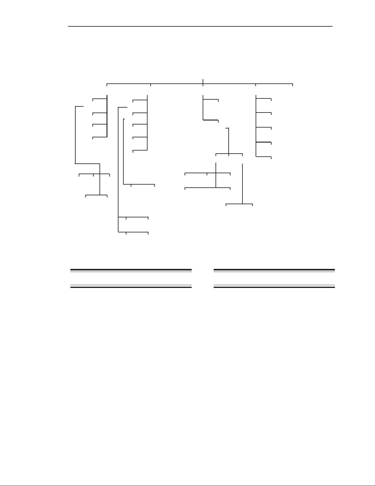
Chapter 5. Inputs and Outputs
Chapter 5. Inputs and Outputs
I/O
Setpt Iout Serl Prnt PLC
Set
Report
Delete
Add
Val
Dead
Net/Grs Fsafe
Hi/Lo
Set
Mode
Rprt
Delete
Add
4-20ma
4/0ma 20ma
Net/Grs
Introduction
HideS
Set
Addr
Baud
1200 2400 4800
0-20ma
Fsafe
9600 19200
Printer Slave
Figure 5-1. The Input/Output Menu Tree
SetPt
Mode
Tare
GO1
GO_ALL
Timed
PDly
The I/O Menu is used to enter parameters for
setpoints, current output (4-20 mA, 0-20 mA),
serial port configuration, printer functions, and
PLC interface. This chapter covers the
functions in the I/O Menu. Explanations of
each of the functions are provided. Additionally, detailed navigation procedures through
the menu tree are provided for the setpoint
and current output functions.
As shown in Figure 5-1, the I/O Menu has five
submenus:
1. Setpt — used to set up setpoints to
activate or deactivate a relay
2. Iout — used to set up current outputs
3. Serl — used to set up serial communications settings for use with a PLC,
printer, etc.
4. Prnt — used to direct output to a printer
5. PLC — used to set up communications
with a PLC
5-1
The setpoint value is the weight measurement
in a vessel where you wish a device (for
example, a pump) to activate or deactivate.
The setpoint setup functions for each vessel
are accessed in this menu. They include
adding and deleting setpoints and selecting
activation levels, high or low activation,
deadband values, fail-safe parameters, and
net or gross weight.
The Descriptions section defines each of the
parameters. The Setting Up the Setpoint and
Setpoint Report sections provide the detailed
procedures for using the Weigh II.
Descriptions
Set
This menu is used to select the setpoint to
be set up for the displayed vessel. Depending
on the options you selected for your Weigh II,
up to eight setpoints can be assigned per

Chapter 5. Inputs and Outputs
vessel or math channel. These are labeled
SP1 for setpoint 1 through SP8 for setpoint 8.
Note
Depending on the options you
selected, up to a total of 16 setpoints
can be assigned in the Weigh II, with a
maximum of 8 setpoints for one vessel
or math channel.
Once you have selected a setpoint to set up,
the activation value (Val), the point where the
setpoint relay changes state, can be entered.
This value is entered directly with the Alphanumeric Keys or scrolled to with the Up and
Down Arrow Keys. The “-” Key is used to
toggle between the positive and negative
value of the number entered. Setpoint relays
can be configured to change state either
above (Hi) or below (Lo) the setpoint value.
The deadband (Dead) value determines the
point at which a setpoint relay returns to its
normal on/off state after the relay has been
activated. The deadband value equals the
amount of material that will be added or
removed from the vessel before the setpoint
relay is deactivated. Kistler-Morse recommends the use of a non-zero deadband to
prevent relays from oscillating. The value is
entered directly or scrolled to with the arrow
keys. The default value is 10. Pressing the
Enter Key saves the new value.
The setpoint relays can be set to activate
from the net weight or the gross weight
(Net/Grs) of the material in the vessel.
Activating based on the gross weight is the
default mode of the Weigh II.
Example: See Figure 5-2. A vessel with a
9,300 lb capacity has setpoint 1 (SP1) set at
9,000 lbs gross weight. The Hi/Lo function is
set to Hi and the deadband (Dead) is set at
1,000 lbs. When the contents exceed 9,000
lbs, the setpoint energizes, activating a pump
to remove material from the vessel. The pump
continues to operate until the setpoint deenergizes at a material weight of 8,000 lbs
(9,000 lbs minus the 1,000 lb deadband).
This vessel also has a setpoint 2 (SP2) set at
2,000 lbs gross weight. The Hi/Lo function is
set to Lo and the deadband (Dead) is set at
500 lbs. When the contents falls below 2,000
lbs, the setpoint energizes, activating a pump
to fill the vessel. The pump continues to
operate until the setpoint de-energizes at a
material weight of 2,500 lbs (2,000 lbs plus
the 500 lb deadband).
Hi
SP1=9,000
Deadband = 1,000
8,000
2,500
Deadband = 500
Lo
SP2=2,000
Figure 5-2. Setpoint Example
If the Weigh II detects a problem, one of three
fail-safe (Fsafe) conditions can be applied to
a setpoint:
1. On
2. Off — default
3. NC (no change)
The On setting energizes the setpoint in a
fail-safe condition. The Off setting deenergizes the setpoint in a fail-safe condition.
The NC setting means no change is made to
the setpoint condition in a fail-safe condition
(i.e., whatever was energized before the
problem was detected will continue to be
energized). A fail-safe condition remains in
effect until the problem has been corrected.
The following are examples of conditions of
fail-safe conditions:
• ADC (analog-to-digital converter)
overrange/underrange condition
• Engineering units overrange
Report
When this menu is accessed, the display
shows all setpoints assigned to the current
vessel. A typical display looks like this:
SP2 Output Chan
Slot 02 Chan# 03
F1 F2 F3
• SP2 is the setpoint label
• Slot 02 is the slot number of the setpoint
PCB
• Chan# 03 is the relay channel of the
setpoint on the setpoint PCB
Pressing any key other than the Esc Key or
Auto/Man Key cycles through the reports for
all other assigned setpoints for this vessel.
5-2
 Loading...