

Kistler-Morse Microcell Installation Manual

Microcell™
Installation Manual
CAUTION
It is essential that all instructions in this
manual be followed precisely to ensure
proper operation of the equipment.
97-1012-02
Revision G
March 2010

NOTICE
The content of this document is the intellectual property of Kistler-Morse® Corporation. Any
reproduction or translation of this document without the written authorization of a Kistler-Morse
corporate ofcer is prohibited.
®
CAUTION
Follow these rules if welding is done on the vessel after installation of the Microcell™ system. The
electrical current of the welder may pass through the Microcell™, causing damage to the sensor and
possibly to the signal processor. To avoid damage, follow these precautions:
1. Disconnect the Microcell™ cables from the signal processor.
2. Ground the welder as close to the welding joint as possible. The welding ground must be between
the Microcell™ and the weld joint to prevent the welding current from going through the Microcell™
to earth ground.

TABLE OF CONTENTS
CHAPTER 1. INTRODUCTION ................................................................................................................ 1
Equipment Description ......................................................................................................................... 1
Applications .......................................................................................................................................... 1
Manual Conventions ............................................................................................................................. 1
CHAPTER 2. PRE-CHECK PROCEDURES ............................................................................................ 2
Introduction ................................................................................................................................................ 2
Application Verication ............................................................................................................................... 2
Order Verication ........................................................................................................................................ 2
Microcell™ Order ................................................................................................................................. 2
Microcell™ Installation Equipment ....................................................................................................... 3
Junction Box and Field Wiring Equipment ........................................................................................... 3
Checking Equipment .................................................................................................................................. 3
Visual Check ......................................................................................................................................... 3
Functional Check .................................................................................................................................. 3
Testing with Kistler-Morse® Test Meter ........................................................................................... 3
Testing with Digital Multimeter (DMM) ............................................................................................. 4
CHAPTER 3. MICROCELL™ INSTALLATION ON VERTICAL COLUMN LEGS .................................... 5
Introduction ................................................................................................................................................ 5
Mounting Locations .................................................................................................................................... 5
Microcell™ Sets ................................................................................................................................... 5
Best Performance ........................................................................................................................... 5
Standard Performance ................................................................................................................... 5
Horizontal Distribution of Microcell™ Sets ........................................................................................... 6
Vertical Location of Microcell™ Sets .................................................................................................... 6
Column Legs without X-Braces ...................................................................................................... 6
Column Legs with X-Braces ........................................................................................................... 6
Installing Microcell™ Sets .......................................................................................................................... 8
Surface Preparation .............................................................................................................................. 8
Drill and Tap .......................................................................................................................................... 8
Mounting the Microcell™ Sets ............................................................................................................. 9
Mounting Junction Box ............................................................................................................................ 10
Mounting Location ............................................................................................................................. 10
Junction Box Installation .................................................................................................................... 11
Wiring Microcells™ to Junction Box ........................................................................................................ 11
Wiring Junction Boxes Together and to Signal Processor ....................................................................... 13
Installing Insulation for Outdoor Vessels (Optional) .................................................................................. 15
Insulation Order and Installation Equipment ...................................................................................... 15
Installing Brace Wrap ......................................................................................................................... 15
CHAPTER 4. MICROCELL™ INSTALLATION ON HORIZONTAL BEAMS .......................................... 17
Introduction .............................................................................................................................................. 17
Mounting Locations .................................................................................................................................. 17
Microcell™ Sets ................................................................................................................................. 17
Distribution of Microcell™ Sets .......................................................................................................... 17
Installing Microcell™ Sets ........................................................................................................................ 20
Surface Preparation ............................................................................................................................ 20
Drill and Tap ........................................................................................................................................ 20
Mounting Microcell™ Sets ................................................................................................................. 21

TABLE OF CONTENTS
Mounting Junction Box ............................................................................................................................ 22
Mounting Location.............................................................................................................................. 22
Junction Box Installation .................................................................................................................... 22
Wiring Microcell™ Sets to Junction Box .................................................................................................. 23
Wiring Junction Boxes Together and to Signal Processor ....................................................................... 24
CHAPTER 5. SYSTEM CALIBRATION .................................................................................................. 27
Introduction .............................................................................................................................................. 27
Live Load Calibration ............................................................................................................................... 27
Adding a Known Quantity of Material ................................................................................................. 27
Removing a Known Quantity of Material ............................................................................................ 28
Manual Calibration ................................................................................................................................... 28
CHAPTER 6. TROUBLESHOOTING ...................................................................................................... 29
Problem 1. Small Amplitude Changes or Erratic Fluctuations in Display Readings ............................... 29
Problem 2. Repeatable Drift Over a 24-hour Period ............................................................................... 30
Problem 3. Sudden Change in Weight Reading or System Requires Frequent Recalibration ................ 31
APPENDIX A. MICROCELL™ SPECIFICATIONS ................................................................................. 32
APPENDIX B. GLOSSARY ..................................................................................................................... 34
APPENDIX C. ALTERNATE METHOD FOR CHECKING OUTPUT ...................................................... 35
APPENDIX D. SPARE PARTS RECOMMENDATIONS ......................................................................... 36
APPENDIX E. TECHNICAL DRAWINGS ............................................................................................... 37
CHAPTER 1. INTRODUCTION
APPLICATIONS
The 3” Microcell™ can be installed on carbon
steel, stainless steel, or aluminum vessel supports.
The 2” Microcell™ can be installed on carbon steel
vessel supports only. Refer to Appendix A
(Microcell™ Specications) for stress limits on
each type of Microcell™.
Microcell™ sets can be installed on leg-supported
and beam-supported vessels. Refer Chapter 3
for installation details on installing Microcell™ on
vertical column legs. Refer to Chaper 4 for
installation details on installing Microcell™ on
horizontal beams.
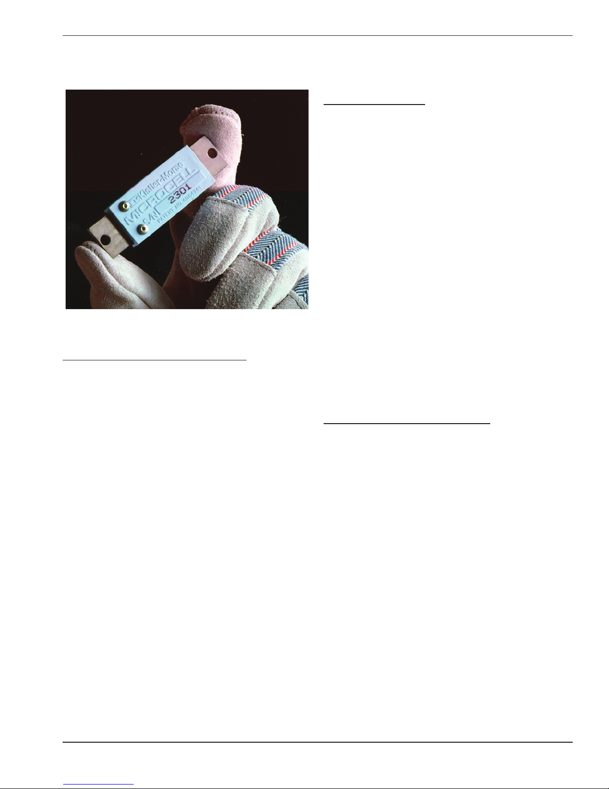
Figure 1-1. The Kistler-Morse® Microcell™.
EQUIPMENT DESCRIPTION
The Microcell™ (Figure 1-1) is a highly sensitive
bolt-on strain gage sensor used to determine the
weight of material contained in storage vessels.
Microcell™ sets bolt onto a vessel’s metal support
structure. As weight is added to or removed from
the vessel, the vessel support structure
experiences strain changes proportional to the
weight changes. The Microcell™ detects the
strain changes and produces a voltage output
proportional to those changes, thus indicating the
change in weight. Kistler-Morse® signal
processors convert the Microcell™ voltage outputs
to weight or level. Refer to Appendix A for
specications.
The Microcell™ is easy to install. It mounts to the
surface of the structural support and never comes
in contact with the vessel contents. Used in many
different industries, it can weigh any type of
material stored in a vessel with metal support
members. The Microcell™ is rugged, can operate
in industrial environments, and requires no periodic
maintenance. It is immune to electrical noise due
to its high-level output voltage.
Contact Kistler-Morse® for information on
non-standard applications.
Be sure to read the entire installation procedure
pertaining to your application before beginning
installation.
MANUAL CONVENTIONS
Three kinds of special explanations appear
throughout the manual. The format and
signicance of each is dened below:
WARNING
Possible danger to people. Injury may result
if this information is ignored.
CAUTION
Possible risk to the product. The Microcell™
or other equipment may be damaged if this
information is ignored.
Note
Contains additional information about a step or
feature critical to the installation or operation of
the Microcell™.
1

CHAPTER 2. PRE-CHECK PROCEDURES
INTRODUCTION
This chapter describes the pre-check procedures
for Microcell™ sets. Verifying the application and
checking the Microcell™ sets before installation
will ensure installation of properly working
equipment that will provide accurate monitoring
of vessel contents.
APPLICATION VERIFICATION
Prior to ordering Microcell™ sets, be sure to have
read the Microcell™ Selection Guide
(Kistler-Morse® #97-5023) and completed the
appropriate Application Data Form (Kistler-Morse®
#97-5025 for Microcells™ on vertical column legs
or Kistler-Morse® #97-5024 for Microcells™ on
horizontal beams). A copy of the completed form
was returned with both the order acknowledgment
and equipment shipment. If you cannot locate the
form, contact Kistler-Morse® to get another copy
before proceeding. Review the information on the
form now to verify the application details.
Note
If the calculated stress on the Application Data
Form is outside the following ranges, this is a
special application:
3” Microcell™: 2,500 psi - 7,500 psi
(1.8kg/mm2 - 5.3kg/mm2)
2” Microcell™: 3,750 psi - 11,250 psi
(2.6kg/mm2 - 7.9kg/mm2)
ORDER VERIFICATION
Prior to beginning installation, verify the order is
complete and assemble additional equipment
needed for the installation.
MICROCELL™ ORDER
The following are included with the order
(quantities dependent on application):
STANDARD
Microcell™ set, each complete with:
Sensor
Environmental Cover
#8-32 socket head cap screws (2)
#8 hardened at washers (2)
JB1 or JB2 Junction Boxes, each complete with:
Terminal board
Watertight ttings (4)
Watertight plugs (for any cable openings that
will not be used)
Installation Kit, each complete with:
Microcell™ drill template with #8-32 socket
head cap screw
#29 drill bit
#8-32, 2-ute, spiral-point tap
Sikaex 1A polyurethane sealant or Dow
Corning RTV 738 or RTV 739 and Material
Safety Data Sheet (MSDS)
Rust-inhibiting silicone grease
OPTIONAL
Insulation and insulation hardware (if best
performance is required for an outdoor
installation on column legs)
Contact Kistler-Morse® before proceeding further
with a special application.
If any items are missing from the order, contact
Kistler-Morse® before proceeding. Substituting
parts without Kistler-Morse® approval may cause
system problems and will void the warranty.
Note
A signal processor and its manual are required
to calibrate the system. If using an existing
signal processor, this will not be included in
the order.
2

MICROCELL™ INSTALLATION EQUIPMENT
Tape measure
Marking pen
Kistler-Morse® Test Meter
Kistler-Morse® Microcell™ Sensor Drill Template
Drill motor
Tapping uid
Tap handle
Disk grinder, 4½” (114 mm) or larger, or belt
grinder
Sandpaper (coarse and ne)
Degreaser (isopropyl alcohol or acetone)
Level
Caulking gun
9
/64” hex T-handle driver
Digital Multimeter (DMM)
Tape (electrical or masking)
Note
If the Microcell™ sets will be install by
Kistler-Morse®, the service technician provided
by Kistler-Morse® will bring this equipment on
site with the tool kit. If the Microcell™ sets will
be installed by the customer, the purchase
of a Kistler-Morse® Test Meter is highly
recommended to simplify the installation.
CAUTION
Only use Sikaex 1A polyurethane sealant or
Dow Corning RTV 738 or RTV 739. Other
sealants may contain acetic acid, which is
harmful to sensors and electronics.
CHECKING EQUIPMENT
CAUTION
Handle Microcell™ sets with care. Dropping,
striking, etc. can damage the Microcells™.
VISUAL CHECK
Visually inspect all equipment in the order,
including Microcells™, junction boxes,
Installation Kit, and insulation (if provided), to verify
they were not damaged during shipment. If any
item was damaged, contact Kistler-Morse
immediately for a replacement.
FUNCTIONAL CHECK
Perform a functional check of the Microcells™
before installation to verify they were not damaged
during shipment. Two methods of performing the
check are described below.
®
JUNCTION BOX AND FIELD WIRING
EQUIPMENT
Drill motor
#29 drill bit
#8-32, 2-ute, spiral-point tap
Tap handle
Tapping uid
9/64” Allen wrench
#8-32 socket head cap screws
#8 at washers (3/16” inner diameter, 7/16” outer
diameter)
Belden™ 8791, 18 gauge, 3-conductor shielded
interconnect cable or equivalent (for up to
1,000 ft (305m) length)
Belden™ 8618, 16 gauge, 3-conductor shielded
interconnect cable or equivalent (for 1,000 ft
to 2,000 ft (305m to 610m) length)
Conduit and ttings or cable tray
Caulking gun
Sikaex 1A polyurethane sealant or Dow
Corning RTV 738 or RTV 739
TESTING WITH A KISTLER-MORSE
®
TEST METER
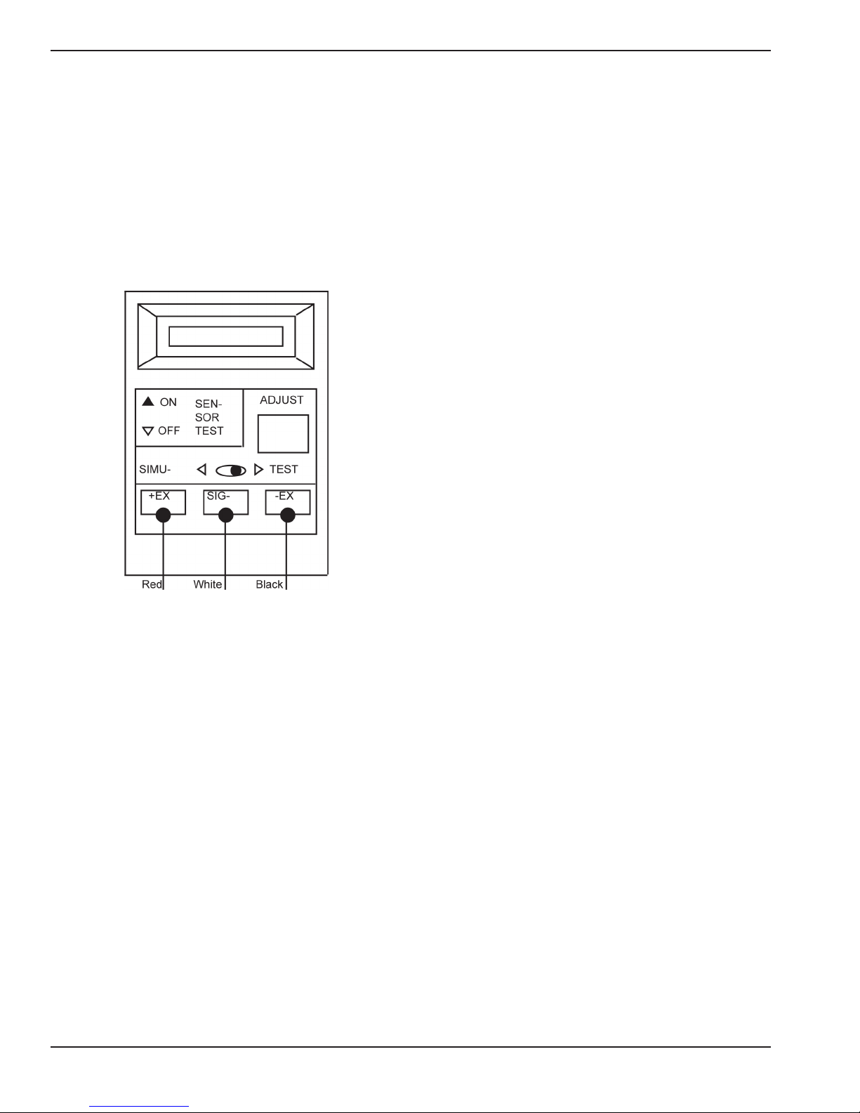
The Kistler-Morse® Test Meter (Figure 2-1) is
designed specically to test Kistler-Morse
®
sensors. If you do not have a test meter,
disregard this section and proceed to TESTING
WITH A DIGITAL MULTIMETER (DMM).
Note
The test meter display indicates a low battery or
behaves erratically when the batteries are weak.
When this occurs, replace the batteries before
testing.
1. See Figure 2-1. Connect the Microcell™
red, white, and black wires to the
corresponding test meter terminals. Place
the Microcell™ on a stable surface.
2. Turn on the power to the test meter and set
the Simulate/Test Switch to the Test
position. Verify the no-load output is
between +25mV and -25mV.
3. Repeat Steps 1 and 2 for each Microcell™.
If the no-load output for any Microcell™ is
outside these specications:
3
A. Proceed to TESTING WITH A DIGITAL
MULTIMETER (DMM) to determine the
resistance values for that Microcell™, and
B. Contact Kistler-Morse
®
for assistance
after determining the resistance values
and before proceeding with installation.
CAUTION
Replace Micrcells™ in packing tubes until ready
to install.
3. Put one DMM lead on the Microcell™ white
wire and the other lead on the black wire.
Place the Microcell™ on a stable surface.
Verify the resistance is within the following
limits:
3” standardized Microcell™ (light blue cover):
8,300Ω - 8,700Ω
2” standardized Microcell™ (dark blue cover):
1,800Ω - 2,200Ω
4. Repeat Steps 2 and 3 for each Microcell™. If
either reading for any Microcell™ is outside
these specications, contact Kistler-Morse® for
assistance before proceeding with installation.
CAUTION
Replace Micrcells™ in packing tubes until ready
to install.
Figure 2-1. Kistler-Morse® Test Meter.
TESTING WITH A DIGITAL MULTIMETER (DMM)
Follow this procedure to test the Microcell™ sets
®
if you do not have a Kistler-Morse
Test Meter or
the readings using the Test Meter were outside the
specications:
1. Set the DMM resistance scale to
accommodate a measured range up to
20,000Ω.
2. Put one DMM lead on the Microcell™ white
wire and the other lead on the red wire. Place
the Microcell™ on a stable surface. Verify the
resistance is within the following limits:
3” standardized Microcell™ (light blue cover):
8,300Ω - 8,700Ω
2” standardized Microcell™ (dark blue cover):
1,800Ω - 2,200Ω
4
CHAPTER 3. MICROCELL™ INSTALLATION
ON VERTICAL COLUMN LEGS
INTRODUCTION
Follow the instructions in this chapter only if
installing Microcells™ on vertical column legs.
This chapter describes the mounting locations,
installation details, and wiring details for
Microcells™ and junction boxes. Follow all
instructions carefully to ensure proper system
operation.
Note
Do not mix different types of Microcells™ on
one vessel. The three types (3” standardized,
3” non-standardized, and 2” standardized) are
not interchangeable.
MOUNTING LOCATIONS
Follow the procedures below to determine and
mark Microcell™ mounting locations prior to
beginning installation. Following these procedures
will ensure optimal system performance. Consult
Kistler-Morse® if special considerations prevent
you from installing Microcells™ at the designated
locations.
MICROCELL™ SETS
BEST PERFORMANCE
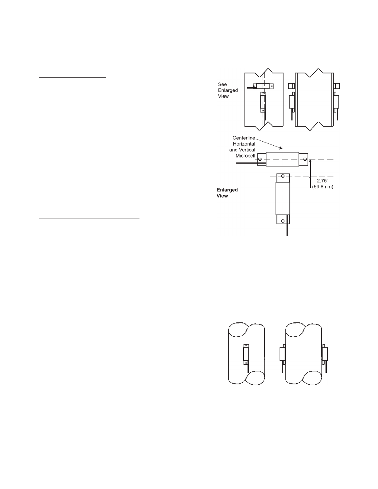
See Figure 3-1. For best performance,
Microcells™ are mounted in a rosette array — a
vertical Microcell™ with a horizontal Microcell™
above it in a “T” conguration. A Microcell™ set
consists of two rosette arrays (four Microcells™
total) mounted on opposite sides of a support leg,
at the same elevation.
Note
Best performance cannot be achieved if:
1. The leg is too narrow for the horizontal
Microcell™ and its environmental cover, or
2. Installation is on round legs.
See STANDARD PERFORMANCE.
Figure 3-1. Microcell™ Rosette Array for
Best Performance.
STANDARD PERFORMANCE
For standard performance, Microcells™ are
mounted vertically. A Microcell™ set consists of
two (2) Microcells™ mounted on opposite sides of
a support leg, at the same elevation.
Figure 3-2. Vertical Microcell™ for
Standard Performance.
5
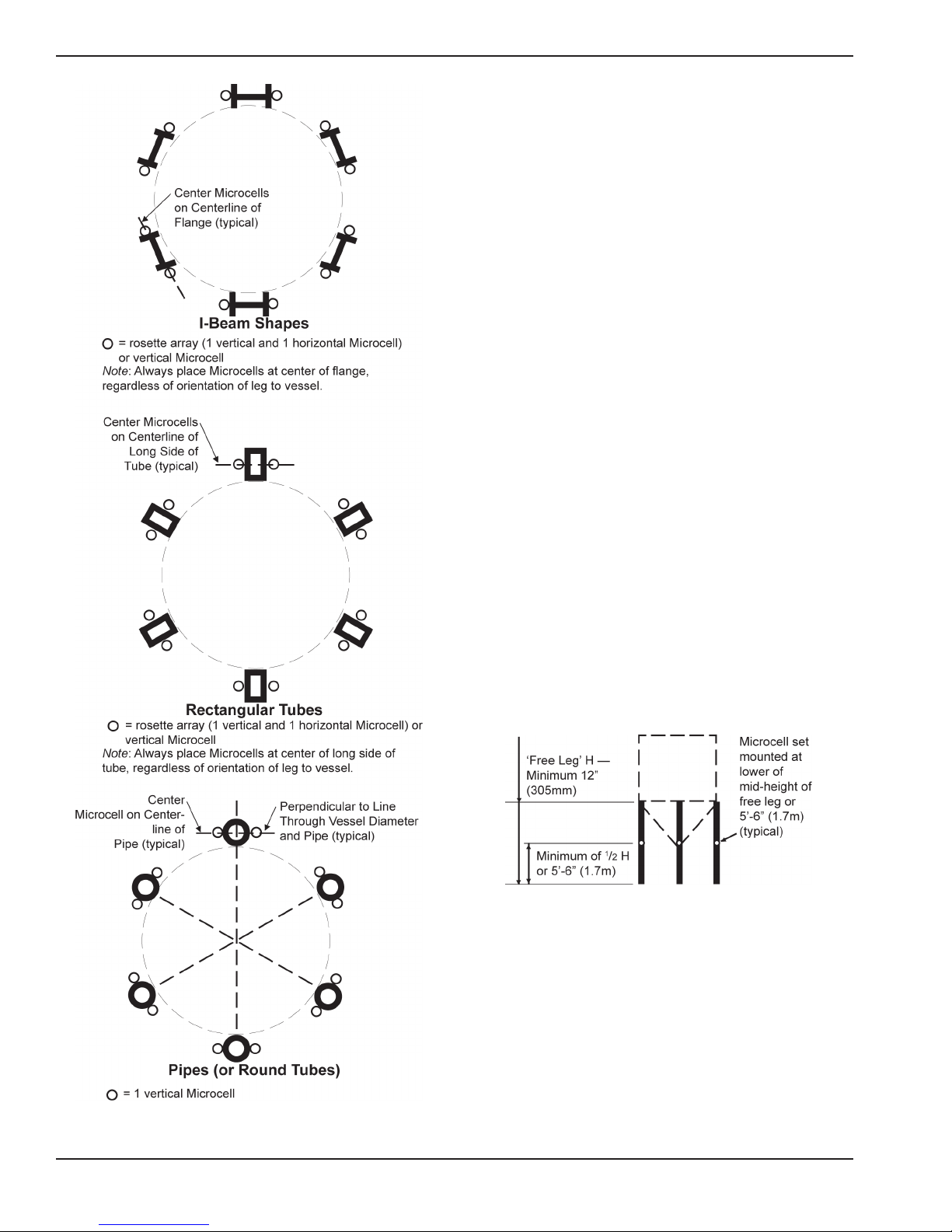
HORIZONTAL DISTRIBUTION OF
MICROCELL™ SETS
Microcell™ sets are placed on each support leg.
Refer to Figure 3-3 for the mounting locations for
each shape.
VERTICAL LOCATION OF MICROCELL™
SETS
Note
Microcell™ locations may be adjusted up to
12 in (305mm) vertically to avoid obstacles. If
adjusting locations, maintain the conguration
of the Microcell™ set (i.e., if one Microcell™ in
the set is moved from its ideal location, move
the other(s) as well).
COLUMN LEGS WITHOUT X-BRACES
See Figure 3-4.
If the free leg distance is between 12 in (305mm)
and 11 ft (3.4m), mount the Microcell™ sets at
mid-height of the free leg.
If the free leg distance is more than 11 ft (3.4m),
mount the Microcell™ sets at 5 ft 6 in (1.7m) above
the foundation.
If the free leg distance is less than 12 in (305mm),
this is a special application situation. Consult
Kistler-Morse® before proceeding further.
Figure 3-4. Vertical Location of Microcell™
Sets for Legs Without X-Braces.
COLUMN LEGS WITH X-BRACES
See Figure 3-5.
If the free leg distance is 12 in (305mm) or more, mount
the Microcell™ sets at mid-height of the free leg.
Figure 3-3. Microcell™ Mounting Arrangements on Legs.
Measure the free leg between the bottom of the bottom
X-brace or horizontal brace and the top of the
foundation.
6
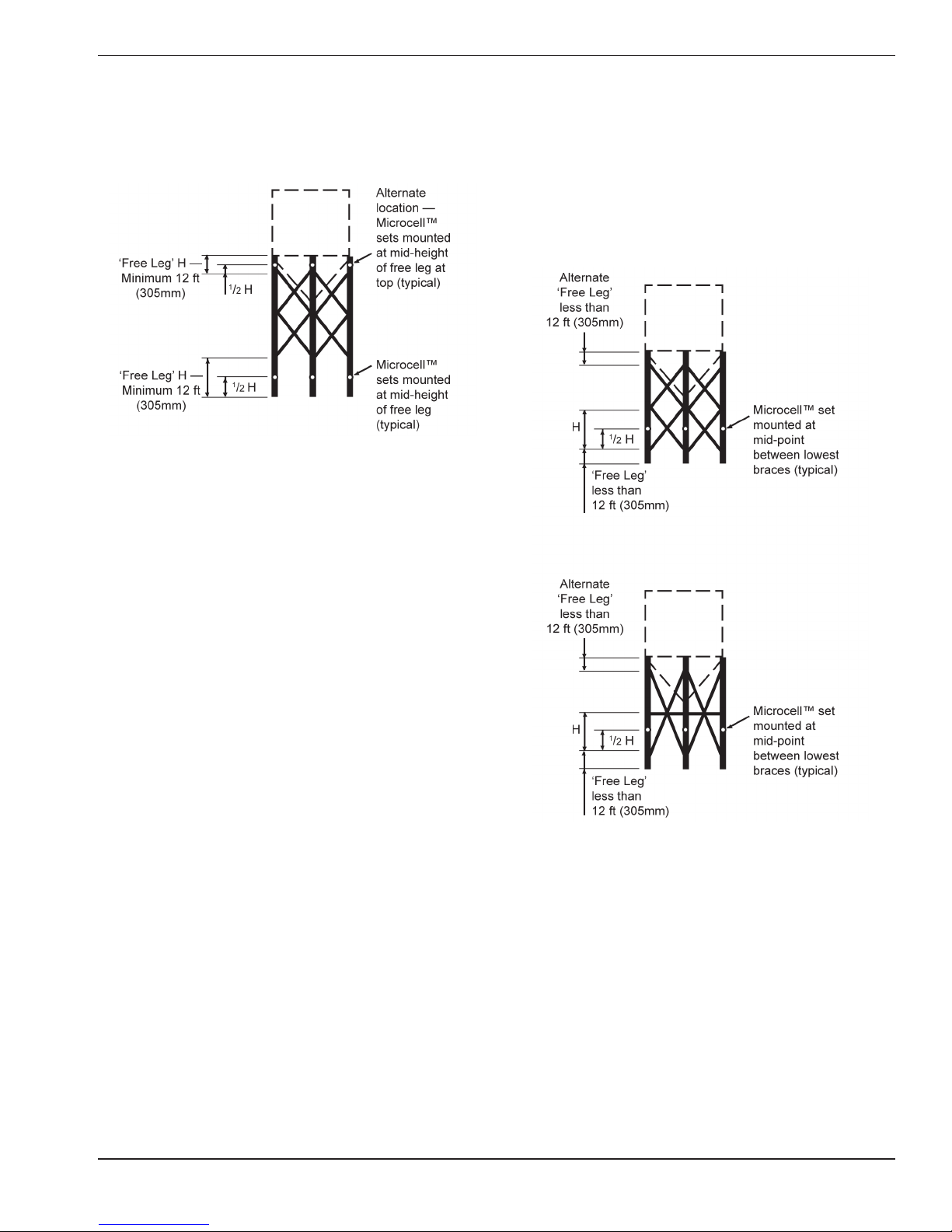
For an alternate location, measure the free leg
between the top of the top X-brace or horizontal
brace and the beam supporting the vessel.
Figure 3-5. Vertical Location of Microcell™
Sets for Legs With Braces and with Free
Leg Greater Than 12 in (305mm).
See Figure 3-6. If the free leg distance is less than
12 in (305mm), mount the Microcell™ sets at the
mid-height between the lowest braces. When
mounting between the braces, insulation around
the adjacent braces is required for best
performance. This insulation will reduce the effect
of sun-induced stresses on the support metal.
Figure 3-6. Vertical Location of Microcell™
Sets for Legs With Braces and with Free
Leg Less Than 12 in (305mm).
7
INSTALLING MICROCELL™ SETS
Note
1. Use lubricating uid (Relton RapidTap®
Heavy Duty Cutting Fluid or equivalent)
when drilling and tapping.
2. Drilling and tapping instructions assume
metal thickness greater than ¾” (19mm).
If the thickness is less, drill all the way
through the metal and tap until cutting
complete threads through the other side.
Minimum metal thickness is 0.1875” (5mm),
which provides six thread engagement.
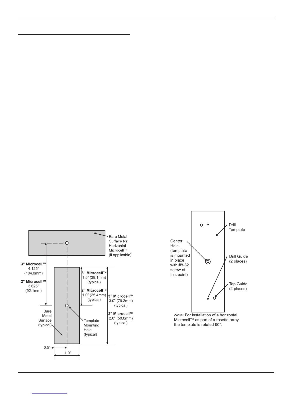
SURFACE PREPARATION
1. See Figure 3-7. At the center of the
vertical Microcell™ mounting location, drill a
¾” (19mm) deep hole with the #29 drill bit.
This produces the template mounting hole.
Repeat for the horizontal Microcell™
(if applicable).
2. See Figure 3-7. Mark the surface preparation
area for the vertical Microcell™ and horizontal
Microcell™ (if applicable).
3. Attach the coarse grit sandpaper to the
grinder. Remove heavy paint and rust with
the grinder until a bare metal surface is
achieved. Due to the use of coarse grit, the
resulting surface is somewhat coarse.
4. Replace the coarse grit sandpaper with the
ne grit sandpaper. Grind until the surface(s) is
completely down to bare metal and smooth to
the touch.
Note
The Microcell™ must be mounted against
smooth, bare metal. Remove all paint and rust
from the area where the Microcell™ is to be
fastened.
DRILL AND TAP
1. Using the #8-32 tap, thread the template
mounting hole for the vertical Microcell™
(drilled during Surface Preparation) to a
minimum
Remove any burrs from the hole.
2. See Figure 3-8. Position the drill template
so the center hole lines up with the template
mounting hole.
3. Fasten the drill template to the template
mounting hole through the center hole, using
the captive #8-32 socket head cap screw. Use
a level to ensure correct orientation.
4. Using the #29 drill bit, drill two ¾” (19mm)
deep holes in the leg through the template drill
guides.
5
/8” (16mm) depth, full threads.
Figure 3-7. Prepared Mounting Surface.
Figure 3-8. Drill and Tap Template.
8

5. Loosen the screw securing the template and
rotate the template until the two tap guides line
up with the drilled holes. Push the #8-32 tap
into one of the tap guide holes to align the
template. Retighten the screw securing the
template.
6. Using the #8-32 tap, thread the two holes
through the template tap guides. Tap to a
minimum
5
/8” (16mm) depth, full threads.
Remove the template from the leg.
7. If installing a rosette array, repeat Steps 1
through 6 for the horizontal Microcell™.
8. Remove burrs from all the holes created.
MOUNTING MICROCELL™ SETS
CAUTION
Do not install Microcells™ in the rain. Do not
trap moisture under the environmental cover.
1. Wipe down a 5 in by 2¼ in (127mm by 57mm)
surface, centered on the template mounting
hole, with degreaser. This cleans the bare
metal and adjacent mounting surface for the
environmental cover.
2. Apply a thin coat of Kistler-Morse
inhibitor to the bare metal surface for the
vertical Microcell™.
CAUTION
Do not apply rust inhibitor beyond this area, or
the environmental cover will not adhere
properly.
3. Connect the Microcell™ red, black, and white
wires to the corresponding terminals on the
®
Kistler-Morse
Test Meter. Turn on the power
to the Test Meter and set the Simulate/Test
Switch to the Test position.
Note
If a Kistler-Morse® Test Meter is not available,
refer to Appendix C (Alternate Method for
Checking Output) before proceeding.
®
rust
Note
3” Microcells™ for vertical and horizontal
installation are slightly different. 3” Microcells™
for horizontal installation are labeled
“Horizontal.” 3” Microcells™ for vertical
installation are not labeled.
CAUTION
For proper installation, tighten each screw until
the T-handle driver exes in torsion ¼ turn past
the point where the screw stops turning.
Repeat this exing procedure several times to
ensure the screw is tight. When both screws
are tight, the voltage must be in the range
-100mV to +100mV. Follow the procedure in
Steps 5 through 7 to achieve this goal.
5. Using the T-handle driver, slowly tighten the
top screw. While turning the T-handle driver,
monitor the test meter carefully. If the
voltage goes outside the range -100mV to
+100mV while tightening, stop immediately
and evaluate the following:
A. If the voltage jumped outside the range
-100mV to +100mV, it may indicate a burr
or rough surface. Remove the screws
holding the Microcell™ to the leg. Check
for and remove burrs and surface
roughness (refer to SURFACE
PREPARATION for removing surface
roughness). Repeat Steps 1through 5.
B. If the voltage gradually moved outside the
range -100mV to +100mV, slowly loosen
the screw until the voltage is within range
again and proceed to Step 6.
6. Repeat Step 5 for the bottom screw. If the
voltage is outside the range -100mV to
+100mV, attempt to bring the reading within
range by loosening the screw being torqued,
tightening the other screw, or some
combination of loosening and tightening. If
you have difculty staying within the range, try
turning each screw ¼ turn at a time until both
screws are tightened.
4. With the cable end down, align a vertical
Microcell™ with its mounting holes. Fasten the
Microcell™ loosely to the leg using the two
#8-32 x
5
/8” socket head cap screws and
washers. Do not tighten the screws. If the
voltage goes outside the range -100mV to
+100mV, immediately loosen the screw(s).
9
Note
If the following occurs while tightening screws,
check Microcell™ resistance using a DMM
(described in Problem 1 in Chapter 6):
A. Voltage does not change or changes less
than 25mV as you turn a screw, or
B. Voltage changes randomly as you turn a
screw (i.e., not in a consistent direction).
7. To complete installation, ensure that both
screws are tightened until the T-handle driver
exes in torsion, ¼ turn past the point where
the screw stops turning, with this exing
procedure repeated several times to ensure the
screw is tight, and the voltage is in the range
-100mV to +100mV.
8. Repeat Steps 1 through 7 for the horizontal
Microcell™ (if applicable).
9. Prior to installing the environmental cover(s),
ensure the mating surface(s) on the leg is free
of dirt and grease. Reclean if necessary, being
careful not to remove the rust inhibitor on the
bare metal.
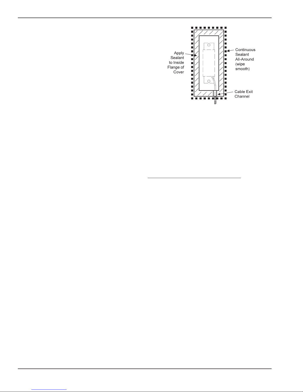
10. See Figure 3-9. Apply a generous bead of
sealant to the inside ange of the
environmental cover. Add extra sealant to the
cable exit channel.
A. Align the environmental cover over the
installed Microcell™, with the cable through
the cover’s exit channel.
B. Press the cover against the web,
squeezing out the sealant around the
edges. Be careful not to squeeze too
much sealant out.
C. Use your nger to smooth the sealant
around all edges and joints, eliminating
areas where moisture may pool, especially
along the top edge. Verify the sealant
forms a continuous, watertight seal. Ensure
the cable exit channel is completely sealed.
D. Repeat Step 10 for the horizontal
Microcell™ (if applicable).
CAUTION
Only use Sikaex 1A polyurethane sealant or
Dow Corning RTV 738 or RTV 739. Other
sealants may contain acetic acid, which is
harmful to sensors and electronics.
Figure 3-9. Environmental Cover.
11. If you created any holes that go completely
through the support metal, spread sealant
(Sikaex 1A polyrethane sealant or Dow
Corning RTV738 or RTV 739) over the open
holes. Use your nger to press sealant into
each hole.
MOUNTING JUNCTION BOX
MOUNTING LOCATION
Each junction box can be wired to a maximum of
two Microcell™ sets (four Microcells™ total):
1. Microcell™ rosette arrays - the four
Microcells™ on a support leg (two sets, each
cosisting of a vertical and a horizontal
Microcell™) are wired to one junction box.
2. Vertical Microcells™ - one junction box can be
wired to Microcells™ from two support legs
(two Microcells™ on each support leg) if the
legs are sufciently close to each other to allow
the Microcell™ cables to reach.
See Figure 3-10. Locate the junction box on the
support leg web or on a brace. Vertically, locate
junction boxes at a convenient height,
approximately 4 ft (1.2m) from the ground. The
exact location of the junction box is not critical,
but ensure you have sufcient cable length and
that a drip loop will be formed by the Microcell™
cables when wired to the junction box.
10
 Loading...