

Page 1
Load Disc 3xi/LD3xiC
Installation Manual
CAUTION
It is essential that all instructions in this
manual be followed precisely to ensure
proper operation of the equipment.
97-1137-02
Rev F
July 2003
Page 2

NOTICE
The content of this document is the intellectual property of Kistler-Morse Corporation.
Any reproduction or translation of this document without the written authorization of a
Kistler-Morse corporate officer is prohibited.
CAUTION
Follow these rules if welding is done on the vessel after installation of the Load Disc.
The electrical current of the welder may pass through the Load Disc, causing damage to the
transducer and possibly to the signal processor. To avoid damage, follow these precautions:
1. Disconnect the Load Disc cables from the signal processor.
2. Ground the welder as close to the welding joint as possible. The welding ground must be
between the Load Disc and the weld joint to prevent the welding current from going through the
Load Disc to earth ground.
Note
High temperatures can damage the Load Disc. If you are welding in the vicinity of a
Load Disc, monitor the temperature of the metal adjacent to the Load Disc. If it becomes too hot to
touch, stop welding immediately and remove the Load Disc before continuing. Prior to reinstalling
the Load Disc, verify that no damage has occurred by referring to the measurement procedures in
Troubleshooting, Appendix C.
Page 3

Table of Contents
Table of Contents
Introduction....................................................................................................i
Welcome ........................................................................................................................................................... i
About this manual ............................................................................................................................................i
Manual Conventions ................................................................................................................................. i
Specifications ................................................................................................................................................... ii
Chapter 1. Description of the Load Disc............................................... 1-1
Introduction .................................................................................................................................................. 1-1
Description of Measurement System ...................................................................................................... 1-1
Applications Descriptions ....................................................................................................................... 1-1
Installation Option Descriptions ................................................................................................................... 1-2
Universal Top Adaptor Plate ................................................................................................................. 1-2
Leveling Top Plate Adapter ................................................................................................................... 1-3
Anyadapter Plate ................................................................................................................................... 1-3
Leveling Base Adapter Plate .................................................................................................................. 1-4
LD3xiC Assembly Option ...................................................................................................................... 1-4
Chapter 2. Preparing for the Load Disc Installation ........................... 2-1
Check Shipment ............................................................................................................................................ 2-1
Load Disc Order Items ............................................................................................................................. 2-1
Visual Check ............................................................................................................................................ 2-1
Measuring Sensor Output ............................................................................................................................ 2-2
Prepare Installation Equipment ..................................................................................................................... 2-3
Installation Equipment Needed .............................................................................................................. 2-3
Vessel Preparation......................................................................................................................................... 2-3
Factors Affecting Performance ..................................................................................................................... 2-4
Chapter 3. Mounting the Load Disc ...................................................... 3-1
General Information ....................................................................................................................................... 3-1
LD3xi/LD3xiC General Installation ................................................................................................................. 3-2
Leveling and Shimming ................................................................................................................................. 3-5
Leveling/Shimming using Universal Top Adapter Plate .......................................................................... 3-5
Leveling/Shimming using Leveling Top Adapter Plate ........................................................................... 3-6
Leveling/Shimming using Leveling Base Adapter Plate .......................................................................... 3-6
Leveling/Shimming using Anyadapter Plate ........................................................................................... 3-6
Junction Box Mounting and Wiring.............................................................................................................. 3-7
Trim Box Mounting and Wiring .................................................................................................................. 3-10
Appendix A: Contact Information ................................................................................. A-1
Appendix B: System Calibration ................................................................................... B-1
Appendix C: Troubleshooting ........................................................................................ C-1
Appendix D: Technical Drawings.................................................................................. D-1
i
Page 4

Table of Contents
PB
Page 5

Introduction
Introduction
This chapter describes the organization, manual conventions,
and provides specification information .
Welcome
About this manual
This manual describes the installation of the Load Disc 3xi/3xiC load cell and
its various hardware options. It includes procedures for leveling and shimming of the vessel if it is neccessary. Instructions for wiring the load cell to
the junction boxes and wiring the junction boxes together and to the signal
processor are also included. Refer to the signal processor manual for specific
information on wiring the junction boxes to the signal processor.
Contact KM at 1-800-426-9010 if you have any questions regarding the
installation. For outside the USA and Canada, call 425-486-6600.
The chapters are organized in the following way:
Chapter 1: Description of the Load Disc 3xi/3xiC
Chapter 2: Preparing the Load Disc 3xi/3xiC for Installation
Chapter 3: Mounting the Load Disc 3xi/3xiC
Appendix A through D include contact info, system calibration, troubleshooting charts and technical drawings (TI’s).
Manual Conventions
Three kinds of special explanations appear throughout the manual —
Warning , Caution and Note. The format and significance of each is
defined below:
WARNING
Possible danger to people. Injury may result if this information is
ignored.
CAUTION
Possible risk to the product. The Load Disc or other equipment may be
damaged if this information is ignored.
Note
Contains additional information about a step or feature critical to the
installation or operation of the Load Disc.
i
Page 6

Specifications
Introduction
LD3xi
Mechanical
Compression: 3 x rated load
Tension: 1 x rated load
Shear (capacity 220 lbs -2200 lbs): 0.5 x rated load
(capacity 5500 lbs): 0.25 x rated load
Functional Integrity: 1.5x rated load (compression)
Electrical
Excitation Voltage - Operating Range: 5-15 VDC
Recommended Supply Voltage: 10 VDC
Maximum Current: 16mA @ 10 VDC excitation (0o F)
Output Resistance: 700 ohms +/- 2%
Output
Non-linearity/Hysteresis combined: 0.03% standardized output
Return to Zero over 30 min: 0.026% standardized output
Creep over 30 min: 0.028% standardized output
Creep over 20 and 30 min: 0.008% standardized output
Zero Balance: 1% standardized output
Rated Output: 2 mV/V +/-0.1%
LD3xiC/LD3xiMJ
Mechanical
Compression: 3 x rated load
Tension: 1 x rated load
Shear: 0.5 x rated load
Functional Integrity: 1.5x rated load (compression)
Electrical
Excitation Voltage - Operating Range: 5-15 VDC
Recommended Supply Voltage: 10 VDC
Maximum Current: 16mA @ 10 VDC excitation (0
Output Resistance: 700 ohms +/- 2%
Output
Non-linearity/Hysteresis combined: 0.03% rated output
Return to Zero over 30 min: 0.026% rated output
Creep over 30 min: 0.028% rated output
Creep over 20 and 30 min: 0.008% rated output
Zero Balance: 1% rated output
Rated Output: 2 mV/V +/-0.1%
o
F)
Environmental
Temperature Range - Standard: 14o to 104o F (-10o to 40o C)
Temperature Zero Shift: 0.0013%/
Temperature Sensitivity Change: 0.00094% /
Storage Temp Range: -4
o
to 176o F (-20
o
F (0.0024%/oC)
o
F (0.0017% /o C)
o
C to 80oC)
Humidity: 100%
Physical
Construction: 17-4 PH 900 stainless steel
Connector (optional): 6P rated sealed 5-conductor,
12mm male receptacle
Cable Length: 16ft. (5 m) with tinned pigtail termination
Rating: IP68
Shipping Weight: 5 lbs (2.3 kg)
(100h at 1m water column)
Environmental
Temperature Range - Standard: 14o to 104o F (-10o to 40o C)
Temperature Zero Shift: 0.0013%/
Temperature Sensitivity Change: 0.00094% /
Storage Temp Range: -4
o
to 176o F (-20
o
F (0.0024%/oC)
o
F (0.0017% /o C)
o
C to 80oC)
Humidity: 100%
Physical
Construction:
sensor: 17-4 PH 900 stainless steel
cage: 304 stainless steel
Cable Length: 16ft. (5 m) with tinned pigtail termination
Rating: IP68 (100h at 1m water column)
Shipping Weight: 18.7 lbs (8.5 kg)
Approvals: CE, OIML R60
ii
Page 7
Chapter 1. Description
Chapter 1:
Description of the Load Disc
This chapter describes the Load Disc 3xi/3xiC/3xiMJ
Compression Load Cell and its installation options.
Introduction
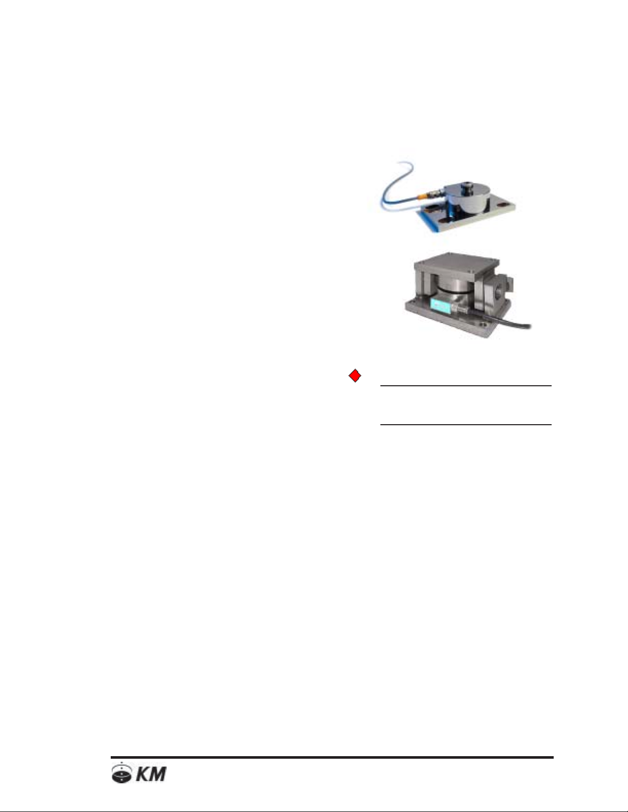
The Load Disc 3xi/3xiC/3xiMJ is a low profile load cell that is bolted to both
the support surface and the vessel supports, and is used to measure the
weight of materials in vessels and tanks. The sealed, stainless steel construction--IP68 rated unit with an optional NEMA-6P watertight cable system and
cable entry–makes the LD3xi/3xiC/3xiMJ ideal for use in high-pressure wash
Figure 1-1:
LD3xi Compression Load Cell
with optional NEMA-6P cable
system
down and occasionally submerged environments. The LD3xi/LD3xiC/3xiMJ
offers system performance accuracy of 0.03%.
The low-profile design for low clearance installations also keeps the vessel’s
center of gravity low and stable. Vessel tipping, walking or overturning while
agitating is eliminated. Installation and setup is simplified with less hardware.
No external vessel hold-downs are necessary, even in areas of high wind or
seismic activity. There are no moving parts that can wear out or require
replacement.
weight/4
weight/4
LD3xi/
LD3xiC
(x4)
junction box
signal
processor
weight/4
weight/4
Signal
transmission/
Serial Output
Setpoints for
signaling a
change in staus,
such as high and
low alarms
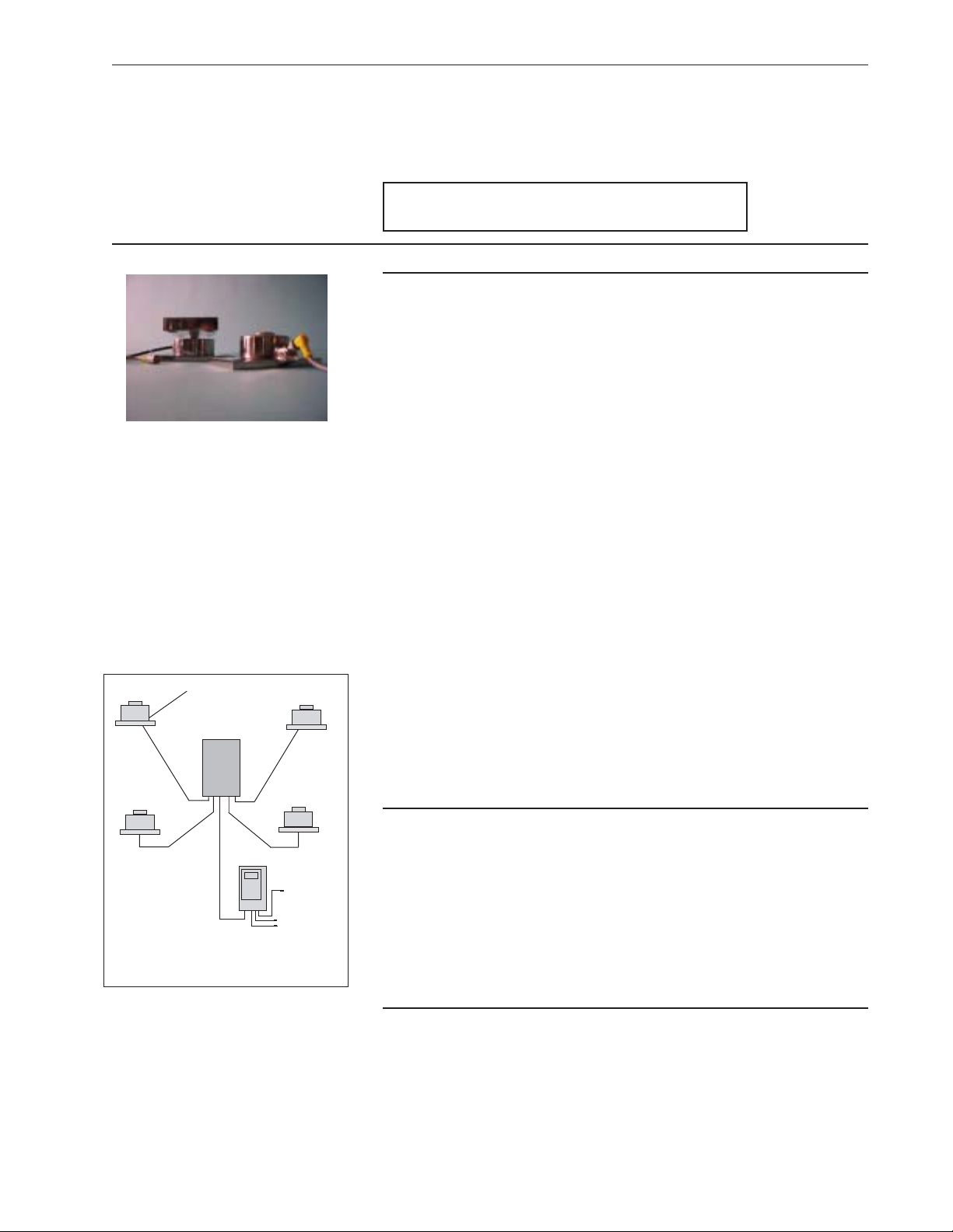
Figure 1-2:
General installation layout for LD3xi/
LD3xiC using a junction box.
In bakery, pasta, confectionary and spice processing to resins, concrete/
aggregate, sand, pulp, minerals and other dry-to-wet operating conditions,
the LD3xiC offers very specific advantages not available in most higher
priced load cells. Standards include a tough “cage” mounting fixture into
which the 17-4 stainless steel LD3xiC cell securely locks in place. Since the
LD3xiC cell can be loaded before or after the tank is installed onto the “cage”
fixture, you have more flexibility in mounting procedures. If ever the cell
needs to be replaced, it can be unloaded without having to remove the
“cage” fixture itself. The LD3xiC is available in virtually all popular weight
capacities from 220 lbs to 22,000 lbs. and is easy to specify due to identical
dimensions and price.
General Description of Measurement System
The deflection of the load cell by the vessel weight is measured by the foil
gage sensor, which is entirely sealed within the watertight cavity of the
transducer. The sensor converts the deflection into an electrical signal which is
directly proportional to the increase or decrease of the vessel contents.
Material movement and changes in material repose will not affect the accuracy
of the system. Accurate weight information is then sent to a signal processor
for display, information transmission and storage (See Figure 1-2).
Applications Description
The watertight design of the load cell makes it ideal for measuring bulk
material in the sanitary and clean-in-place environments. It is particularly
suitable for use on mixing and blending vessels, surge hoppers, and agitated
vessels. Rugged, solid, bolt-in-place mounting assures vessel stability in
outdoor storage vessels with gussets or legs used in all process industries.
1-1
Page 8
Installation Option Descriptions
Chapter 1. Description
This section will briefly describe the following hardware options:
Universal Top Plate Adapter, Leveling Top Plate Adapter,
Anyadapter Plate and Leveling Base Adapter Plate.
As well as the LD3xiC Load Cell configuration.
See Chapter 2 and 3 for more specific installation instructions and
refer to the TI drawings located in Appendix D.
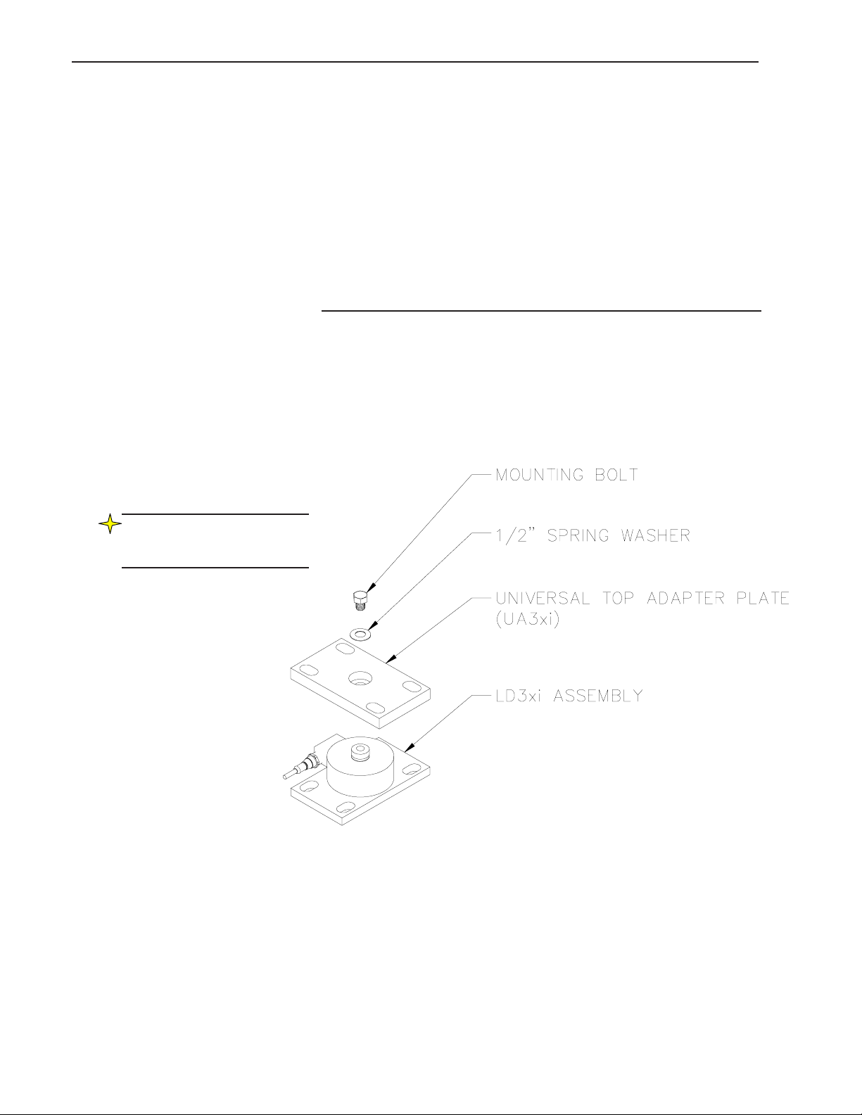
Universal Top Adapter Plate
This option consists of the Universal Top Adapter Plate, spring washer and a
hex head bolt. The adapter plate attaches to the load disc with the bolt and
washer. The adapter plate then bolts to a vessel gusset or a flat plate welded
to the vessel leg, using customer-supplied hardware.
Note: Accomodates up to three
degrees of tilt in the floor or
vessel legs.
1-2
Page 9
Chapter 1. Description
Leveling Top Plate Adapter
This option consists of the Universal Top Adapter Plate, a hex head bolt,
spherical washer set and jam nuts. The adapter plate attaches to the load disc
with the hex bolt and hardware. The adapter plate then bolts to a vessel gusset or
a flat plate welded to the vessel leg, using customer-supplied hardware.
This hardware arrangement allows 360 degree movement of the top plate and
angular misalignment of up to 3 degrees. Additionally, there is a leveling feature
that allows vertical height adjustments. This arrangement also incorporates a
locking-jam nut to insure the height remains unchanged.
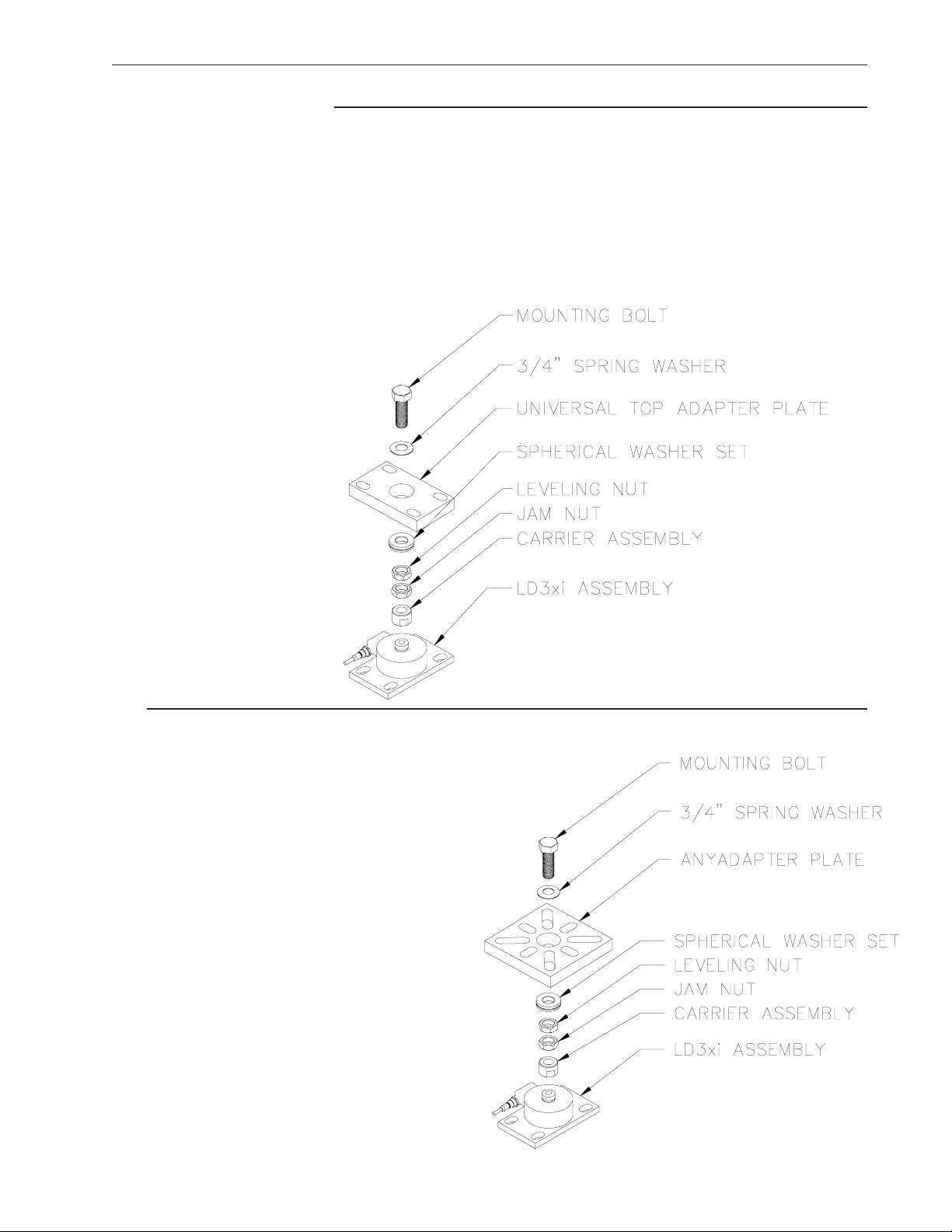
Anyadapter Plate
This option consists of the unique Anydapter Plate which has a
universal bolt pattern (to fit a variety of vessel leg flanges), and a hex
head bolt. The plate attaches to the load disc with the bolt and washers.
The Anyadapter plate then bolts to a vessel gusset or a flat plate
welded to the vessel leg, using customer-supplied hardware.
This hardware arrangement allows 360 degree movement
of the top plate and angular misalignment of up to 3
degrees. Additionally, there is a leveling feature that
allows vertical height adjustments. This arrangement
also incorporates a locking-jam nut to insure that the
height remains unchanged.
1-3
Page 10
Note:
Adapter plate not shown in
illustrationat right.
This kit requires an adapter
plate for proper installation.
Chapter 1. Description
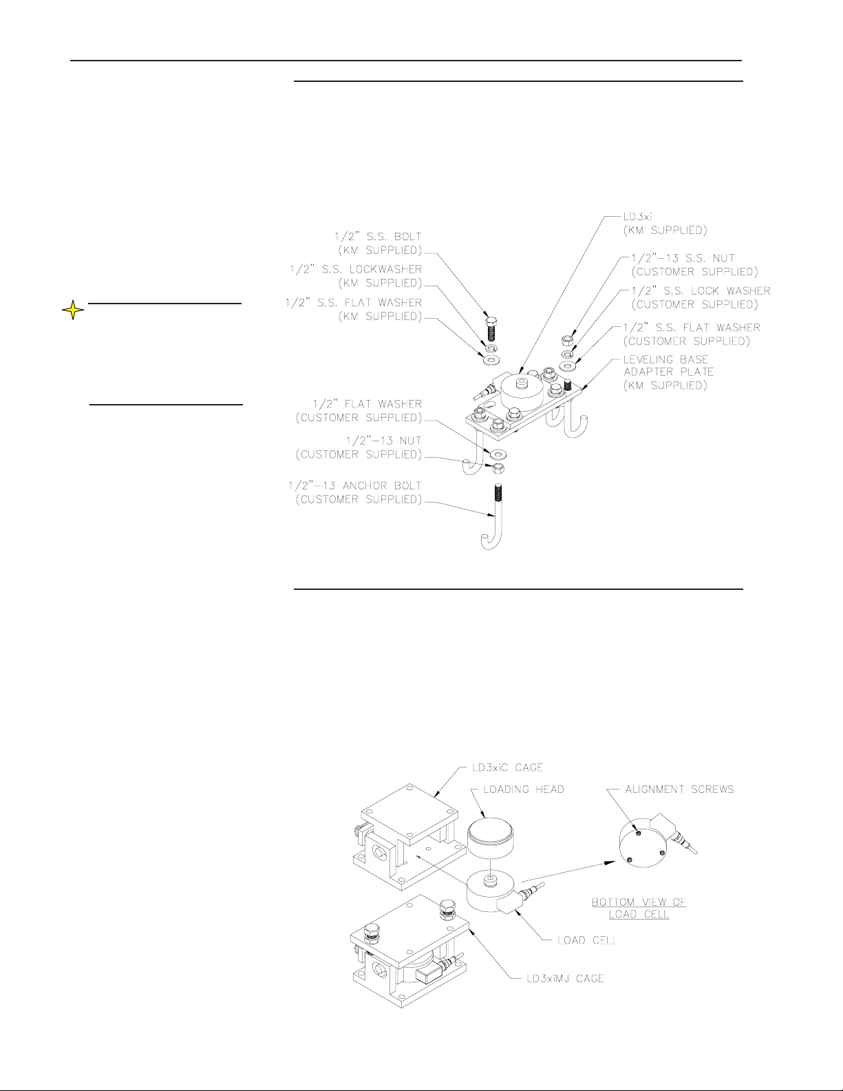
Leveling Base Adapter Plate
This kit consists of a Leveling Base Adapter Plate and four hex bolts, four flat
washers, and four lock washers. The LD360S bolts onto the leveling base
adapter plate. This plate rests on four leveling nuts and washers screwed onto
anchor bolts installed in the foundation. By turning the leveling nuts, the height
of the load discs and thus the vessel, can be adjusted for proper load distribution.
LD3xiC/3xiMJ Load Cell Assembly
This unit consists of the LD3xiC/3xiMJ load cell assembly (load cell and installed
set screws) and a cage assembly. The load cell has the loading head on top and
they both slide into the cage assembly. They are held in place with three set
screws. The set screws are pre-installed into the load cell at the factory. The load
cell assembly slips down into the holes of the cage assembly. (The LD3xiC
assembly does not include jacking bolts, the LD3xiMJ does include jacking
bolts.)
1-4
Page 11

Chapter 2. Pre-Installation
Chapter 2:
Preparing for the Load Disc Installation
This chapter describes the pre-check procedures for the LD3xi/LD3xiC.
Checking the load discs before installation will ensure properly
working equipment that will provide accurate monitoring of
vessel contents.
Check Shipment
Perform the following prior to installing the Load Disc:
Check Load Disc Order Items
The following items are included with a typical order for each vessel
(quantities dependent on application):
LD3xi/LD3xiC Load Cell
Junction Boxes or molded junctions
Top or Bottom Hardware (LD3xi only)
If any items are needed, contact KM before proceeding. Substituting
parts without KM approval may cause system problems and will void
the warranty.
Visual Check
Visually inspect all equipment in the order — including Load Discs,
junction boxes, and signal processors — to verify they have not been
damaged during shipment. If any item has been damaged, contact KM
for a replacement.
2-1
Page 12
Chapter 2. Pre-Installation
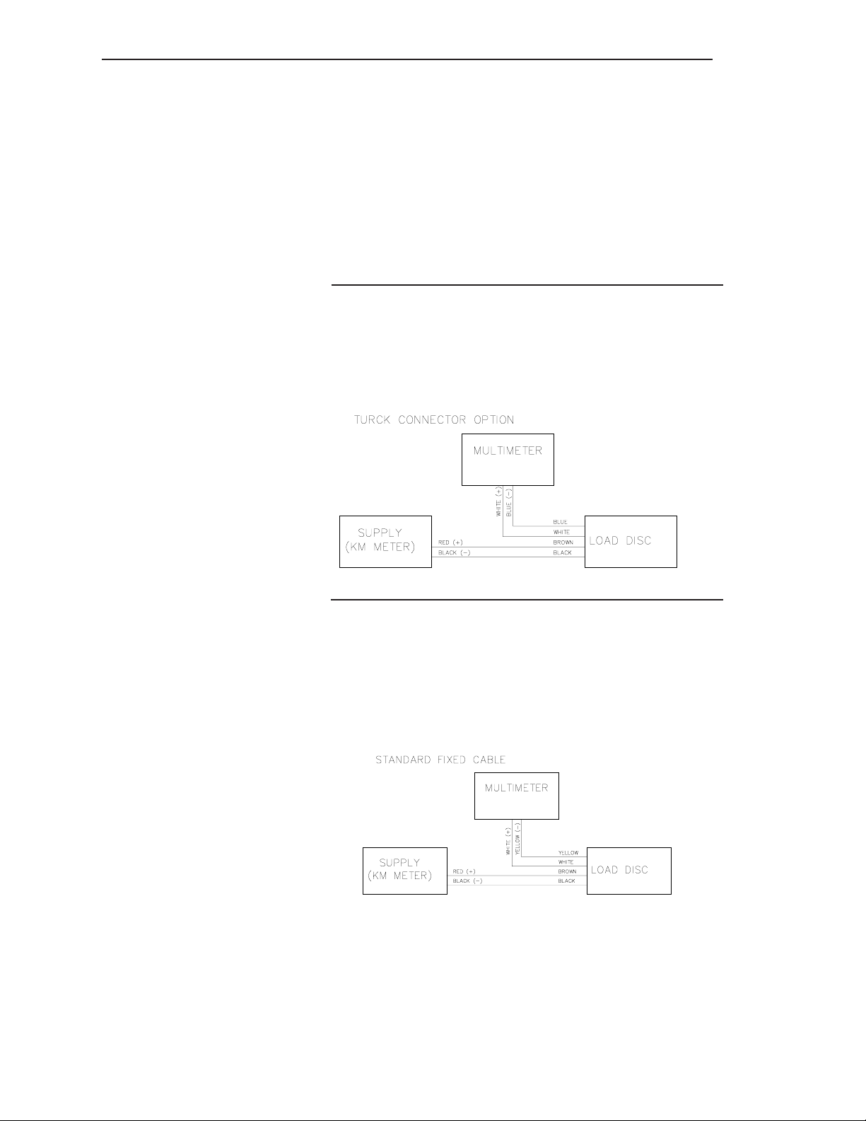
Measuring Sensor Output
To measure the output of the LD3xi/LD3xiC, the sensor needs to
have an excitation voltage applied to it from a signal processor, a DC
voltage generator, or a KM test meter.
To use the excitation from the KM Test Meter, put the switch in
the simulate position and wire the positive to the red position
and the negative to the black position.
Turck Option
The excitation would be applied to the excitation wires or the quick
disconnect cable, brown (positive) and black (negative). The
millivolt signal would be measured with a multimeter on the output
wires, white (positive) and blue (negative).
Standard Fixed Cable
The excitation would be applied to the excitation wires of the
standard fixed cable, red (positive) and black (negative). The
millivolt signal can be measured on the output wires, white (positive)
and Yellow (negative).
2-2
Page 13

Prepare Installation
Equipment
(Customer Supplied)
Chapter 2. Pre-Installation
The following equipment is needed to install Load Discs:
Lifting equipment
Tape measure
Level
Pry bar
Marking pen
Wrenches
ASTM A-325 bolts or anchor bolts (or equivalent
strength), lock washers, and flat washers to
secure Load Disc to vessel support or
foundation (if applicable)*
Signal processor
Shims (if applicable)
Grout (if applicable)
Note: KM recommends the use
of a trim box for applications
which need to be “certified for
trade”.
Vessel Preparation
Digital Multimeter (FLUKE™ or equivalent)
* See TI drawings in Appendix D for the appropriate bolt size.
There are two aspects to successful use of Load Discs — properly
functioning Load Discs and appropriate vessel support
characteristics. Review the following list of error sources, and make
the recommended corrections before you install the Load Discs:
• An inadequate vessel foundation can allow excessive
movement. Ensure the foundation is concrete or steel.
• Hidden load-bearing structures, such as discharge chutes
or plumbing supported by the floor, can reduce loads on
the vessel supports. Install flexible couplings to minmize
this problem.
• Cross-connecting structures, such as catwalks and
manifolds, can transfer loads from adjacent vessels.
Install slip joint or flex couplings to minimize this
problem.
• Shock loads can damage the Load Disc. Install protective
barriers or stops to prevent vehicles from hitting the
vessel supports.
2-3
Page 14
Chapter 2. Pre-Installation
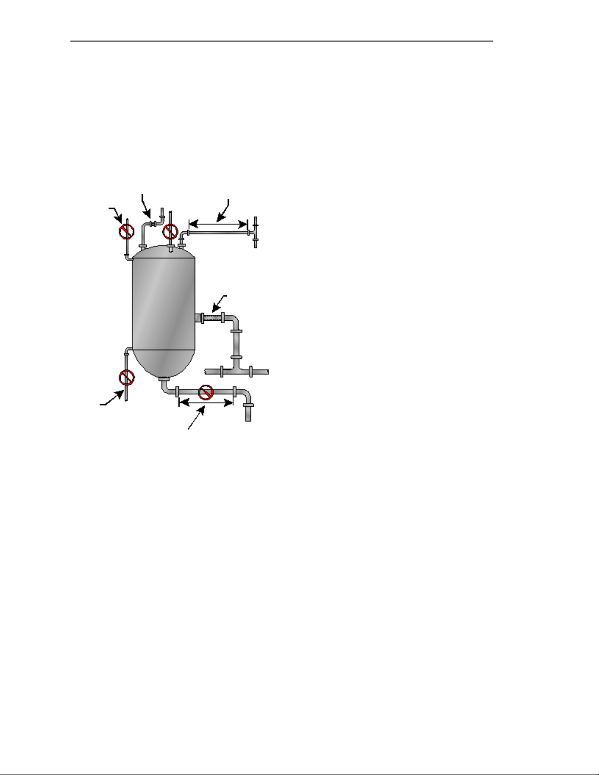
Factors that affect Performance
An independent, isolated vessel with no connection to any other vessel
or adjacent structure provides the most accurate results for a weight
measurement system. Examples of this type of application are floor scales
and truck scales. Connections to other vessels or structures affect
accuracy because the transducers interpret strain changes caused by the
connecting structures as being caused by changes in the material weight.
No horizontal run
No horizontal run
Flex coupling
Horizontal run too short for crosssectional area of pipe
Horizontal run length is ok for
cross-sectional area of pipe
Flex
Some typical causes of error related to
connecting structures and, where applicable,
methods for reducing the errors follow:
• Catwalk
• Hidden load bearing members
• Vessel goes through roof
• Tripper conveyors or deck plating
• Rigid piping connection between vessel and
another adjacent structure
• Poor Foundation
• Flexible Structure
• Uneven Loading
Figure 2-1:
Examples of typical causes of error.
2-4
Page 15

Chapter 3. LD3xi/LD3xiC Mounting
Chapter 3: Mounting the Load Disc
This chapter describes installation and wiring of the
LD3xi/LD3xiC and junction boxes. Follow all instructions
carefully to ensure proper operation of the system.
General Information
The load disc has a variety of mounting hardware options that
accommodate almost all possible applications. These general requirements apply to all applications:
• Ensure the surfaces where the baseplates bolt down onto are
clean, smooth, flat, and level, with less than 1° of slope in any
direction.
• Ensure vessel legs/gussets are clean, smooth, flat, and level,
with less than 1° of slope in any direction.
CAUTION: If you
need to raise the
vessel or one vessel
leg after installation,
loosen the bolts on all
Load Discs to prevent
overloading.
• Position load disc so the cable cannot be snagged or chafed and
can be easily routed to the junction box.
• When raising the vessel for load disc installation, use proper
support to prevent the vessel from tipping or falling.
• During installation, carefully distribute the load to ALL load
discs evenly. PLACING THE LOAD ON ANY ONE LOAD DISC
MAY CAUSE DAMAGE.
• Hardware and Bolts —
1. All bolts and hardware to attach the Load Disc to the vessel
and to the foundation are customer-supplied,
ASTM A-325 or equivalent. (See TI drawings Appendix D)
2. Use specified hardware and bolt sizes. Using other than the
specified hardware can either reduce strength or overstress
the load disc during installation, voiding the warranty.
3. All bolts are kept loose until shimming and leveling is
complete.
• Securing LD3xi/LD3xiC after Leveling/Shimming —
Once the weight distribution criteria has been satisfied
through leveling and/or shimming, complete the installation by
tightening the required bolts for your application.
3-1
Page 16
Chapter 3. LD3xi/LD3xiC Mounting
LD3xi/LD3xiC
General Installation
This section describes the installation procedures for the following
hardware options:
Universal Top Plate Adapter, Leveling Top Plate Adapter, Anyadapter
Plate, Leveling Base Adapter Plate as well as the LD3xiC.
1. Prior to installing the load cell, verify that they are the correct
capacity for your application by reviewing the information on
the label.
2. Measure the load cell voltage output. With no-load,
the meter should read 0mV. (This measurement range is used
only to verify the condition of the Load Disc.)
If the reading is significantly outside of this range, consult the
factory before continuing the installation.
(If you have the LD3xiC, go to Step 5.)
3. Place bolt through center hole of adapter plate and install
hardware for your application (See Appendix D: TI Drawings)
a. For Universal Top Plate Adapter, install bolt and
plate to LD3xi, tightening bolt to 5-10 ft-lbs.
Note: Concrete foundation and grouting shown
for reference only. The
concepts apply to all
foundation types.
Anchor bolts supplied by
customer.
b. For Leveling and Anyadapter, install washers and
nuts to the bolt and plate, making sure the washers/
nuts are loosely tightened against plate. Install the
plate assembly to the LD3xi, tightening bolt to 5-10
ft-lbs.
4. For Leveling and Anyadapter applications, adjust plate to
lowest position by lowering jam nut to top of LD3xi and
tighten. Then lower leveling nut to the jam nut.
Figure 3-1: Angular misalignment
3-2
Page 17
Chapter 3. LD3xi/LD3xiC Mounting
5. Raise the vessel.
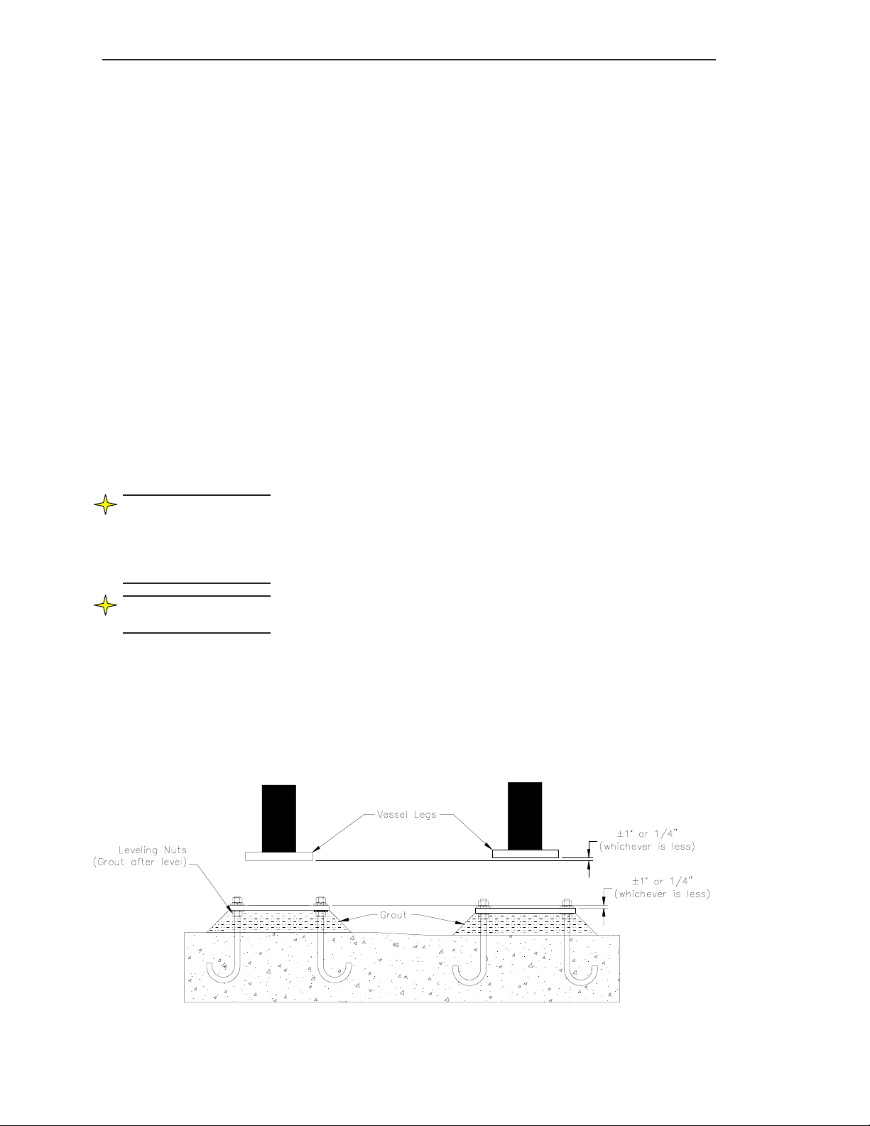
6. Inspect the foundation and vessel mounting surfaces that
will mate to the LD3xi/LD3xiC plates.
a. Check the mounting hole locations and size on both
the foundation base and the vessel foot pad. (Refer
to the TI drawings, Appendix D.)
b. Also check the surfaces for flatness and angular
misalignment. A baseplate with leveling nuts is
recommended. (See Figure 3-1)
7. Mount the LD3xi/LD3xiC assembly to the foundation. (See TI drawings,
Appendix D)
a. Lower the LD3xi/LD3xiC to the foundation. Take
care to align the mounting holes with the foundation
mounting holes/studs.
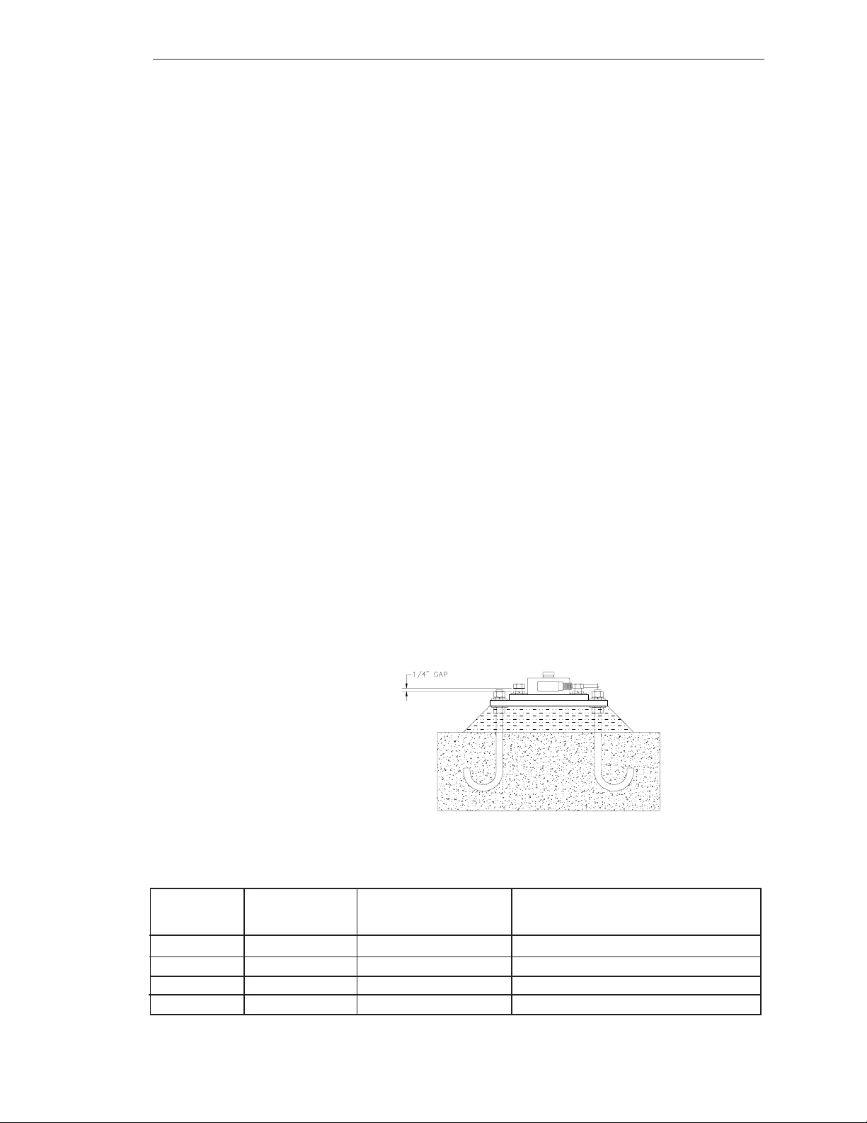
b. Install the bolts and nuts as required. DO NOT fully
tighten the bolts at this time. Leave a 1/4-inch gap
between the nut and the washer to allow for positioning
of the Load Discs. (See Figure 3-2.)
c. Repeat Steps 7a and 7b for the remaining Load Discs.
8. Record the voltage output at “no-load”condition now that it is in
position.
a. Assign a number (1, 2, 3, etc.) to the load disc and make a
note of it.
b. Measure the output of load cell..
c. Repeat steps a and b for all the Load Discs.
Figure 3-2: Leave 1/4-inch gap for positioning
Load Disc # No-Load Output Dead Weight Output Output Change (mV)
(mV) (mV) (Dead Weight Output - No-Load Output)
1
2
3
4
Figure 3-3: Weight Distribution Chart: Record YOUR system’s Load Outputs
3-3
Page 18
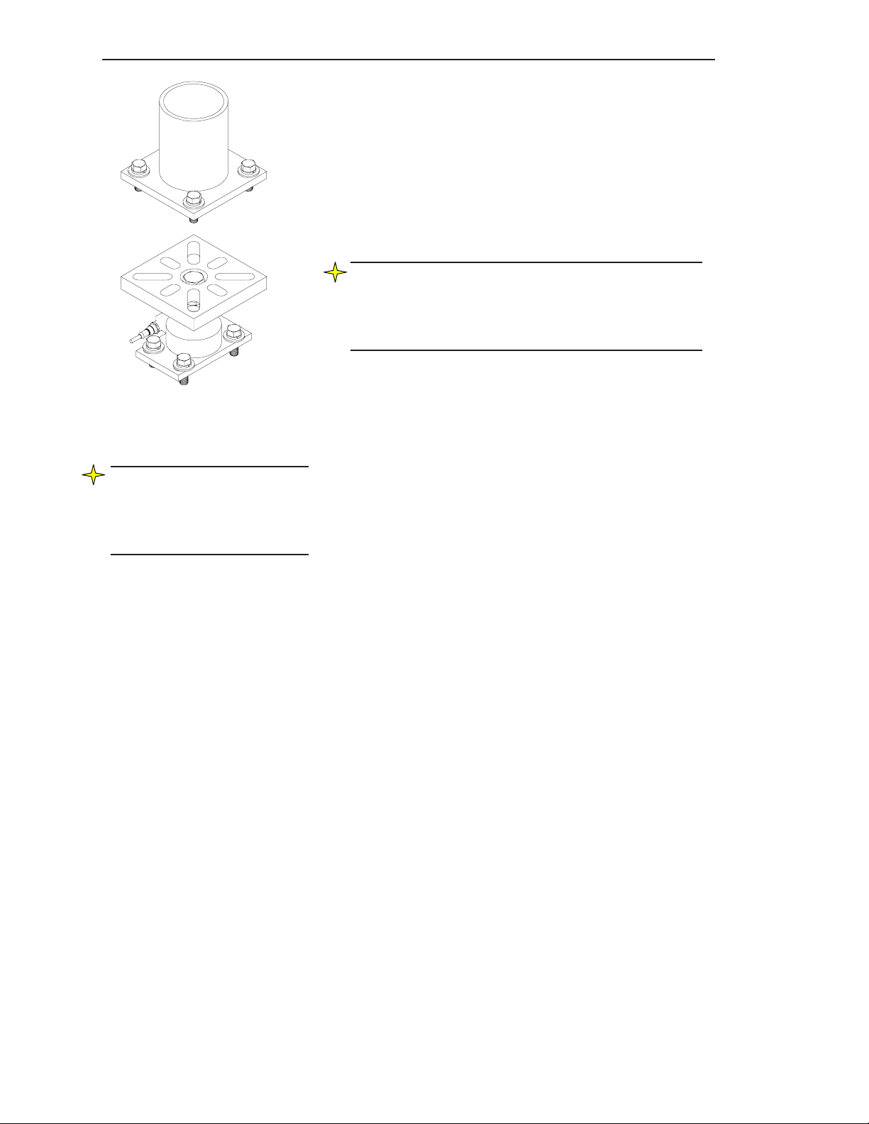
Figure 3-4: Lower vessel onto
top plate.
Note: All output changes should
be positive! If you observe a
negative output change, check
wiring polarity and vessel load
shifting.
Chapter 3. LD3xi/LD3xiC Mounting
9. Mount the vessel to the LD3xi/LD3xiC.
a. Lower the vessel gently onto the Load Discs.
(Alignment pins may be used to help guide and
position the vessel.) (See Figure 3-4)
b. Center the Load Disc top mounting holes with the
vessel mounting holes, using the clearance
available from the bottom mounting holes.
Note: If the vessel hole pattern does NOT match up with
the Load Disc hole pattern, modify the mounting holes on
the vessel. DO NOT hammer or force the Load Disc into
position by tightening the mounting bolts. The vessel holes
will need to be resized or relocated.
c. Place the four top bolts (customer supplied)
through the vessel and the Load Disc mounting
holes. The bolts must be able to pass freely
through the holes without interference.
d. Tighten the bolts, leaving a 1/4-inch gap for
positioning. (See Figure 3-2)
11. Check dead weight output.
a. Record the dead weight output on your Weight
Distribution Chart that was started on page 3-3.
b. Calculate the Output Change. (Change should be
positive.)
3-4
Page 19

Leveling and Shimming
Note: For installations where
leveling nuts are not used, load
balancing on the Load Discs
must be achieved by adding or
removing shims. Adjusting the
Load Discs to distribute the
vessel weight evenly may
require adding shims (supplied
by customer) systematically to
all disc locations.
Note: The Universal Top Plate
will accomodate angular
misalignment up to three
degrees maximum. (Figure 3-5 )
Ideally, the load is distributed
evenly across the top plate.
Chapter 3. LD3xi/LD3xiC Mounting
The main objective of leveling/shimming the vessel is to distribute
the weight evenly on all of the Load Discs. Uneven weight distribution will reduce the accuracy of the weight measurement system as a
whole and in extreme cases may cause Load Disc damage.
Once the general instructions have been completed (page 3-2
through 3-4), begin the leveling and shimming instructions in this
section.
Leveling/Shimming for the Universal Top Adapter Plate
1. Based on the Weight Distribution Chart (Figure 3-3) and
visual inspection, raise the vessel and cut/place shims
as required to adjust the distribution of weight on the
Load Discs. Begin with the “lowest output”
support first! (Objects and support members may cause
the weight to be distributed unevenly. Shimming will
involve some judgement.)
2. Gently lower the vessel and measure the dead weight
output and the output change of all of the Load Discs
to see how they are affected. Record again into the
Weight Distribution Chart on page 3-3.
Note: Shimming the plates of
one Load Disc will probably
affect the weight distribution on
the Load Disc located on the
opposite side. Keep this in mind
while shimming.
Note: Shims are typically
applied between the LD3xi’s
Top Plate and mating vessel
plate, but the gap condition
may exist at either the top or
bottom plates.
CAUTION: If you
need to raise the
vessel or one vessel
leg after installation,
loosen the bolts on all
Load Discs to prevent
overloading.
3. Repeat Steps 1 and 2 until you have achieved the
desired output change of all of the Load Discs.
(Since the output of each load cell may vary, the change
from ‘no load’ to ‘dead weight’ being equal is more
important than the absolute value. )
Figure 3-5: Angular misalignment up to 3 degrees.
3-5
Page 20

Chapter 3. LD3xi/LD3xiC Mounting
Note: Shimming the plates of
one Load Disc will probably
affect the weight distribution
on the Load Disc located on
the opposite side. Keep this in
mind while shimming.
CAUTION: If you
need to raise the
vessel or one vessel
leg after installation,
loosen the bolts on all
Load Discs to prevent
overloading.
Leveling/Shimming for the Leveling Top plate
Adapter, Leveling Base Adapter Plate, and the
Anyadapter Plate
1. Based on the Weight Distribution Chart and visual
inspection, raise the leveling nut to adjust the top plate
until the weight distribution falls within the weight
distribution guidelines (See page 3-4). Check for gaps and
use shims as required.
(Objects and support members may cause the weight to be
distributed unevenly. Shimming will involve some judgement.)
2. Gently lower the vessel and measure the dead weight
output and the output change of all of the Load Discs
to see how they are affected. (See Weight Distribution
Chart page 3-3.)
3. Repeat Steps 1and 2 until you have achieved the
desired output change of all of the Load Discs.
(Since the output of each load cell may vary, the change
from ‘no load’ to ‘dead weight’ being equal is more
important than the absolute value. )
3-6
Page 21

Chapter 3. LD3xi/LD3xiC Mounting
Junction Box Mounting and Wiring
Mounting Junction Box
1. See Figure 3-6. Hold the junction box at the
desired mounting location. Mark the four
mounting holes.
2. Mount the junction box with #8-32 socket head
cap screws and flat washers per your application.
Tighten the screws until snug.
Figure 3-6: Plastic and Stainless
Steel Junction Box Mounting
CAUTION: Only use
Sikaflex™ 1A polyurethane sealant or Dow
Corning™ RTV 739 or
RTV 738. Other
sealants may contain
acetic acid, which is
harmful to sensors and
electronics.
Note: If you have a 61-6036-01
Stainless Steel J-Box with
trimming pots, refer to page
3-10.
Wiring Load Discs to Junction Box
See Figure 3-7. The stainless steel junction box accommodates up
to eight Load Discs, with up to two Load Disc wires at each
terminal. Note that the junction box has no pre-cut holes for conduit
or fittings. Follow this procedure:
1. Install liquid tight fittings.
2. Seal fittings with Sikaflex™ or electrical grade
sealant.
3. Thread the Load Disc cable through the desired conduit
fitting. (See Figure 3-7).
4. Estimate the required length of cable to the terminal strip,
allowing a little extra for strain relief. Cut the excess cable.
5. Strip back 3” (76mm) of the cable sheathing to expose the
four wires and the shield inside. Strip back 1/4” (6mm) of
insulation from the end of each of the wires.
6. Connect the Load Disc wires to the selected TB2-5
terminals on the left side of the junction box: red or
brown wire to +EX, white wire to +SIG, and black
wire to -EX, and blue or yellow wire to -SIG.
Figure 3-7: Wiring Load Discs to Stainless
Steel Junction Box
3-7
Page 22

Chapter 3. LD3xi/LD3xiC Mounting
7. Perform Steps 3 through 6 for each Load Disc you wire to
this junction box.
8. Replace the junction box cover if not ready to begin
wiring the junction boxes together.
Wiring Junction Boxes Together and to Signal Processor
Notes:
1. The procedure below assumes the conduit fitting and
conduit for wiring the junction box to the other junction boxes
and to the signal processor has been installed.
2. Seal all conduit fittings against water entry. Install drain holes at
conduit’s lowest elevation(s) to allow condensation to drain.
3. Use Belden™ 4-conductor shielded interconnect cable or
equivalent to wire junction boxes together and to the signal
processor. For lengths up to 50 feet (15.2 m), use Belden 8723.
4. For 6-wire cable of distances up to 100 feet, use Belden 9773.
5. All spliced wiring routed between junction boxes and signal
processor must be soldered and encapsulated in waterproof
heatshrink.
1. Remove the junction box cover.
2. See Figure 3-8. Route the 4-conductor cable through the fitting
into the junction box farthest from the signal processor. Connect
wires from the cable to the TB1 terminal in the junction box:
red or brown wire to +EX, white wire to +SIG, and black
wire to -EX, and blue or yellow wire to -SIG.
3. Route the cable through conduit to the next junction box.
Estimatethe required length of cable to the terminal strip,
allowing a little extra for strain relief. Cut the excess cable.
Connect wires from the cable to the TB1 terminal in the
junction box: red or brown wire to +EX, white wire to +SIG,
and black wire to -EX, and blue or yellow wire to -SIG.
4. Route another cable through the fitting into this junction box, and
attach wires to the TB1 terminal: red or brown wire to
+EX, white wire to +SIG, and black wire to -EX, and blue or
yellow wire to -SIG.
5. Repeat Steps 3 and 4 until all junction boxes on the
vessel are wired together.
3-8
Page 23

Chapter 3. LD3xi/LD3xiC Mounting
CAUTION: Only use
Sikaflex™ 1A polyurethane sealant or Dow
Corning™ RTV 739 or
RTV 738. Other
sealants may contain
acetic acid, which is
harmful to sensors and
electronics.
6. Route the cable from the last junction box through
conduit to the signal processor. Refer to the signal
processor manual for wiring the junction box to the signal
processor. One vessel takes up one channel in the signal
processor — the channel shows the average value from
all the load discs under the vessel.
Figure 3-8: Wiring Stainless Steel Junction Boxes Together and to Signal Processor
3-9
Page 24

Chapter 3. LD3xi/LD3xiC Mounting
Trim Box Mounting and Wiring
Mounting Trim Box
1. See Figure 3-9. Hold the junction box at the desired
2. Mount the junction box with #8-32 socket head cap
Wiring Load Discs to Trim Box
See Figure 3-10. The summing stainless steel junction box accommodates up to eight Load Discs. Follow this procedure:
1. Thread the Load Disc cable through the desired conduit
mounting location. Mark the four mounting holes.
screws and flat washers. Tighten the
screws until snug.
fitting. (See Figure 3-10).
Figure 3-9: Summing Stainless Steel
Junction Box Mounting
2. Seal fittings with Sikaflex™ or electrical grade
sealant.
3. Estimate the required length of cable to the terminal strip,
allowing a little extra for strain relief. Do not cut the excess
cable.
4. Strip back 3” (76mm) of the cable sheathing to expose the
four wires and the shield inside. Strip back
insulation from the end of each of the wires.
5. The trim box is designed for two, three or four load cells.
Determine the number of load discs that will be wired
to the trim box, and cut the JU jumpers for any unused
inputs. The wire coding for the load disc:
Red or Brown = +EX
Black = -EX
White = +SI
Blue or Yellow = -SI
6. Wire each load disc to the terminals, leaving the cord grips
loose until the trimming has been complete. The terminals
have quick connect levers that open when pushed. A
screwdriver or ballpoint pen can be used to open or close
jaws. The terminals can accommodate wire gauges #14
through #26.
1
/4” (6mm) of
7. Set all the potentiometers fully clockwise for inputs being
used. This will give the maximum output from each
load disc.
3-10
Page 25

Chapter 3. LD3xi/LD3xiC Mounting
8. A calibration of the electronic indicator is needed before before
trimming functions can be done. Refer to the electronic indicator
manual for the calibration procedure.
9. Place test weights above each load cell and record the weight value
displayed on the electronic indicator. The test weights should be
directly above each load cell and not overhanging.
10. The cell that has the lowest weight displayed will not be adjusted; it
will be the reference load cell. Place the weights above a load cell
and adjust the potentiometer to match the displayed weight from the
reference load cell.
11. After each potentiometer adjustment, the zero (no test weights applied)
should be checked.
12. Repeat for each load cell. Do not adjust the reference load cell
potentiometer.
13. When all of the cells are trimmed, a final calibration is required.
Figure 3-10: Wiring Load Discs to Junction Box
3-11
Page 26

Chapter 3. LD3xi/LD3xiC Mounting
3-12
Page 27

Appendix A. Contact Information
Appendix A: Contact Information
Contact Information
You may reach Kistler-Morse corporate headquarters at the
following:
Mail: Kistler-Morse
19021 120th Ave NE Suite 101
Bothell, Washington USA 98011-9513
Telephone: 1-800-426-9010
(425) 486-6600
Fax: (425) 402-1500
E-mail: sales@kistlermorse.com
Website: http://www.kistlermorse.com
European Office
Mail: Kistler-Morse
Rucaplein 531
B-2610 Wilrijk-Belgium
Telephone: 32.3.218.99.99
Fax: 32.3.230.78.76
E-mail: kistler.morse@skynet.be
Technical Service
A complete, unabridged copy of our product warranty is available
upon request from KM. A summary of the warranty, subject to the
terms and conditions listed fully in the warranty, follows:
KM warrants the equipment to be free from defects in material and
workmanship for one year from date of shipment to original user. KM
will replace or repair, at our option, any part found to be defective.
Buyer must return any part claimed defective to KM, transportation
prepaid.
KM maintains a fully trained staff of field service personnel who
are capable of providing you with complete product assistance.
Our field service staff is based in Bothell, Washington USA
(corporate headquarters) and Wilrijk- Belgium (European office).
Phone Consultation
Our Customer Service staff provides the following services by
telephone, via our regular and toll free number (toll free in U.S.A.
and Canada only):
• Technical, application, and troubleshooting assistance
• Spare parts assistance
• Warranty (replacement) assistance
A-1
Page 28

Appendix A. Contact Information
On-Site Consultation
KM’s Field Service staff can provide additional services at your request.
Contact KM at the closest office for rate and scheduling information for
the following services:
• Technical, application, startup, and troubleshooting assistance
on-site
• Training on-site or at our corporate office
• Service calls
• Equipment updates to our latest configuration
Note: Load Disc installation, field
wiring, conduit installation, and
junction box and signal processor
mounting must be performed by the
customer. The AC power must be
connected to the signal processor,
but not energized, prior to KM
beginning work.
General descriptions of some of these standard services follow. Of
course, if your service needs vary from those described, we are
available to discuss them with you.
Installation, Startup Assistance, and On-Site Training
The system will be powered up and checked for proper electrical
operation. For best results, KM requires moving a known amount of
material, such as a truckload, for Live Load calibration. Live Load
calibration will be performed if actual material or weight devices can be
moved. If it is not possible to move material, a Manual calibration will be
performed. Recommendations for the optimal performance of the system
will be provided.
On-site training will include simulation of the Live Load calibration
process (if Live Load calibration can not be performed while KM is on
site) and instruction covering operation and maintenance of the system.
Troubleshooting
KM will troubleshoot systems for mechanical, electrical, calibration, and
wiring errors. Normal component repairs will be made and wiring errors
will be corrected, including replacement of non-repairable printed circuit
boards. (To troubleshoot your own equipment, see Appendix C for
Equipment Troubleshooting charts)
Service Calls
KM will perform on-site repair/replacement services.
Return Material Authorization
If a part needs to be sent to the factory for repair, contact KM’s
corporate office and request a Return Material Authorization (RMA)
number. The RMA number identifies the part and the owner and must be
included with the part when it is shipped to the factory.
A-2
Page 29

Appendix B. System Calibration
Appendix B: System Calibration for the
Load Disc
This chapter describes general procedures
for calibrating the Load Disc system.
Calibration Methods
Before calibrating, install a signal processor. Refer to the signal processor manual for the procedures to input calibration parameters.
There are two calibration methods:
• Live Load calibration — set lo span and hi span while moving
material into or out of the vessel. This is the preferred method.
• Manual calibration — set scale factor counts, scale factor weight,
and zero calibration value without moving material.
For use with Trim Box, refer to Trim Box Mounting and Wiring on page
3-10.
Live Load calibration requires you to move a known quantity of material
into or out of the vessel while performing the procedure. The quantity
of material moved must be at least 25% of the vessel’s total capacity to
provide the best accuracy. Live Load calibration is also based on the
material weight currently in the vessel.
Manual calibration allows you to start using the system as soon as the
load discs, junction boxes, and signal processor are installed and wired,
even if you cannot move any (or enough) material now. Manual
calibration values are based on system parameters, including rated load,
and signal processor A/D converter sensitivity. These values are
known, can be calculated, or can be obtained from the signal processor.
Manual calibration is also based on the material weight currently in the
vessel.
Note that manual calibration does not take into account the actual
response to changes in weight. Theoretically, a change in weight results
in a proportional change in digital counts. However, the structure’s
actual response to weight and interaction with piping, catwalks, roof,
discharge chutes, etc. prevents the system from achieving theoretical
values. Manual calibration is a good start, but to obtain the highest
accuracy, perform a Live Load calibration when scheduling permits you
to move material into or out of the vessel.
Refer to the indicator manual(s) for detailed calibration instructions.
B-1
Page 30

Appendix B. System Calibration
B-2
Page 31

Appendix C. Troubleshooting
Appendix C: Troubleshooting the
Load Disc System
This section describes an output check and some common
problems. For each problem, one or more possible explanations are listed. For each explanation, suggested solutions
are provided.
Functional Check: Measuring Output (while wired to Signal Processor)
Note: The “no-load”
condition is when the
Load Disc stands
alone without any
weight applied.
1. Mesure the output of the load cell using procedure from
2. Verify the output to be between 0mV and +/- 1mV, stable.
3. Repeat Steps 1 and 2 for each LD3xi.
4. If the load cells are installed under the vessel, verify
Functional Check:Measuring Resistance
The following will be true between 0 °F and 100 °F:
1. Measure between the disconnected excitation wires and verify the
resistance to be 700 ohms +/- 15 ohms, with a stable reading.
2. Measure between the disconnected output wires and verify the
resistance to be 700 ohms +/- 15 ohms, with a stable reading.
Note: When using the 61-6036-01 trim
box, and a sensor fails, the sensor must
be replaced. When the sensor wires are
removed from the junction box, the
jumper must be soldered back in place.
page 2-2.
stability of each load cell.
C-1
Page 32

Appendix C. Troubleshooting
Problem Problem Details Solution
Small Amplitude
Changes or Erratic
Fluctuations in display
readings
Fluctuations can be caused
by moisture in cable conduit,
junction boxes, or PCBs.
Fluctuations can be caused
by damaged Load Disc.
Check conduit, junction boxes, and PCBs for
water contamination. Find water entry source
and correct problem. Dry with a hair drier.
Remove/replace corroded parts and materials.
CAUTION
If using sealant to eliminate water entry, use
Sikaflex ™ 1A polyurethane sealant or Dow
Corning™ RTV 739 or RTV 738. Other
sealants may contain acetic acid, which is
harmful to electronics.
Using Digital Multimeter (DMM), check
resistance for individual Load Discs:
1. Measure between the disconnected
excitation wires and verify the resistance to be 700 ohms +/- 15 ohms, with
a stable reading.
2. Measure between the disconnected
output wires and verify the resistance
to be 700 ohms +/- 15 ohms, with a
stable reading.
3. Place one DMM lead on the LD’s shield
wire and take four measurements to each
of the other wires. The reading should
be greater than 5 giga-ohms.
4. Repeat Steps 1 through 3 for each
suspect Load Disc, until damaged Load
Disc is located.
C-2
Page 33

Appendix C. Troubleshooting
Problem Problem Details Solution
Small Amplitude
Changes or Erratic
Fluctuations in
display readings
Sudden Change in
Weight Reading or
System Requires
Frequent
Recalibration
Fluctuations can be caused
by problems with signal
processor.
One broken Load Disc can
cause indicated weight to
shift up or down by large
amount, up to 100% of fullscale live load.
Check signal processor excitation voltage
and incoming AC voltage for accuracy and
stability (refer to signal processor manual).
Using Digital Multimeter (DMM), check
resistance for individual Load Discs:
1. Measure between the disconnected
excitation wires and verify the resistance
to be 700 ohms +/- 15 ohms, with a stable
reading..
2. Measure between the disconnected
output wires and verify the resistance to
be 700 ohms +/- 15 ohms, with a stable
reading..
3. Place one DMM lead on the LD’s shield
wire and take four measurements to each
of the other wires. The reading should be
greater than 5 giga-ohms.
4. Repeat Steps 1 through 3 for each
suspect Load Disc, until damaged Load
Disc is located.
Sudden change in weight
reading can be caused by
problems with signal processor.
Check signal processor excitation voltage
and incoming AC voltage for accuracy and
stability (refer to signal processor manual).
C-3
Page 34

Appendix C. Troubleshooting
C-4
Page 35

Appendix D. Technical Drawings
Appendix D. Technical Drawings (TI)
This appendix contains the following technical drawings for the LD3xi:
Drawing No. Drawing Title
TI-LC.LD3xi-01 Installation Arrangements, 220-5500 lb, Load Disc 3xi (13 Pages) Page
Installation Instructions 1-4
LD3xi with Leveling Top Universal Adapter Plate 5
LD3xi with Universal Top Adapter Plate 6
LD3xi with Anyadapter Plate 7
Mounting hole patterns for Anyadapter 8
LD3xi with Leveling Base Adapter Plate 9
LD3xi Mounting dimensions 10
LD3xi mounting to floor and I-beam 11
LD3xi cabling using molded junction conn, J-Box 12
LD3xi conduit/non-conduit cable layout 13
TI-LD3xi-01 LD3xi Typical Cabling Diagram (1 page) 1
TI-LC.LD3xiC-01 Installation Arrangments, 220 - 22,000 lbs Load Disc 3xiC (7 pages)
LD3xiC Installation Instructions 1-3
LD3xiC Mounting Dimensions 4
LD3xiC Mounting to Floor and I-beam 5
LD3xiC Conduit/Non-conduit Cable Layout 6
LD3xiC Orientation 7
D-1
Page 36

Appendix D. Technical Drawings
D-2
Page 37

Page 38

Page 39

Page 40

Page 41

Page 42

Page 43

Page 44

Page 45

Page 46

Page 47

Page 48

Page 49

Page 50

Page 51

Page 52

Page 53

Page 54

Page 55

Page 56

Page 57

 Loading...