


PWDB-GW User Manual
Kisan Telecom

2 / 40
Content
1. Introduction....................................................................................................................................................................5
1.1. General Introduction.....................................................................................................................................5
2. Network configuration of system.......................................................................................................................5
2.1. Network configuration.................................................................................................................................5
3. System Specifications ................................................................................................................................................6
3.1. General Specifications ..................................................................................................................................6
3.2. System specifications....................................................................................................................................7
3.2.1. System Specifications......................................................................................................................7
4. Mechanical Specifications .......................................................................................................................................8
4.1. PWDB-GWMHU ...............................................................................................................................................8
4.1.1. Mechanical Design............................................................................................................................8
4.1.2. Dimension .......................................................................................................................................... 10
4.1.3. Mechanical specification ............................................................................................................ 11
4.1.4. Descriptions of PWDB-GW MHU...........................................................................................11
4.1.5. Port Configuration......................................................................................................................... 12
4.1.6. Module Composition.................................................................................................................... 14
4.1.7. Function of modules.....................................................................................................................15
4.1.8. PSU ........................................................................................................................................................16
4.2. PW
DB-GW RU...............................................................................................................................................18
4.2.1. Mechanical Design.........................................................................................................................18
4.2.2. Dimension .......................................................................................................................................... 19
RU System picture and Size 510(H) X 300(W) X 316.5(D) mm................................. 19
4.2.3. Mechanical Specification ............................................................................................................ 19
4.2.4. Description of PWDB-GWRU.................................................................................................... 20
4.2.5. Port Configuration......................................................................................................................... 21
4.2.6. Module Composition.................................................................................................................... 22
4.2.7. Function of Modules ....................................................................................................................23
5. Block Diagram............................................................................................................................................................26
6. Administration Program (RptMan1900) ....................................................................................................... 27
6.1. System Requirement..................................................................................................................................27
6.2. Cable connection .........................................................................................................................................27
6.3. Screen ................................................................................................................................................................28
6.4. Status Display ................................................................................................................................................ 28

3 / 40
6.4. Status Display ................................................................................................................................................ 28
6.5. Control Policy.................................................................................................................................................29
6.6. Menu ..................................................................................................................................................................29
6.7. Toolbar...............................................................................................................................................................30
6.8. Progrm operation ........................................................................................................................................ 31
6.8.1. Initiating communication...........................................................................................................31
6.8.2. Disconnection...................................................................................................................................31
6.8.3. PWDB-GWMHU Status Retrieval and Control.................................................................32
6.8.4. PWDB-GWRU Status Retrieval and Control......................................................................34
6.8.5. Firmware download ......................................................................................................................37
6.9. Additional features .....................................................................................................................................38
6.9.1. ASD (Auto Shutdown) Function .............................................................................................38
6.9.2. ALC (Auto Level Control) Function........................................................................................39
Appendix A Factory setting value for each equipment .................................................................................40

4 / 40
IMPORTANT NOTE:
FCC RF Radiation Exposure Statement:
This equipment complies with FCC RF radiation exposure limits set forth for an
uncontrolled environment. This equipment should be installed and operated with a
minimum distance of 20 centimeters between the radiator and your body.This
transmitter must not be co-located or operating in conjunction with any other antenna
or transmitter.
5 / 40
1. Introduction
1.1. General Introduction
As an equipment to clear the shadows inevitably generated among the adjacent cells of
WCDMA and GSM, PWDB-GW simultaneously supports both WCDMA and GSM and
effectively repeats the signals between terminals in dead area and BTS
The main objectives of PWDB-GW are as follows:
- The expansion of service coverage
- The enhancement of service quality at the specific areas such as in tunnel or in-
building
- The enhancement of signal strength at the places where the signal is weak
2. Network configuration of system
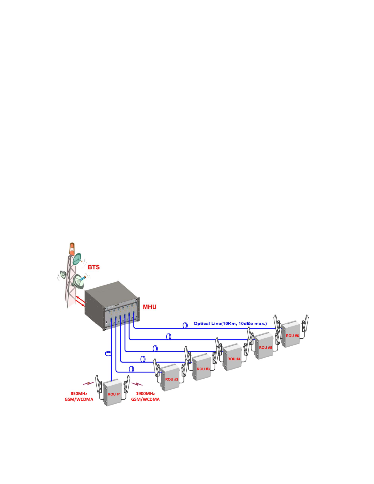
2.1. Network configuration
PWDB-GW repeater is an equipment to clear the shadows and fill the gaps existing
among the adjacent cells and enhances the quality of services by extending coverage of
WCDMA and GSM.
The above architecture is for the case when the MHU is co-located with BTS (GSM or

6 / 40
WCDMA), and the service is provided remotely.
System configuration
MHU Capacity: 1 Optical Branch/DOU and 6 DOU/MHU (6 Optical Branch/MHU)
System Connection: Optic cable between MHU and RU
Optic Wavelength: 1310nm for FWD, 1550nm for RVS
Max loss of optic cable (between MHU and RU): 2 ~ 10dBo
3. System Specifications
3.1. General Specifications
Item PWDB-GW MHU PWDB-GW RU
Enclosure Type
7U-Shelf type
19” standard rack mountable
In-door use
Cabinet
W H D 19"(482.4) X 310(7U) X 450mm 510(H) X 300(W) X 316.5(D)mm Dimension
(mm)
Weight
15.5Kg 33Kg
Power Supply 110-120Vac (Tolerance ±10%), 60Hz 110Vac, 60Hz
Power Connector ID-NO3BEH MS3106A16-10S
RF In/Out Port SMA Female, rear side N Type Female, bottom side
Optic Connector Type FC/APC, front side FC/APC, bottom side
Optic Wavelength FWD: 1310nm / RVS: 1550nm
Operating Temperature -5℃ ~ 40℃ -5℃ ~ 50℃
Environmental requirement
The repeater RU shall be operated in the temperature range of
-5℃ ~ 50℃

7 / 40
3.2. System specifications
3.2.1. System Specifications
Item Specification Remarks
DL Frequency Range
Contiguous 25MHz Bandwidth in 1930 ~ 1990MHz
Contiguous 25MHz Bandwidth of 869 ~ 894MHz
Uplnik Optical Communication
Frequency Stability 0.02PPM
Mode GSM and WCDMA
System Delay DL: 8usec max. UL: 5usec max.
Tx-Rx Isolation 100dB min. @Between RU Tx ANT and MHU Rx Output
Impedance 50 Ohm
Pass-Band Ripple 3dB max. 25MHz BW
FWD Input Power -10 ~ 0dBm/total, -5dBm/total is recommended
FWD Output Power
40dBm /total for 1900MHz RU ANT Port
40dBm /total for 850MHz RU ANT Port
RVS Input Power -60dBm/total max. at RU each ANT Port
RVS Output Power -20dBm/total max. at MHU each Rx Output Port
System Gain FWD: 50dB max. RVS: 40dB max.
FWD Spurious Comply to 3GPP2, FCC regulation
RVS Noise Figure 5dB max. @ 40dB Gain Max. Gain
Gain Control Range FWD: 20dB by 1dB Step RVS: 20dB by 1dB Step RU OLC Gain
VSWR 1.5 : 1 max. @ All input/output ports
Optical Wavelength FWD: 1310nm RVS: 1550nm
RF I/O Connector DU: SMA Female RU: N-type Female
8 / 40
4. Mechanical Specifications
4.1. PWDB-GWMHU
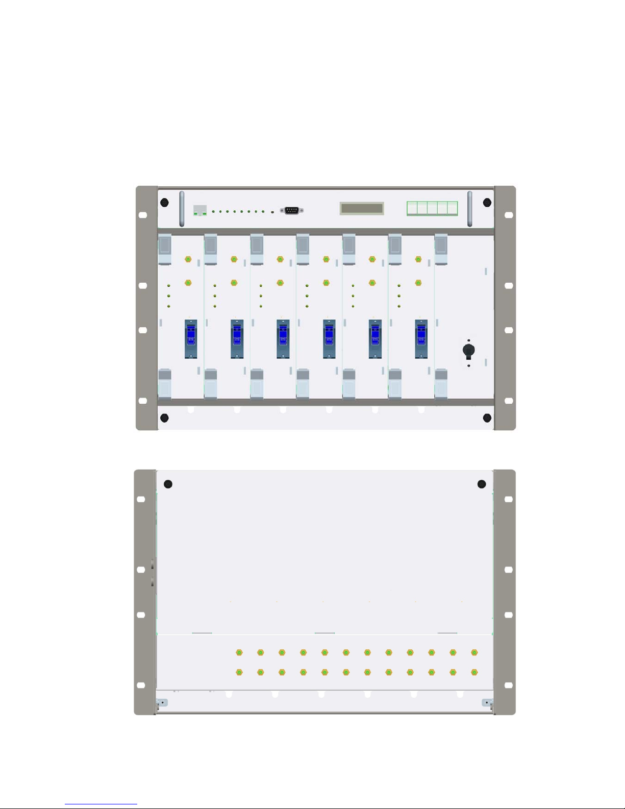
4.1.1. Mechanical Design
[FRONT]
[REAR]

9 / 40
[MHU Figure]
10 / 40
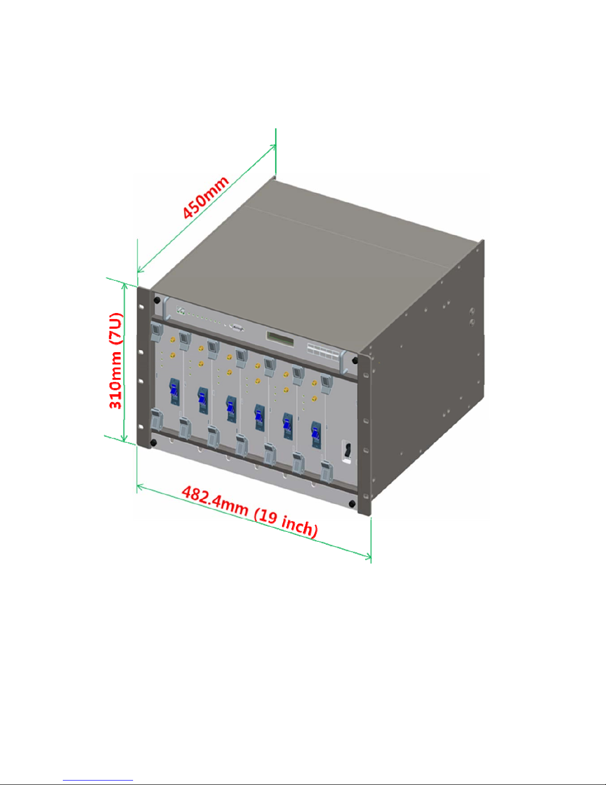
4.1.2. Dimension

11 / 40
4.1.3. Mechanical specification
No Items Specifications
1 Exterior view
1. Shelf attachable type to both INDOOR and OPEN RACK
2. W 19"(482.4) X H 310(7U) X D 450mm
3. Weight: 15.5 Kg (1DOU included)
2 Material
Aluminum (AL5052, AL6063) is mainly used for protection
from corrosion by external environments.
3 Connector Type
1. Optic I/O: FC/APC at front side
2. RF I/O: SMA Female at rear side
3. Monitor port: SMA Female at front side
4 Power Input
1.Power: 110-120Vac, 60Hz
2.Connector: IN-NO3BEH
5 Ground
14SQ 2Hole ground pipe (right side of shelf) and M4 “O” rug
ground (rear side of shelf)
6 Communication Port 9P D-SUB (GUI), front side
4.1.4. Descriptions of PWDB-GW MHU
[Forward Path]
The signal from GSM or WCDMA BTS is fed to the RF input port of MHU rear side.
Initially, in the MHU RVS/FWD COMbiner(MRFCOM) module, the input signal power
level is measured and combined with the modem signal(360MHz), and it becomes the
input signal to the optic module to be transmitted to RU.
[Reverse Path]
The WCDMA or GSM RVS signal input from RU through the optic module is divided
into RF and modem signal, and RF RVS signal level is measured by the MRFCOM
module, which becomes the input signal to the BTS of GSM or WCDMA.
12 / 40
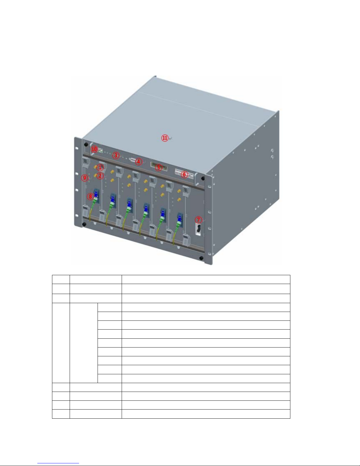
4.1.5. Port Configuration
No Items Description
1 TX_MON Monitor port for MHU FWD input signal from BTS (-20dB)
2 RX_MON Monitor port for MHU RVS output signal to BTS (-20dB)
RUN Green Blinking: CPU run, OFF(Gray): CPU stop
ALM Summary Alarm of MHU, Green: Normal, Red: Alarm
RU1 The status of communication with RU1, Green: Normal, Red: Alarm
RU2 The status of communication with RU2, Green: Normal, Red: Alarm
RU3 The status of communication with RU3, Green: Normal, Red: Alarm
RU4 The status of communication with RU4, Green: Normal, Red: Alarm
RU5 The status of communication with RU5, Green: Normal, Red: Alarm
RU6 The status of communication with RU6, Green: Normal, Red: Alarm
3 LED1
RESET NMS board HW Reset
4 DEBUG PC connection port for GUI S/W (9pin D-SUB)
5 DISPLAY Key pad input display
6 DATA INPUT Equipment status/check, control data input
7 Power Switch AC110V power ON/OFF switch

13 / 40
8 Optic Connector FC/APC, optic connector
PWR DC power supply status of the DOU Card
LD LD Alarm, Green: Normal, Red: Alarm
9 LED2
PD PD Alarm, Green: Normal, Red: Alarm
10 RJ45(Master) Connection port to the master for the NOC
11 NMS board Sliding type
12 AC INPUT External AC power input port (rear part)
13 Tx IN MHU FWD RF connection port from BTS (rear part)
14 Rx OUT MHU RVS RF connection port to BTS (rear part)

14 / 40
4.1.6. Module Composition
No Module Voltage Used Remarks
①
MHU NMS Controller 9Vdc
②
MHU PSU(Power Supply Unit) 9Vdc/6.5Vdc
③
MRFCOM(MHU RVS FWD Combiner) 6.5Vdc
④
MHU FSK Modem 9Vdc
⑤
MHU Optical Transceiver Unit (DOU) 6.5Vdc
[NMS UNIT]
[PSU] [DOU]
⑤
①
②
③
④

15 / 40
4.1.7. Function of modules
No Module Functions
1
[MHU NMS Controller]
Monitors/controls the status and configurable
items of each module in MHU
2
[PSU]
Converts AC110V into DC9V and DC6.5V, and
provide them to each module in MHU
3
[MRFCOM]
Detect the FWD/RVS RF signal power level of
input/output ports of the MHU. Also provide the
connection pin to NMS controller and FSK
modem. This module combines/divides the RF
signal and FSK modem signal, and this module
has -20dB monitor port for Tx input/Rx output.
4
[FSK Modem]
Data modem for MHU and RU communication
MHU → RU frequency: 360MHz
RU → MHU frequency: 340MHz
5
[DOU]
Converts E/O(or O/E) the FWD and RVS signals.
Wavelength: Tx 1310[nm], Rx 1550[nm]

16 / 40
4.1.8. PSU
PSU converts external AC110V into DC and supplies +9V, +6.5V to each module in
MHU.
The drawing of PSU is as follows.
SWITCH
F.G
AC_N
AC_L
INPUT
+9V
+6.5V
ALM
+6.5V
+9V
OUTPUT
PWR ON
GND
GND
GND
GND
GND
YW396-05V(연호전자)
[PSU Capacity]
Output
Vol t a ge
Maximum
current
Watt
+9V 3 A
+6.5V 5 A
59.5 W
[PSU Pin Map]
SWITCH PIN Type: YW396-02V
Pin no. 1 2
Spec. Switch_IN Switch_Out
INPUT PIN Type: YW396-05V
Pin no. 1 2 3 4 5
Spec. AC_L N.C AC_N N.C F.G

17 / 40
OUTPUT PIN type: 5566-10 (MOLEX)
Pin no. 1 2 3 4 5
Spec. ALARM +6.5V +6.5V +9V +9V
Pin no. 6 7 8 9 10
Spec. GND GND GND GND GND
Circuit Diagram of Power Diagram

18 / 40
4.2. PWDB-GW RU
4.2.1. Mechanical Design

19 / 40
4.2.2. Dimension
RU System picture and Size 510(H) X 300(W) X 316.5(D) mm
4.2.3. Mechanical Specification
No Item Description
1 Dimension & Weight
1. Dimension: 510(H) X 300(W) X 316.5(D) mm
(plinth included)
2. Weight: 33Kg
2 Method of Cooling Natural convection (Heat-sink)
3 Door Locking Type Two locks on the left side of the front of cabinet
4 Optic Connector
1. Position: Cabinet inside
2. Connector type: FC/APC
* Optic cable tray is provided inside of cabinet.
5 ANT PORT
1. located at the bottom side of cabinet
2. Connector Type: N Type Female
6 Power Input
1. Power: 110VAC/60Hz
2. Position: bottom side of cabinet
3. Connector: MS3106A 16-10S
7 Ground 2Hole 16SQ at the left and right side of cabinet
8 Waterproof condition IP65 compliant
9 Misc. Features
1. Easy to maintain
2. Pole mountable (i.e., telegraph pole)
3. Lamp embedded with automatic On/Off function
according to the door opening status
4. Torque hinge used

20 / 40
4.2.4. Description of PWDB-GWRU
[Forward path]
The RF and modem signal sent from optic module of MHU is first divided into RF and
modem signal at Divider in RU, then the CDMA RF signal is amplified and filtered at
the RFBS module and the modem signal is conveyed to CPU of NMS controller through
FSK modem.
The CDMA RF signal input from the RFBS module is linearly amplified up to high
power level on HPA, passed through the Front-End Filter Unit, and finally transmitted
through an antenna.
[Reverse Path]
CDMA Rx signals incoming from an antenna are first passed by the Front-End Filter
Unit, amplified on a low noise and high gain performance and filtered on RRLNA/RRBS,
and combined with modem signal at combiner(RRCOM). The combined signal is
transmitted to MHU through the optic module.

21 / 40
4.2.5. Port Configuration
No Item Description
1 AC INLET AC 110V Power Cable Connection
2 1900MHz ANT Port 1900MHz Band ANT RF Cable Port
3 850MHz ANT Port 850MHz Band ANT RF Cable Port
4 1900MHz Monitor Port
Monitor port coupled by -40dB compared to the output
power of the 1900MHz ANT Port
5 850MHz Monitor Port
Monitor port coupled by -40dB compared to the output
power of the 850MHz ANT Port
6 Optical Cable INLET Optic cable connection hole
1900MHz ANT Port
1900MHz Monitor Port
1900MHz ANT Port
1900MHz Monitor Port
AC100V INLET
Optical Cable INLET

22 / 40
4.2.6. Module Composition
Module operational voltage table
No Module Voltage Used Remarks
1 Divider
2 RF FWD Band Selector for 1900MHz (RFBS) 6.5Vdc
3 RF FWD Channel Selector for 850MHz (RFCHS) 6.5Vdc
4 Slave Optical Transceiver Unit (SOU) 6.5Vdc
5 RF Modem (FSK Modem) 9Vdc
6 RU RVS COM for Signal combing (RRCOM)
7 RU RVS Band Selector for 1900MHz (RRBS) 6.5Vdc
8 RU RVS Band Selector for 850MHz (RRCHS) 6.5Vdc
9 HPA for 1900MHz 29Vdc
10 HPA for 850MHz 29Vdc
11 FE-Duplexer(Front-End Filter Unit) for 1900MHz
12 FE-Duplexer(Front-End Filter Unit) for 850MHz
10 PSU 110Vac
11 NMS Controller 9Vdc
12 Back Board Ass’y 6.5Vdc / 9Vdc
RFBS
RFCHS
RRBS
SOU + FSK Modem + RRCOM
NMS Controller
1900MHz FE-Duplexer
1900MHz HPA
Divider
RRCHS
850MHz HPA
850MHz FE-Duplexer
PSU

23 / 40
4.2.7. Function of Modules
No Module Description
1
[Divider]
Divides RF signal to CDMA signal and modem
signal, and sent to RFBS and FSK modem.
2
[RFBS]
Controls the gain of 1900MHz FWD path, filtered
FWD band, control the crust factor of RF signal,
and perform the ALC function. The module
output is sent to 1900MHz HPA.
3
[RFCHS]
Controls the gain of 850MHz FWD path, filtered
FWD band, control the crust factor of RF signal,
and perform the ALC function. The module
output is sent to 850MHz HPA.
3
[SOU]
Converts E/O (or O/E) of FWD and RVS signals.
Wavelength: TX 1550[nm], RX 1310[nm]
4
[FSK Modem]
Data modem for RU and MHU communication
RU → MHU frequency: 340MHz
MHU → RU frequency: 360MHz
5
[RRCOM]
Combines RVS 850MHz signal, 1900MHz signal
and Modem signal, and provides the combined
signal to optical module in order to convert E/O.
6
[RRBS]
Amplifies RVS 1900MHz signal by low noise high
gain, filtering the desirable band and control the
RVS path gain of RU.
6
[RRCHS]
Amplifies RVS 850MHz signal by low noise high
gain, filtering the desirable band and control the
RVS path gain of RU.

24 / 40
8
[1900MHz HPA]
16Watt(42dBm) High power amplifier that
amplifies the RU 1900MHz signal by linearizer
and send to RU ANT through the 1900MHz FE-
Duplexer.
8
[850MHz HPA]
16Watt(42dBm) High power amplifier that
amplifies the RU 850MHz signal by linearizer and
send to RU ANT through the 850MHz FE-
Duplexer.
[1900MHz FE-Duplexer]
Front end duplexer that passes through 1900MHz
desired FWD and RVS frequency bands.
9
[850MHz FE-Duplexer]
Front end duplexer that passes through 850MHz
desired FWD and RVS frequency bands.
10
[PSU]
Converts AC 110V to DC 29V / 9V / 6.5V / 5.5V,
and distributes the voltages to each modules. It
has RU AC power on/off switch.
11
[NMS Controller]
Monitors the status of RU each module, and
controls the configurable items of the RU
modules.
12
[Interface BD]
Provides operating voltage and monitor/control
signal to modules which are connected to
interface B’D, and supports a connection port to
communicate with NMS B’D.

25 / 40
Circuit Diagram of Power

26 / 40
5. Block Diagram

27 / 40
6. Administration Program (RptMan1900)
Administration program (RptMan1900) is a management program for PWDB-GWand
provides status monitoring and control functions to users.
6.1. System Requirement
System: Desktop or laptop PC
OS: Windows XP or later version
Resolution: 1024 768 or more
Connection Cable: 9 pin serial cable (cross type)
6.2. Cable connection
The cable connection between repeater and PC (GUI program) is illustrated below.
The NMS port of repeater MHU provides two (2) ports; one is D-sub port for GUI and
another is Ethernet port for NOC(Network Operating Center).
Repeater
NMS
port
D-Sub 9Pin
Female
2
3
5
D-Sub 9Pin Male
2
3
5
D-Sub 9Pin Female
PC GUI
Program
2
3
5
Ethernet port for NOC
D-sub port for NOC

28 / 40
6.3. Screen
Section Description
Window Title
Displays the name of management program (GUI), i.e. RptMan-
PW1900.
Displays the type of equipment which is currently connected to
program (MHU or RU).
Menu Bar
Presents working menu for operators.
It is associated with tool icons, which can activate the tool bar menus.
Toolbar
Presents icons (button type) for frequently used command.
User friendly icons are used.
Icons are activated or disabled as to the status of repeater.
Work Space
Status information and control function are provided with a block
diagram view of MHU and RU.
Provides the working space of windows or dialogs.
6.4. Status Display
Status of repeater is displayed by LED and values. The meanings are as follows.
LED
Alarm:
/ blinking means ALARM, means NORMAL
On/Off:
ON, OFF
Exception) for HPA,
is ON, is OFF
Work Space
Title
Menu Bar
Toolbar
Node Tree

29 / 40
Value
Units are not displayed (omitted).
Value displayed in box (
)
Control
The shape of mouse cursor is changed to
on controllable item.
The texts of controllable LED or values are displayed in BOLD font.
6.5. Control Policy
System parameter is controlled one at a time.
Click a control item (button) to popup a control popup dialog.
Once a dialog popup window is opened, it stays there for repeated control.
6.6. Menu
Menu Sub Menu Function
Connect Connects GUI and repeater to communicate
Disconnect Disconnects GUI and repeater
File
Exit Finishes admin program.
Power Table Presents a dialog to manipulate RF power table
TC Table Presents a dialog to manipulate temperature compensation
table
Image Compression Compressed the firmware file (executable file of repeater)
to download
Image Downloader Downloads compressed firmware file to repeater
Factory Setting Sets configured values of repeater back to values of factory
settings
Action
Gain Setting Tx: set ATT to have 35dBm remote ANT output.
Showing range and the
result of control
Configurable Item
Targ e t E q ui p me nt .
(MHU or RU)

30 / 40
Rx: set ATT to have 40dB of Rx total gain from RU to MHU
including optical loss.
MHU Window Presents MHU status window in work space
View
Remote Window Presents RU status window in work space
Cascade
Tile Horizon
Cascade or tile horizon arrangement of repeater status
windows in work space
Window
Packet Debug
Presents debug window in work space displaying packets
between repeater and GUI program
Help
About RptMan1900 Displays version of GUI program named RptMan (Repeater
Manager)
6.7. Toolbar
ITEM ICON Function
Communication
Establishment
Establishes RS-232C connection to the repeater, then
GUI starts to communicate and status of repeater are
polled and displayed.
Communication
Disconnection
Disconnects communication with connected repeater.
Status of repeater is not updated.
Polling
Stop/Resume
Stops or resumes polling action of GUI program.
(activated in toggling way)
Power Table
Presents a dialog to manipulate RF power table
T/C table
Presents a dialog to manipulate temperature
compensation table
Debug Packet
Displays packet data between GUI and repeater like
protocol analyzer and it may help debugging of
software
Compression of
image file
Compresses image file of repeater
Gain Setting
TX: set ATT to have 35dBm of output at the RU ANT
Port
RX: set ATT to have 40dB gain of Rx path
Tx/Rx Gain setting function carry out Tx/Rx gain
including optical loss compensation automatically.
MHU Download
Download MHU firmware files to a designated
equipment.
Remote Download
Download RU firmware files.
MHU Factory Setting
Initialize MHU parameters to factory setting. values
RU Factory Setting
Initialize RU parameters to factory setting values.
Help
Shows version information

31 / 40
6.8. Progrm operation
6.8.1. Initiating communication
Function Establishment of communication between GUI and repeater
Method
Click
button in toolbar of GUI program
Port Combo box to choice com port (COM1, COM2, …)
OK Button Initiates communication between GUI and repeater, then
close this popup window(“Open Connection”)
When communication port is establish correctly, you can
see the communication status by the icon blinking of
(right-bottom side
of the main screen)
Description
Cancel Button Cancels communication establishment and close the
popup window
6.8.2. Disconnection
Function Disconnection of GUI and repeater
Method
Click
button in toolbar of GUI program
Description GUI on PC and repeater disconnect communication each other by this
action.

32 / 40
6.8.3. PWDB-GWMHU Status Retrieval and Control
(1) MHU Tree: This window display the tree configuration of RUs connected with MHU
① MHU Press MHU to open the MHU screen
(1) MHU Tree
② RU1900-1 ~ 6 Press RU1900-# to open each RU screen
(2) MHU Screen window
① General & Environment
This part is included common parameter of
MHU like system information of environment
(3) MHU
Screen
② DOU Status/Control
This screen provides information of 6DOUs
LD Power & Lower limit value
PD Power & Lower limit value
Tx Input, Rx Output Power & Limit value
RU Install information
Group Description
Version: Version of firmware
Type: Repeater unit type
ID: ID of MHU for the communication
(2) MHU Screen Window
① General & Environment part
② DOU Status & Control
p
art
(1) MHU Tree
① MHU
② RU1900-1 ~ 6

33 / 40
User Connect: Connection status of COM port of
repeater
PSU: Status of PSU
TMPCUR: Current temperature of the equipment
TMPUPR: set the upper threshold value of
temperature (button) and alarm status (LED)
LD Power: Transmitted optical power level to RU
LD Lower: Lower limit level of the LD power
PD Power: Received optical power level from RU
PD Lower: Lower limit level of the PD power
1900 Tx Input: Tx level input from 1900MHz BTS
1900 Tx Upper: Upper limit of Tx input level
1900 Tx Lower: Lower limit of Tx input level
1900 Rx output: Rx level output to 1900MHz BTS
1900 Rx Upper: Upper limit of Rx output level
850 Tx Input: Tx level input from 850MHz BTS
850 Tx Upper: Upper limit of Tx input level
850 Tx Lower: Lower limit of Tx input level
850 Rx output: Rx level output to 850MHz BTS
850 Rx Upper: Upper limit of Rx output level
RU install: display the RU installation status

34 / 40
6.8.4. PWDB-GWRU Status Retrieval and Control
Group Description
Version: Version of firmware
Type: Type of repeater
Name: Name of repeater RU
User Connect: Connection status of COM port of repeater
PSU: Status of PSU
TMPCUR: Current temperature of repeater RU
TMPUPR: Value/control of upper threshold of temperature
(button) and alarm status (LED)

35 / 40
LDPWR: Value of LD power (box) and status of LD (LED)
LDLWR: Value/control of lower threshold of LD power
(button) and lower alarm status of LD power (LED)
PDPWR: Value of PD power (box) and status of PD (LED)
PDLWR: Value/control of lower threshold of PD power
(button) and lower alarm status (LED)
Center Freq: Set the FWD Center frequency value, and
shows PLL alarm status
ATT: Set ATT to control FWD gain, and shows it’s value.
Displayed ATT value = USR ATT + ALC ATT
USR ATT: When ATT is set, USR ATT is set to ALC ATT +
(ATT change).
ALC ATT: It is automatically adjusted by HPA ALC to control
FWD gain, and it is set to “0” when ATT is controlled.
CFR On: Crest factor reduction function On/Off
OUT On: Output signal On/Off control function of RFBS
Version: S/W and Image version of CFR Board in RFBS
INPWR: FWD RF input power at ADC point of RFBS
Num FA: Currently operating the number of FA
On/Off: Status/control the operation state of HPA
OVTMP: Alarm status of HPA Over-temperature
OVPWR: Alarm status of HPA Over-Power
VSWR: Alarm status of HPA VSWR
OUT PWR: Output power level of HPA(box)
OUT UPR: Display/control of upper threshold of HPA output
power(button), alarm status(LED)
OUT LWR: Value/control of lower threshold of HPA output
power(button), alarm status(LED)
ALC: Set ALC level for HPA output, and shows ALC status.
ASD(Auto Shutdown): ASD level(button), and running status
of function(LED).

36 / 40
ASD On/Off: When input upper threshold alarm is occurs,
set ASD activation, and shows its status.
Pilot On/Off: Set CW signal generation, and shows its
status. It is used for RVS gain setting.
IN PWR: RVS input power value of RRBS
IN UPR: Set RVS input upper threshold, and shows the
alarm status of input upper threshold RVS.
OUTPWR: RVS RF output power of RRBS
ATT: Set ATT to control RVS gain, and shows it’s value.
Center Freq: Set the RVS Center frequency value, and shows
PLL alarm status

37 / 40
6.8.5. Firmware download
Download of firmware is normally required when functional upgrade is needed or
when bug or erroneous actions of firmware are fixed.
Downloading improper images (executable file of repeater CPU) may cause seriously
harmful damages to equipment.
Download takes the following steps.
① Convert firmware source file (*.bin) to a downloadable file format.
Main menu: Action → Image Compression, toolbar:
② Open a pop-up window showing the status of the target equipment for firmware
download.
Method 1) Main menu View ¡æ Select Donor Windows or Remote Windows
Method 2) In Block View Dialog window, select Donor Windows or Remote Windows
③ Download firmware to the target equipment.
Method 1) Main menu Action ¡æ select Image Download menu
Method 2) In toolbar, select
for MHU, and select for RU
After that, download firmware after selecting the firmware file for the target
equipment.
File conversion procedure
Select target file
Perform function
Store modified
Select target file

38 / 40
Download procedure
6.9. Additional features
6.9.1. ASD (Auto Shutdown) Function
1. If the power level is above the shut down level for longer than 1 second, turn off
HPA.
2. During shut down state, monitor RFCHS output power. If the level is below 5dB from
shut down level, turn on HPA automatically.
3. Monitor HPA output power in normal operation, and monitor RFCHS output power
during shut down.
Display selected file information
Display progress of firmware download
Select file
Perform operation
Longer than 1 sec, HPA off

39 / 40
6.9.2. ALC (Auto Level Control) Function
1. If the power level reaches the ALC level, prevent to increase more than ALC level by
using ATT control.
2. By memorizing the existing ATT value, the ATT value before ALC can be reused even
when the power is reduced.
No ATT change
ATT increase(Gain decrease)

40 / 40
Appendix A Factory setting value for each equipment
MHU RU
Item Value Item Value
MHU TEMP UPR 80 RU TEMP UPR 80
1900/850MHz Tx IN UPR -10 RFBS ATT 30
1900/850MHz Tx IN LWR -20 Hidden ATT 1900/850MHz Rx OUT UPR -10 PLL Optic LD LWR 0 RFAGC ATT 30
Optic PD LWR -10 HPA On/off Off
HPA OUT UPR 42
HPA OUT LWR 20
ALC Level 40
ALC On/Off ON
ASD Level 43
ASD On/Off ON
RRBS ASD ON
RRBS IN UPR -10
RRBS ATT 30
RRBS PLL Optic LD LWR 0
Optic PD LWR -10
 Loading...