


LMR250R01 Operating Manual
(FCC ID: T7MLMR250R01C1)
2012. .
Kisan Telecom

2 / 30
Kisan Telecom Confidential Proprietary
Content
IMPORTANT NOTE:..............................................................................................................................................................4
FCC RF Radiation Exposure Statement:...................................................................................................................4
1. Intro
duction....................................................................................................................................................................5
1.1
. General Introduction.....................................................................................................................................5
2. S
ystem Network Configuration............................................................................................................................5
2.1
. Network configuration.................................................................................................................................5
3. Sy
stem Specifications ................................................................................................................................................6
3.1
. General Specifications..................................................................................................................................6
3.2
. System specifications....................................................................................................................................7
3.2
.1. Frequency allocation........................................................................................................................7
3.2
.2. System Specifications......................................................................................................................7
4. Mechanical S
pecifications .......................................................................................................................................8
4.1
. LMR250R01C RU .............................................................................................................................................8
4.1
.1. Mechanical Design............................................................................................................................8
4.1
.2. Dimension.......................................................................................................................................... 10
4.1
.3. Mechanical Specification............................................................................................................ 10
4.1
.4. Description of LMR250R01C RU.............................................................................................11
4.1
.5. Port Configuration......................................................................................................................... 12
4.1
.6. Module Composition of RU......................................................................................................13
4.1
.7. Function of Modules ....................................................................................................................14
5. Block Di
agram............................................................................................................................................................17
6. Administr
ation Program (RptMan-LMR250R01)......................................................................................18
6.1
. System Requirement..................................................................................................................................18
6.2
. Cable connection ......................................................................................................................................... 18
6.3
. Screen ................................................................................................................................................................19
6.4
. Status Display................................................................................................................................................20
6.5
. Control Policy.................................................................................................................................................20
6.6
. Menu ..................................................................................................................................................................20
6.7
. Toolbar...............................................................................................................................................................21
6.8
. Program operation...................................................................................................................................... 22
6.8
.1. Initiating communication...........................................................................................................22
6.8
.2. Disconnect..........................................................................................................................................22
6.8
.3. LMR250R01 MHU Status Retrieval and Control.............................................................23

3 / 30
Kisan Telecom Confidential Proprietary
6.8.4. LMR250R01 RU Status Retrieval and Control.................................................................. 24
6.8
.5. Firm
ware download ......................................................................................................................28
6.9. Ad
ditional features..................................................................................................................................... 29
6.9
.1. AS
D (Auto Shutdown) Function .............................................................................................29
6.9
.2. AL
C (Auto Level Control) Function........................................................................................30

4 / 30
Kisan Telecom Confidential Proprietary
IMPORTANT NOTE:
FCC RF Radiation Exposure Statement:
This equipment complies with FCC RF radiation exposure limits set forth for an uncontrolled
environment. This equipment should be installed and operated with a minimum distance of 20
centimeters between the radiator and your body.This transmitter must not be co-located or operating
in conjunction with any other antenna or transmitter.

5 / 30
Kisan Telecom Confidential Proprietary
1. Introduction
1.1. General Introduction
As an equipment to clear RF shadows inevitably generated between the adjacent cells of
LTE, LMR250R01C supports LTE and effectively repeats the signals between mobile
terminals in weak coverage area and BTS.
This equipment is LTE MIMO Optical DAS that support 700MHz band simultaneously,
and it is designed to support LTE with MIMO.
This equipment provides the cost effective and flexible wireless solution to service
providers to improve quality of service for their subscribers.
The main objectives of LMR250R01C are as follows:
- Expansion of coverage
- Enhancement of service quality in areas such as tunnels or in-building
- Improvement in signal strength at places where the signal level is less than desired.
- Support dual bands of 700MHz.
- Support single mode of LTE band.
- RU power consumption and RU size optimization by built-in Crest Factor Reduction
(CFR) technology for the LTE signal.
2. System Network Configuration
2.1. Network configuration
LMR250R01C repeater is equipment to clear RF shadows, to fill coverage gaps existing
among the adjacent cells and to enhance the quality of service by extending coverage of
LTE.
The network configuration of LMR250R01C is the case that 1 MHU is connected with 1
RU by optical cables, and the coverage antennas of 700MHz are connected to RU, and
the link antennas of each band are connected to MHU.
System configuration
MHU Capacity: 1 Optical Branch/MHU
System Connection: single-mode Optical cable between MHU and RU
Optic Wavelength: 1570nm for FWD, 1330nm for RVS
Max loss of optic cable (between MHU and RU): 2 ~ 10dBo
2 coverage ANT ports for MIMO on RU. (Separate ANT Ports for 700MHz)

6 / 30
Kisan Telecom Confidential Proprietary
[Network Configuration of LTE MIMO Optical DAS with DB DAS]
3. System Specifications
3.1. General Specifications
Item LMR250R01
Enclosure Type Cabinet
W H D 471.7(H) X 263.4(W) X 304.8(D)mm Dimension
(mm)
Weight
26 Kg
Power Supply 110-120Vac (Tolerance ±10%), 60Hz
Power Connector MS Connecter
RF In/Out Port N Type Female, a side part
Optic Connector Type SC, a side part
Optic Wavelength FWD: 1570nm / RVS: 1330nm
Operating Temperature -20℃ ~ 50℃
Environmental requirement
The repeater RU shall be operated in the temperature range of -20¡É ~ +50¡É.
7 / 30
Kisan Telecom Confidential Proprietary
3.2. System specifications
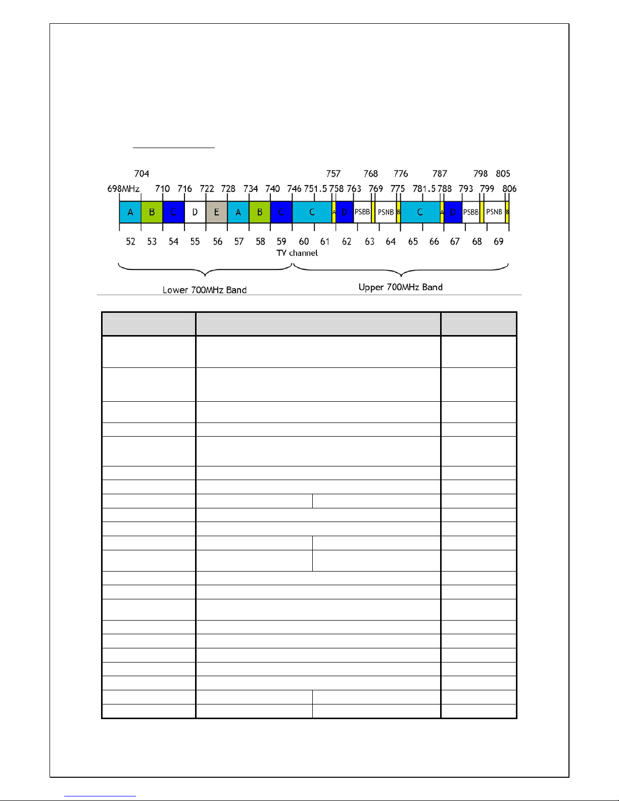
3.2.1. Frequency allocation
700MHz LTE Band
3.2.2. System Specifications
Item Specification Remarks
Tx Frequency Range A / B / Upper C band selection in 728 ~ 757MHz
Refer to band
allocation
Rx Frequency Range A / B / Upper C band selection in 698 ~ 787MHz
Refer to band
allocation
No of Carriers
Supported
1 CH LTE Carrier Max.
FWD Input Power -10 ~ 0dBm/total, -5dBm/total is recommended at MHU IN
FWD Output Power 40dBm/total for 700MHz RU ANT Port (MIMO0 / MIMO1)
RVS Input Power -50dBm/total max. at RU each ANT Port
RVS Output Power -20dBm/total max. at MHU each Rx ANT Port
System Gain FWD: 30dB ~ 50dB RVS:20dB ~ 30dB
FWD Spurious Comply to 3GPP, FCC regulation
RVS Noise Figure Comply to 17.5% of EVM by VzW test procedure
Gain Control Range FWD: 20dB by 1dB Step RVS: 20dB by 1dB Step RU OLC Gain
EVM (Error Vector
Magnitude)
FWD: 12.5% RVS: 17.5%
Frequency Stability 0.01ppm
Pass-Band Ripple 1dB max. Any CH
System Delay Max. 6usec
Without optical
cable
Tx0-Tx1 Isolation min. 40dBc
Tx0-Tx1 Isolation min. 40dBc
Tx-Rx Isolation 100dB min. @Between RU Tx Output and MHU Rx Output
Impedance 50 Ohm
VSWR 1.5 : 1 max. @ All input/output ports
Optical Wavelength FWD: 1570nm RVS: 1330nm
RF I/O Connector MHU: SMA-type Female RU: N-type Female
8 / 30
Kisan Telecom Confidential Proprietary
4. Mechanical Specifications
4.1. LMR250R01C RU
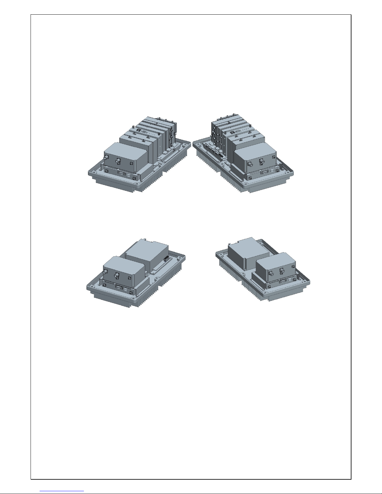
4.1.1. Mechanical Design
[RF SIDE]
[PSU SIDE]
9 / 30
Kisan Telecom Confidential Proprietary
[OUT SIDE 2D-Shape]
[OUT SIDE 3D-Shape]

10 / 30
Kisan Telecom Confidential Proprietary
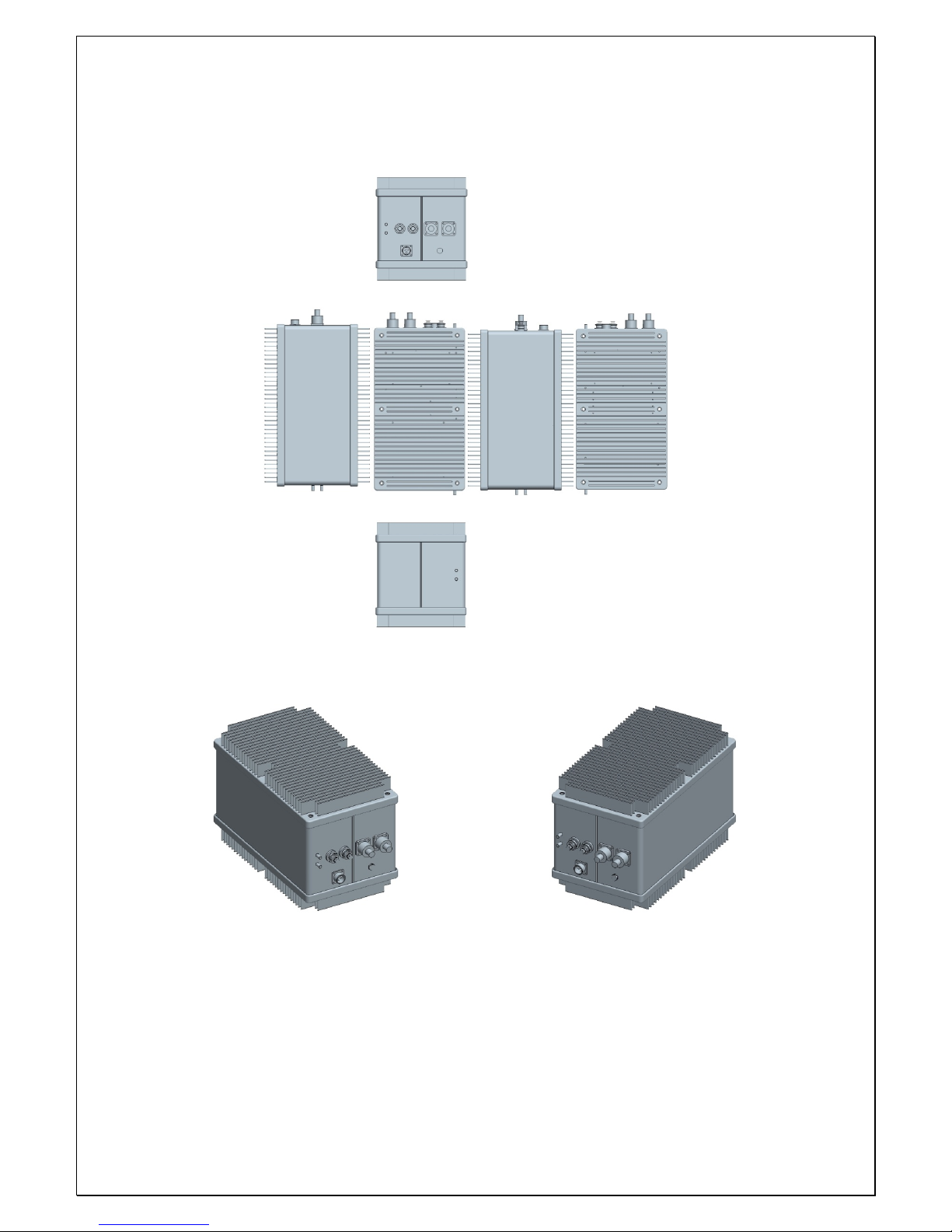
4.1.2. Dimension
RU System picture and Size 471.7(H) X 263.4(W) X 304.8(D) mm
[OutSide] [Inner Side] [Heat Sink Side]
4.1.3. Mechanical Specification
No Item Description
1 Dimension & Weight
Dimension: 471.7(H) X 263.4(W) X 304.8(D) mm
(plinth included)
Weight: 26 Kg
2 Method of Cooling Natural convection (Heat-sink)
3 Door Locking Type More than 10-point on each side using bolt lock
4 Optic Connector
Position: Cabinet inside
Connector type: SC/APC
5 ANT PORT
located at the side of cabinet
Connector Type: N Type Female
6 Power Input
Power: 110-120Vac, 60Hz
Position: the side of cabinet
Connector: MS connecter
7 Ground TBD
8 Waterproof condition Comply to IPx6
9 Misc. Features
Easy to deploy
Strand type (i.e., telegraph pole)
Convectional Heat Sink

11 / 30
Kisan Telecom Confidential Proprietary
4.1.4. Description of LMR250R01C RU
[Forward path]
The LTE FWD MIMO0, MIMO1 and modem combined signals sent from the optic
module of MHU is first divided into MIMO0, MIMO1 and modem signals at RFMUX in
RU, then the FWD RF signals are amplified and filtered at the RFBS0 and RFBS1 module.
The modem signal is conveyed to CPU of NMS controller through FSK modem. LTE
signal is reduced by the Crest Factor passing through the CFR FPGA digital board inside
RFBS0 and RFBS1. This technology enables reduction of PAPR for LTE signal increasing
HPA efficiency. A higher efficiency HPA allows using a smaller enclosure with lower
power consumption while decreasing OPEX for the service provider.
The LTE RF signals from the RFBS modules is linearly amplified up to high power level
on HPA, passed through the Front-End Filter Unit, and finally transmitted through a
coverage antenna.
[Reverse Path]
LTE Rx signals incoming from coverage antennas are first passed by the Front-End
Filter Unit, amplified by a low noise and high gain amplifier, filtered in RRBS and
RRBS1, and combined with modem signal and 10MHz at combiner(RRCOM). The
combined signal is then transmitted to MHU through the optic module.

12 / 30
Kisan Telecom Confidential Proprietary
4.1.5. Port Configuration
No Item Description
1 AC INLET 110V AC Power Cable Connection Port
2 MIMO0 ANT Port MIMO0 ANT RF Cable Connection Port
3 MIMO1 ANT Port MIMO1 ANT RF Cable Connection Port
4 Optical Cable INLET Optic cable connection Inlet
5 Goretex

13 / 30
Kisan Telecom Confidential Proprietary
4.1.6. Module Composition of RU
Module operational voltage table
No Module Voltage Used Remarks
1 RFMUX
2 RF FWD Band Selector for MIMO0 (RFBS0) 5.5Vdc /6.5Vdc
3 RF FWD Band Selector for MIMO1 (RFBS1) 5.5Vdc /6.5Vdc
4 Slave Optical Transceiver Unit (SOU) 6.5Vdc
5 RF Modem (FSK Modem) 9Vdc
6 RU RVS COM for Signal combing (RRCOM)
7 RU RVS Band Selector for MIMO0 (RRBS0) 6.5Vdc
8 RU RVS Band Selector for MIMO1 (RRBS1) 6.5Vdc
9 TX HPA for MIMO0 29Vdc
10 TX HPA for MIMO1 29Vdc
11 FE-Duplexer(Front-End Filter Unit) for MIMO0
12 FE-Duplexer(Front-End Filter Unit) for MIMO1
13 PSU (AC-DC) AC 110V INPUT
14 NMS Controller 9Vdc
15 Back Board Ass’y 5.5Vdc /6.5Vdc /9Vdc

14 / 30
Kisan Telecom Confidential Proprietary
4.1.7. Function of Modules
No Module Description
1
[Divider]
Divides signals into RF and modem signals and
sends to RFBS/RFCHS and FSK modem.
2
[RFBS0]
Controls the gain of TX0 path, filters FWD band,
controls the crest factor of TX0 signal, and
performs the ALC function. Output of the module
is sent to HPA.
3
[RFBS1]
Controls the gain of TX1 path, filters FWD band,
controls the crest factor of TX1 signal, and
performs the ALC function. Output of the module
is sent to HPA.
4
[SOU]
Performs E/O (or O/E) conversion for FWD and
RVS signals.
Wavelength: LD 1330[nm], PD 1570[nm]
5
[FSK Modem]
Data modem for RU and MHU communication
RU → MHU frequency: 340MHz
MHU → RU frequency: 360MHz
6
[RRCOM]
Combines RX0, RX1 and Modem signals, and
provides the combined signal to optical module
in order to perform E/O conversion.
7
[RRBS0]
Amplifies RX0 signal by low noise high gain,
filters for the desirable band and controls the
RVS path gain of RU.
8
[RRBS1]
Amplifies RX1 signal by low noise high gain,
filters for the desirable band and controls the
RVS path gain of RU.

15 / 30
Kisan Telecom Confidential Proprietary
9
[TX HPA for MIMO0]
16Watt(42dBm) High power amplifier built-in
linearizer amplifies the TX0 signal to high power
level and sends to RU ANT through the MIMO0
FE-Duplexer.
10
[TX HPA for MIMO1]
16Watt(42dBm) High power amplifier built-in
linearizer amplifies the TX1 signal to high power
level and sends to RU ANT through the MIMO1
FE-Duplexer.
11
[FE-Duplexer for MIMO0]
Front end duplexer that passes through TX0 and
RX0 frequency bands.
12
[FE-Duplexer for MIMO1]
Front end duplexer that passes through TX1 and
RX1 frequency bands.
13
[PSU]
Converts AC 110V to DC 29V/9V/6.5V/5.5V, and
distributes the necessary power to each modules.
14
[NMS Controller]
Monitors the status of modules in RU and
controls the configurable parameters of the RU
modules.
15
[Interface BD]
Provides operating voltage and monitors/controls
signal to modules connected to interface B’D.
Also provides a connection port to communicate
with NMS B’D.

16 / 30
Kisan Telecom Confidential Proprietary
Power Distribution Diagram

17 / 30
Kisan Telecom Confidential Proprietary
5. Block Diagram

18 / 30
Kisan Telecom Confidential Proprietary
6. Administration Program (RptMan-LMR250R01)
Administration program (RptMan-LMR250R01) is a management program for LMR250R01
and provides status monitoring and controlling functions to users.
6.1. System Requirement
System: Desktop or laptop PC
OS: Windows XP or later version
Resolution: 1024 768 or more
Connection Cable: 9 pin serial cable (cross type)
6.2. Cable connection
The cable connection between repeater and PC (GUI program) is illustrated below.
The NMS port of MHU provides two ports; one is a D-sub port for local GUI. The other
is an Ethernet port for NOC (Network Operating Center).
Repeater
NMS
port
D-Sub 9Pin
Female
2
3
5
D-Sub 9Pin Male
2
3
5
D-Sub 9Pin Female
PC GUI
Program
2
3
5
Ethernet port for NOC
D-sub port for GUI

19 / 30
Kisan Telecom Confidential Proprietary
6.3. Screen
Section Description
Window Title
Displays the name of management program(GUI), i.e. RptManLMR250R01.
Displays the type of equipment currently connected to the program
(MHU or RU).
Menu Bar
Presents working menu for operators.
It is associated with tool icons, which can activate the tool bar menus.
Toolbar
Presents icons (button type) for frequently used commands.
User-friendly icons are used.
Icons are activated or disabled as to the status of repeater.
Work Space
Status information and control functions are provided with a block
diagram view of MHU and RU.
Provides the working space for windows or dialogs.

20 / 30
Kisan Telecom Confidential Proprietary
6.4. Status Display
Status of repeater is displayed by LED’s and values.
LED
Alarm:
/ blinking indicates ALARM, indicates NORMAL
On/Off:
ON, OFF
Exception) for HPA,
is ON, is OFF
Value
Units are not displayed.
Value displayed in box (
)
Control
The shape of mouse cursor is changed to
on controllable parameters.
The texts of controllable LED or values are displayed in BOLD font.
6.5. Control Policy
System parameter can only be controlled one at a time.
Click a control item (button) to bring up a control popup dialog window.
Once a dialog popup window is opened, it stays there for repeated control until user
closes the window.
6.6. Menu
Menu Sub Menu Function
Connect Establishes connection between PC(GUI) and repeater
Disconnect Disconnects connection between PC(GUI) and repeater
File
Exit Finishes admin program.
Power Table Presents RF/Optic power table
TC Table Presents temperature compensation table
Action
Image Compression Compress the firmware file (executable file of repeater)
Showing a control range
Configurable Item
Target E q u i pm e n t.
(MHU or RU)

21 / 30
Kisan Telecom Confidential Proprietary
for download
MHU image download Downloads compressed firmware file to MHU equipment
RU image download Downloads compressed firmware file to RU equipment
Factory Setting Restores all parameter values to initial factory settings
System action Not available
Gain Setting
Tx: set ATT to have 30dBm on the remote ANT output.
Rx: set ATT to have 40dB of Rx total gain from RU to
MHU including optical loss.
Polling period Controls the polling period between PC and repeater
Block window Presents system window including MHU and RU
MHU Window Presents MHU status window in work space
View
RU Remote Window Presents RU status window in work space
Cascade
Tile Horizon
Cascade or tile horizon arrangement of repeater status
windows in work space
Arrange icons Arrange all icons under many window is opened
Close all Close all window
Window
Packet Debug
Presents debug window in workspace displaying packets
between repeater and GUI program
Help
About RptMan.Dual Displays the version information of GUI program, RptMan
(Repeater Manager)
6.7. Toolbar
ITEM ICON Function
Communication
Establishment
Establishes RS-232C connection to the repeater, then GUI
starts to communicate and status of repeater are polled and
displayed.
Communication
Disconnection
Disconnects communication with connected repeater.
Repeater status is not updated.
Polling
Stop/Resume
Stops or resumes polling action of GUI program. (activated
in toggling way)
Power Table
Presents RF/Optic power table
T/C table
Presents temperature compensation table
Debug Packet
Displays packet data between GUI and repeater like protocol
analyzer and it may help debugging of software
Compression of
image file
Compresses image file of repeater
Gain Setting
TX: set ATT to have 35dBm of output at the RU ANT Port
RX: set ATT to have 40dB gain of Rx path
Tx/Rx Gain setting function carry out Tx/Rx gain setting
including optical loss compensation automatically.

22 / 30
Kisan Telecom Confidential Proprietary
MHU Download
Download MHU firmware files to MHU equipment.
RU Download
Download RU firmware files to RU equipment.
MHU Factory
Setting
Initialize MHU parameters to factory setting values.
RU Factory
Setting
Restores RU parameters back to original factory setting
values.
Help
Shows version information
6.8. Program operation
6.8.1. Initiating communication
Function Establishing communication between GUI and repeater
Method
Click
button in toolbar of GUI program
Port Combo box to set the com port (COM1, COM2, …)
OK Button Initiates communication between GUI and repeater, then
closes this popup window(“Open Connection”)
When communication port is established correctly, you
can see the communication status by blinking icons.
(right-bottom side
of the main screen)
Description
Cancel Button Cancels and closes the popup window
6.8.2. Disconnect
Function Disconnecting GUI from repeater
Method
Click
button in toolbar of GUI program
Description The communication between GUI on PC and repeater becomes
disconnected.

23 / 30
Kisan Telecom Confidential Proprietary
6.8.3. LMR250R01 MHU Status Retrieval and Control
(1) Node Tree: This window displays the tree configuration of RUs connected with MHU
① MHU Press MHU to open the MHU screen
(1) Nose Tree
② RULTE/RUDUAL-1 ~ 6 Press VzWRU-# to open each RU screen
(2) MHU Screen window
① General & Environment
This part includes common parameter of MHU
like system information or environments
(2) MHU
Screen
② DOU Status/Control
This screen provides information on 6DOUs
LD Power & Lower limit value
PD Power & Lower limit value
Tx Input, Rx Output Power & Limit value
RU Install information

24 / 30
Kisan Telecom Confidential Proprietary
Group Description
Version: Firmware Versoin
Type: Repeater unit type
Name: ID of MHU for the communication
Gain Setting
TX: sets ATT to have 35dBm of output at the
RU ANT Port
RX: sets ATT to have 40dB gain of Rx path
Tx/Rx Gain setting function carries out Tx/Rx
gain setting including automatic optical loss
compensation.
User Connect: Connection status of COM port of
repeater
PSU: Status of PSU
TMPCUR: Current temperature of the equipment
TMPUPR: set the upper threshold value of
temperature (button) and alarm status (LED)
Install: This sets up the RU to communicate with
MHU. Even when an RU is connected to MHU
physically by optic cable, the RU cannot
communicate with MHU if RU is not installed
logically by GUI.
LD Power: Transmitted optical power level to RU
LD Lower: Lower limit level of the LD power
PD Power: Received optical power level from RU
PD Lower: Lower limit level of the PD power
TX Input: Tx level input from BTS
TX Upper: Upper limit of Tx input level
TX Lower: Lower limit of Tx input level
RX output: Rx level output to BTS
RX Upper: Upper limit of Rx output level
RX output: Rx level output to BTS
RX Upper: Upper limit of Rx output level
RX AGC ATT: RX path ATT for optic AGC
RU install: display the RU installation status
6.8.4. LMR250R01 RU Status Retrieval and Control

25 / 30
Kisan Telecom Confidential Proprietary
Group Description
Version: Firmware version
Type: Type of repeater
Name: Set the Name, ID, Serial No. of repeater RU
User Connect: Connection status of COM port of repeater
PSU: Status of PSU
TMPCUR: Current temperature in repeater RU
TMPUPR: Value/control of upper threshold of temperature
(button) and alarm status (LED)

26 / 30
Kisan Telecom Confidential Proprietary
LDPWR: Value of LD power (box) and status of LD (LED)
LDLWR: Value/control of lower threshold of LD power
(button) and lower alarm status of LD power (LED)
PDPWR: Value of PD power (box) and status of PD (LED)
PDLWR: Value/control of lower threshold of PD power
(button) and lower alarm status (LED)
RU parameters for TX0(MAIN)/TX1(MIMO) band are
displayed by the tab selection. Each band has the identical
items which can be monitored and controlled.
PLL: Alarm LED for 2 PLL’s
CFR On: On/Off status of Crest Factor Reduction function
CFR On: On/Off control the Crest factor reduction function
ATT: Sets ATT to control FWD gain, and shows its value.
Displayed ATT value = USR ATT + ALC ATT
USR ATT: This is the main FWD Gain setting point. It is used
for FWD auto gain setting or gain fine tuning
ALC ATT: When HPA output level is higher than ALC level it
automatically controls FWD gain to maintain output level
below HPA ALC level.
INPWR: Input total power level on CFR board
Center: Set the center frequency of FWD band by VzW
Frequency band A/B/Upper C.
On/Off: Status/control the operation state of HPA
OVTMP: Alarm status of HPA Over-temperature
OVPWR: Alarm status of HPA Over-Power
VSWR: Alarm status of HPA VSWR
OUT PWR: Output power level of HPA(box)
OUT UPR: Display/control of upper threshold of HPA output
power(button), alarm status(LED)

27 / 30
Kisan Telecom Confidential Proprietary
OUT LWR: Value/control of lower threshold of HPA output
power(button), alarm status(LED)
ALC: Set ALC level for HPA output, and shows ALC on/off
status of function(LED).
ASD(Auto Shutdown): ASD level(button), and shows ASD
on/off status of function(LED).
Protection On/Off: In order to protect RU from over input
RVS(Rx) signal power. In case that input signal is more than
IN UPR level, RU shuts down and LED is changed to RED.
And if input signal power is over than -45dBm, RU has the
10dB attenuation and MHU has the 10dB gain.
Pilot On/Off: Sets CW signal generation, and shows its
status. It is used for RVS gain setting.
IN PWR: RVS power value at the LNA output point
IN UPR: Sets RVS input upper threshold, and shows the
alarm status of input upper threshold.
OUTPWR: RVS RF output power of RRBS.
ATT: Sets ATT to control RVS gain, and shows it’s value.
Center Freq: It indicates pilot signal frequency value. This
value changes with FWD(Tx) center frequency automatically.

28 / 30
Kisan Telecom Confidential Proprietary
6.8.5. Firmware download
Firmware download is performed when system needs to be updated.
Downloading improper images (executable file of repeater CPU) may cause harmful
damages to equipment.
The following steps should be taken for firmware download.
① Convert firmware source file (*.bin) to a downloadable file format.
Main menu: Action → Image Compression, toolbar:
② Open a pop-up window showing the status of the target equipment for firmware
download.
Step 1) Main menu View ¡æ Select Donor Windows or Remote Windows
Step 2) In Block View Dialog window, select Donor Windows or Remote Windows
③ Download firmware to the target equipment.
Step 1) Main menu Action ¡æ select Image Download menu
Step 2) In toolbar, select
for MHU, and select for RU
Download firmware after selecting the firmware file for the target equipment.
File conversion procedure
Select target file
Perform function
Store modified
Select target file

29 / 30
Kisan Telecom Confidential Proprietary
Download procedure
6.9. Additional features
6.9.1. ASD (Auto Shutdown) Function
1. If the power level is above the shut down level for longer than 1 second, turn off
HPA.
2. During shutdown state, monitor RU input power. If the level is below 5dB from shut
down level, turn on HPA automatically.
3. Monitor HPA output power in normal operation, and monitor RU input power during
shut down.
Display selected file information
Display progress of firmware download
Select file
Perform operation
Longer than 1 sec, HPA off

30 / 30
Kisan Telecom Confidential Proprietary
6.9.2. ALC (Auto Level Control) Function
1. If the power level reaches the ALC level, prevent from transmitting higher than ALC
level by using ATT control.
2. By storing the existing ATT value, the ATT value before ALC can be reused even
when the power is reduced.
No ATT change
ATT increase(Gain decrease)
 Loading...