

Kisae SWXFR1210, SWXFR1220, SWXFR1230, SWXFR1210i, SWXFR1230i Owner's Manual
...
Sinewave Inverter
with Transfer Switch
120V Model
1000W (SWXFR1210)
2000W (SWXFR1220)
3000W (SWXFR1230)
230V Model
1000W (SWXFR1210i)
2000W (SWXFR1220i)
3000W (SWXFR1230i)
Owner’s Manual

For safe and optimum performance, the KISAE Sinewave Inverter with Transfer Switch must be used
properly. Carefully read and follow all instructions and guidelines in this manual and give special
attention to the CAUTION and WARNING statements.
PLEASE KEEP THIS MANUAL FOR FUTURE REFERENCE
Disclaimer
While every precaution has been taken to ensure the accuracy of the contents of this guide, KISAE
Technology assumes no responsibility for errors or omissions. Note as well that specifications and
product functionality may change without notice.
Important
Please be sure to read and save the entire manual before using your KISAE Sinewave Inverter
with Transfer Switch unit. Misuse may result in damage to the unit and/or cause harm or serious
injury.
Product Numbers:
120V model:
SWXFR1210 Sinewave Inverter 1000W with Transfer Switch (US Socket - NEMA 5-15)
SWXFR1220 Sinewave Inverter 2000W with Transfer Switch (US Socket - NEMA 5-20)
SWXFR1230 Sinewave Inverter 3000W with Transfer Switch (US Socket - NEMA 5-20)
230V model:
SWXFR1210i-UK Sinewave Inverter 1000W with Transfer Switch (British Socket-BS1363)
SWXFR1210i-EU Sinewave Inverter 1000W with Transfer Switch (Schuko Socket-CEE 7/4)
SWXFR1210i-AU Sinewave Inverter 1000W with Transfer Switch (Australia Socket-NS/NZS 3112)
SWXFR1220i-UK Sinewave Inverter 2000W with Transfer Switch (British Socket-BS1363)
SWXFR1220i-EU Sinewave Inverter 2000W with Transfer Switch (Schuko Socket-CEE 7/4)
SWXFR1220i-AU Sinewave Inverter 2000W with Transfer Switch (Australia Socket-NS/NZS 3112)
SWXFR1230i-UK Sinewave Inverter 3000W with Transfer Switch (British Socket-BS1363)
SWXFR1230i-EU Sinewave Inverter 3000W with Transfer Switch (Schuko Socket-CEE 7/4)
SWXFR1230i-AU Sinewave Inverter 3000W with Transfer Switch (Australia Socket-NS/NZS 3112)
Document Part Number
MUXFR 1210RevC
Service Contact Information
Email: info@kisaetechnology.com
Phone : 1-877-897-5778
Web : www.kisaetechnology.com
Page 2

Table of Contents
1. INTRODUCTION................................................................................................ 4
2. PRODUCT DESCRIPTION............................................................................... 5
3. INSTALLATION.................................................................................................5
4. UNIT OPERATION........................................................................................... 11
5. FEA TURE SETTING........................................................................................ 13
6. TROUBLESHOOTING.................................................................................... 15
6. SPECIFICATIONS........................................................................................... 18
7. WARRANTY..................................................................................................... 19
APPENDIX I.............................................................................................................. 20
APPENDIX II............................................................................................................. 20
Page 3

1. INTRODUCTION
Thank you for purchasing the KISAE Sinewave Inverter with Transfer Switch unit. With our
state of the art, easy-to-use design, this product will offer you reliable service by providing AC
power and 5V USB power for your home, cabin, boat, RV, Caravan or Trailer using battery power.
The Sinewave Inverter can run many AC-powered appliances when you need AC power from a
battery source. The 5V USB power can charge many USB-powered devices. The inverter also will
automatically switch to utility AC power when it is available at your home, dock or campsite.
This manual will explain how to use this unit safely and effectively. Please read and follow these
instructions and precautions carefully.
IMPORTANT SAFETY INFORMATION
This section contains important safety information for the Sinewave Inverter. Before using the
unit, READ ALL instructions and cautionary markings on or provided with the unit, and all
appropriate sections of this guide.
The Sinewave Inverter contains no user-serviceable parts. See Warranty section for how to
handle product issues.
DANGER:
• Do not cover or obstruct any air vent openings and/or install in a zero-clearance compartment.
DANGER:
• When working with electrical equipment or lead acid batteries, have someone nearby in case of
an emergency.
• Study and follow all the battery manufacturer’s specific precautions when installing, using and
servicing the battery connected to the inverter.
• Wear eye protection and gloves.
• Avoid touching your eyes while using this unit.
• Keep fresh water and soap on hand in the event battery acid comes in contact with eyes. If this
occurs, cleanse right away with soap and water for a minimum of 15 minutes and seek medical
attention.
• Batteries produce explosive gases. DO NOT
system.
• Keep unit away from moist or damp areas.
• Avoid dropping any metal tool or object on the battery. Doing so could create a spark or short
circuit which goes through the battery or another electrical tool that may create an explosion.
DANGER: Shock Hazard. Keep away from children!
• Avoid moisture. Never expose unit to snow, water etc.
• Unit provides household AC output; treat the AC output socket the same as regular wall AC
sockets at home.
DANGER
• DO NOT use the unit in the vicinity of flammable fumes or gases (such as propane tanks or
large engines).
• AVOID covering the ventilation openings. Always operate unit in an open area.
• Prolonged contact to high heat or freezing temperatures will decrease the working life of the unit.
• DO NOT connect AC power source like utility power or generator to the AC outputs of the unit. It
will damage the unit and may cause fire. Feeding AC to the AC output of the unit is not covered
by warranty.
FCC and CE EMC INFORMATION
This equipment has been tested and found to comply with the limits for a Class B digital device,
pursuant to part 15 of the FCC Rules on 120V model and comply with the limits for CE EMC
Standard on 230V model. These limits are designed to provide reasonable protection against
Fire and/or Chemical Burn Hazard.
Failure to follow these instructions can result in death or serious injury.
smoke or have an open spark or fire near the
: Explosion hazard!
Page 4
harmful interference in a residential installation. This equipment generates uses and can radiate
radio frequency energy and, if not installed and used in accordance with the instructions, may
cause harmful interference to radio communications. However, there is no guarantee that
interference will not occur in a particular installation. If this equipment does cause harmful
interference to radio or television reception, which can be determined by turning the equipment off
and on, the user is encouraged to try to correct the interference by one or more of the following
measures:
• Re-orient or relocate the receiving antenna.
• Increase the separation between the equipment and the receiver.
• Connect the equipment into an outlet on a circuit different from that to which the receiver is
connected.
• Consult the dealer or an experienced radio/TV technician for help.
LIMITATIONS ON USE
Do not use in connection with life support systems or other medical equipment or devices.
2. PRODUCT DESCRIPTION
The Sinewave Inverter includes the items list below.
• Inverter with transfer switch base unit with detachable Remote Panel
• Remote Panel Cable
• Owner’s Manual
Series Model No.
120 VAC
SWXFR1220 2000W
SWXFR1210 1000W 15A GFCI, Hardwire
SWXFR1230 3000W
230 VAC
SWXFR1220i 2000W
SWXFR1210i 1000W
SWXFR1230i 3000W
Inverter Transfer Switch
Rating
30A
16A
AC Output Types
20A GFCI, Hardwire
16A(EU-Schuko), Hardwire
13A(UK-British), Hardwire
10A(AU-Australia), Hardwire
3. INSTALLATION
WARNING: All wiring should be done by a certified technician or electrician to ensure
adherence to the applicable electrical safety wiring regulations and installation codes.
Failure to follow these instructions can damage the unit and could also result in personal
injury or loss of life.
CAUTION: Before beginning unit installation, please consider the following:
• The unit should be used or stored in an indoor area away from direct sunlight, heat, moisture
or conductive contaminants.
• When placing the unit, allow a minimum of three inches of space around the unit for optimal
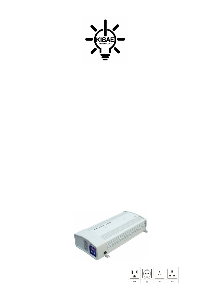
AC Output Front Panel
Hard Wired AC Output Port2
Hard Wired AC Output Port 1
Common (Input/Output) AC
ventilation.
Understanding the unit features
AC Wiring Compartment:
AC Output strain relief
AC Input strain relief
AC Input port
Ground
Model SWXFR1210
Page 5
USB Output
Status Indicator
Display
On/Off button
15A thermal breaker for the GFCI
Socket & AC Output L2 (Port 2)
Select button
AC Output GFCI Socket
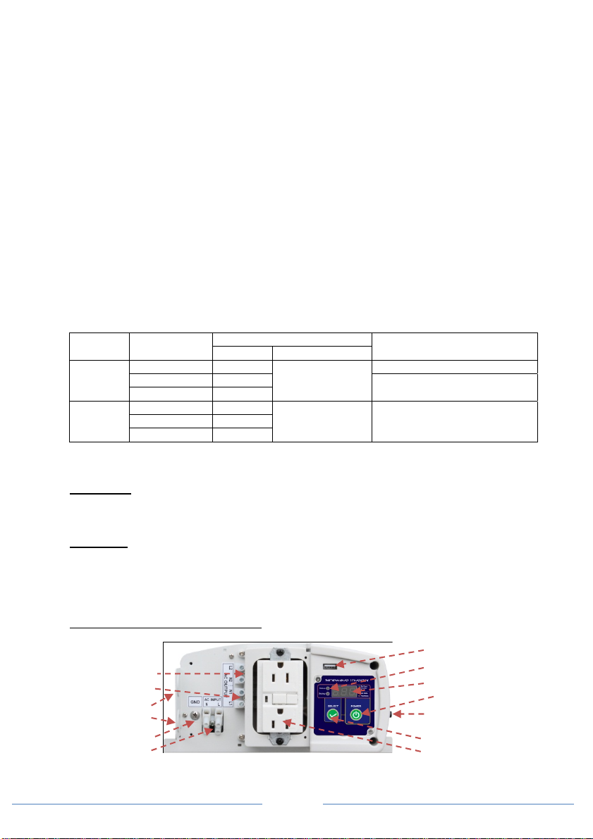
AC Wiring Compartment:
Hardwired AC Output Port 2
Hardwired AC Output Port 1
AC Output strain relief
AC Input strain relief
Common (Input/Output)AC
AC Wiring Compartment:
Hardwired AC Output Port2
Ground Port GP1 & GP2
AC Output strain relief
AC Input strain relief
Common (Input/Output)AC
DC Input Rear Panel
Ground
AC Input port
Ground
AC Input port
Fan
opening
Model SWXFR1220, SWXFR1230
Model SWXFR1210i-EU, SWXFR1220i-EU, SWXFR1230i-EU
USB Output
Status Indicator
Display
On/Off button
20A thermal breaker for the GFCI
Socket and AC Output L2 (Port 2)
Select button
AC Output GFCI Socket
USB Output
Status Indicator
Display
On/Off button
Thermal Breaker for AC Output
Socket
Select button
AC Output Socket
DC Input Terminals
Model SWXFR1210/1220/1210i/1220i
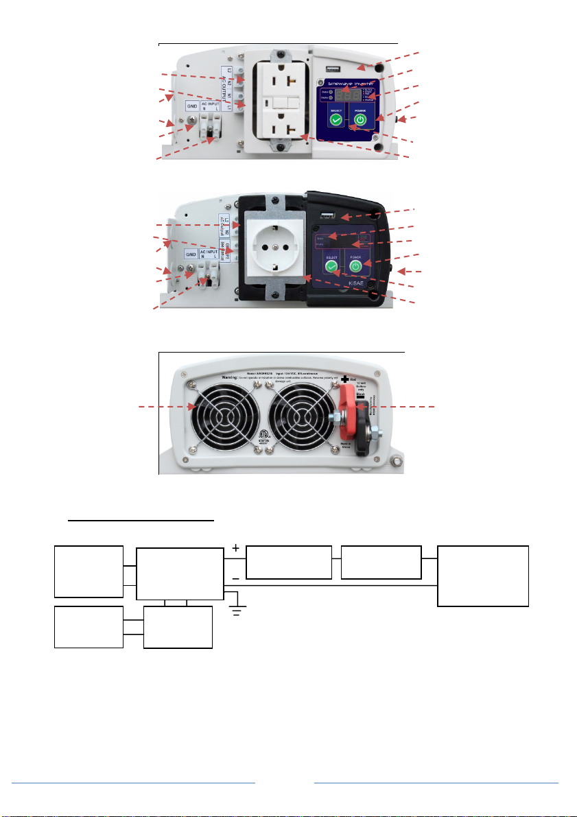
Preparing for Installation
Typical Wiring block diagram of the Power Inverter:
AC Output
Ports &USB
Output
AC Input
Source
Inverter with
Transfer Switch
Unit
AC Input
Branch
Breaker
12V Battery Bank:
• The use of a deep cycle battery is highly recommended for power inverter application
• For battery sizing, you need to identif y what you wish to operate, and for how long. It is
recommended that you purchase as much battery capacity as possible. See more on Battery
Run Time in Section 4.
DC Fuse or Circuit Breaker:
• DC-rated fuse or DC-rated circuit breaker connected along the DC positive line is required.
DC Disconnect
Switch
Page 6
DC Fuse or
Circuit Breaker
12 V Battery Bank
 Loading...