

Kisae IC1220100, IC1230150, IC244090i Owners Manual/install Manual

A
bso Sinewave
Inverter-Charger
2000W
(IC1220100)
3000W
(IC1230150)
4000W (IC244090i)
Owner’s Manual

Page 2
For safe and optimum performance, the KISAE Abso Inverter-Charger must be used properly.
Carefully read and follow all instructions and guidelines in this manual and give special attention to the
CAUTION and WARNING statements.
PLEASE KEEP THIS MANUAL FOR FUTURE REFERENCE
Disclaimer
While every precaution has been taken to ensure the accuracy of the contents of this guide, KISAE
Technology assumes no responsibility for errors or omissions. Note as well that specifications and
product functionality may change without notice.
Important
Please be sure to read and save the entire manual before using your KISAE Inverter-Charger.
Misuse may result in damage to the unit and/or cause harm or serious injury. Read manual in its
entirety before using the unit and save manual for future reference.
Product Numbers
IC1230150
Abso Inverter-Charger 3000
(12V – 120VAC)
IC1220100
Abso Inverter-Charger 2000
(12V – 120VAC)
IC244090i
Abso Inverter-Charger 4000
(24V – 230VAC)
Document Part Number
MUIC1230 Rev B
Service Contact Information
Email: info@kisaetechnology.com
Phone : 1 877 897-5778
Web : www.kisaetechnology.com

Page 3
IMPORTANT SAFETY INFORMATION
This section contains important safety information for the unit. Each time, before using the unit, READ
ALL instructions and cautionary markings on or provided with the unit, and all appropriate sections of
this guide.
The unit contains no user-serviceable parts. See Warranty section for how to handle product issues.
DANGER: Fire and/or Chemical Burn Hazard. Failure to follow these instructions can
result in death or serious injury!
• Do not cover or obstruct any air vent openings and/or install in a zero-clearance compartment.
• When working with electrical equipment or lead acid batteries, have someone nearby in case of an
emergency.
• Study and follow all the battery manufacturer’s specific precautions when installing, using and
servicing the battery connected to the inverter unit.
• Wear eye protection and gloves.
• Avoid touching your eyes while using this unit.
• Keep fresh water and soap on hand in the event battery acid comes in contact with eyes. If this occurs,
cleanse right away with soap and water for a minimum of 15 minutes and seek medical attention.
• Batteries produce explosive gases. DO NOT
smoke or have an open spark or fire near the system.
• Keep unit away from moist or damp areas.
• Avoid dropping any metal tool or object on the battery. Doing so could create a spark or short circuit
which goes through the battery or another electrical tool that may create an explosion.
DANGER: Shock Hazard. Keep away from children!
• Avoid moisture. Never expose unit to snow, water etc.
• Unit provides household AC, treat the AC output the same as regular wall AC sockets at home.
DANGER: Explosion hazard!
• DO NOT use the unit in the vicinity of flammable fumes or gases (such as propane tanks or large
engines).
• AVOID covering the ventilation openings. Always operate unit in an open area.
• Prolonged contact to high heat or freezing temperatures will decrease the working life of the unit.
FCC INFORMATION
This equipment has been tested and found to comply with the limits for a Class B digital device,
pursuant to part 15 of the FCC Rules. These limits are designed to provide reasonable protection
against harmful interference in a residential installation. This equipment generate, uses and can radiate
radio frequency energy and, if not installed and used in accordance with the instructions, may cause
harmful interference to radio communications. However, there is no guarantee that interference will not
occur in a particular installation. If this equipment does cause harmful interference to radio or television
reception, which can be determined by turning the equipment off and on, the user is encouraged to try to
correct the interference by one or more of the following measures:
• Reorient or relocate the receiving antenna.
• Increase the separation between the equipment and the receiver.
• Connect the equipment into an outlet on a circuit different from that to which the receiver is connected.
• Consult the dealer or an experienced radio/TV technician for help.
LIMITATIONS ON USE
Do not use in connection with life support systems or other medical equipment or devices.

Page 4
Table of Contents
1. INTRODUCTION................................................................................................ 5
2. PRODUCT DESCRIPTION............................................................................... 5
3. INSTALLATION ................................................................................................. 6
4. UNIT OPERATION........................................................................................... 12
5.
FEATURE SETTING........................................................................................ 15
6. TROUBLESHOOTING.................................................................................... 16
7. SPECIFICATIONS........................................................................................... 17
8. WARRANTY..................................................................................................... 18
Page 5
1. INTRODUCTION
Thank you for purchasing the KISAE Abso Inverter-Charger. With our state of the art,
easy to use design, this product will offer you reliable service by providing AC power for your home,
cabin, boat, RV, Caravan or Trailer and recharge your battery automatically when utility AC is
available. The unit can run many AC-powered appliances when you need AC power anywhere.
The multi-stage battery charger will charge different types of batteries. The transfer switch will
automatically switch the load to the battery power when the utility power is interrupted.
Feature Highlights
• The unit provides true sinewave output power for your microwave, entertainment system,
computer and other loads. The AC output power is identical to the AC power provided by the
utility grid. It can handle sensitive loads such as dimmer switches and appliances with speed
controls.
• High surge power to start difficult load like sump pumps, refrigerators, or A/C compressors.
• The battery charger has high output, multi-stage charging capability to minimize charging time.
The Power Factor Corrected (PFC) input minimizes AC input current required for charging.
• Optional Batter y Temperature Sensor (BTS) is available and used to sense the battery
temperature to correct charging voltage to ensure the battery is fully charged.
• A manual Equalization Mode is built-in to improve the life and performance of flooded batteries.
• The charger can charge dead batteries as low as 7 volts on 12V models and 14 volts on 24V
models.
• During utility mode, the built-in AC load sensing circuit will automatically reduce charging current
if there is a high demand on AC load. This avoids the tripping of the shore circuit breaker.
2. PRODUCT DESCRIPTION
The KISAE Abso Inverter-Charger includes the items list below.
• Inverter-Charger base unit
• Remote Display
• 25 ft (7.6 m) remote display cable
• Owner’s manual (P/N: MU IC 1230)
Model Inverter Charger
IC1220100 2000W - 120 VAC 12V - 100A
IC1230150 3000W - 120 VAC 12V - 150A
IC244090i 4000W - 230 VAC 24V - 90A
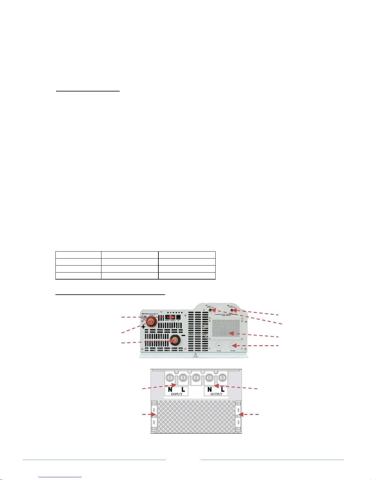
Understanding the unit features
IC1220100
Front Panel
AC Wiring Compartment
Remote 1, Remote 2 and
Battery Temperature Sensor
(BTS) Ports
DC Input Terminal +
DC Input Terminal -
AC Output Breaker (20A )
AC Input Breaker (30A)
AC Wiring Compartment
AC Wire knockouts
AC Output
AC GND bus
for AC Output
AC Input
AC GND bus
for AC Input
Page 6
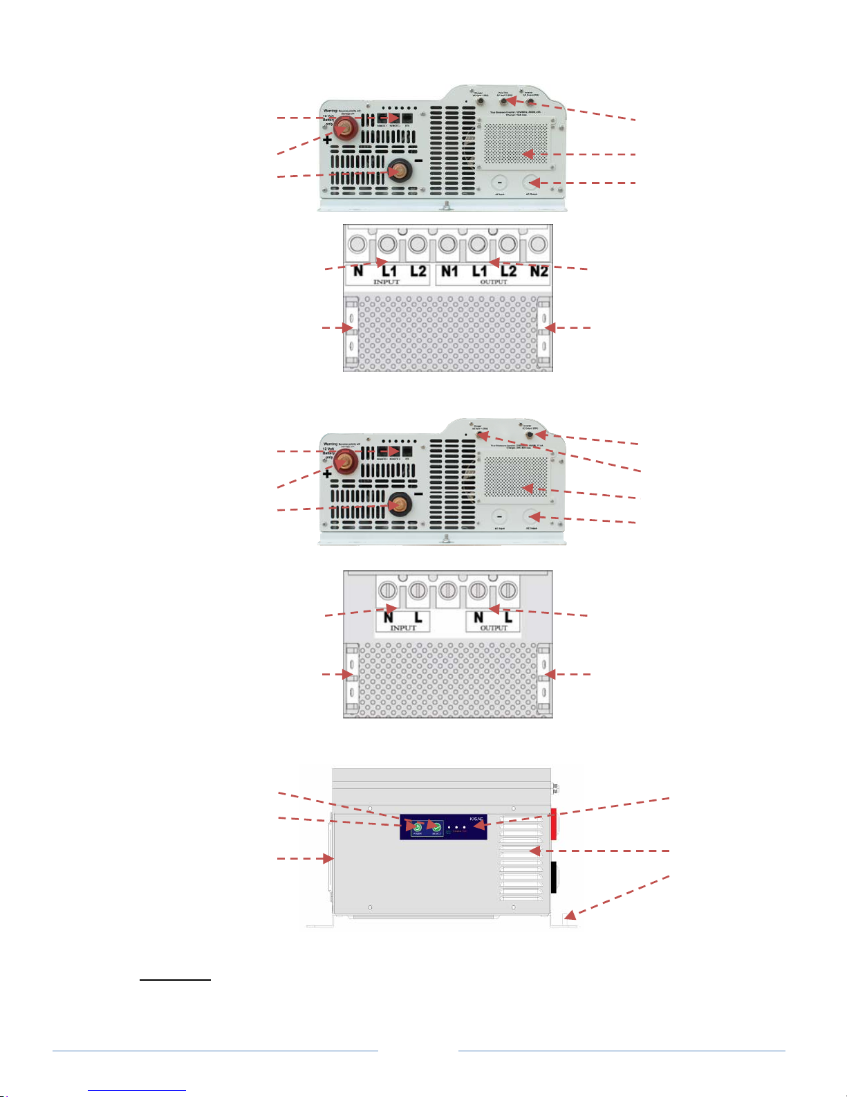
IC1230150
Front Panel
AC Wiring Compartment
IC244090i
Front Panel
AC Wiring Compartment
Control Panel
3. INSTALLATION
WARNING: All wiring should be done by a certified technician or electrician to ensure
adherence to the applicable electrical safety wiring regulations and installation codes.
Failure to follow these instructions can damage the unit and could also result in
Reset button
Power button
Fan opening
Status Indicator
Ventilation
Unit GND Stud
Remote 1, Remote 2 and
Battery Temperature Sensor
(BTS) Ports
DC Input Terminal +
DC Input Terminal -
AC Input and Output
Breaker (30A)
AC Wiring
Compartment
AC Wire knockouts
AC Output 1 and 2
AC GND bus for AC
Output 1 and 2
AC Input 1 and 2
AC GND bus for AC
Input 1 and 2
Remote 1, Remote 2 and
Battery Temperature Sensor
(BTS) Ports
DC Input Terminal +
DC Input Terminal -
AC Output
AC GND bus for AC
Output 1 and 2
AC Input
AC GND bus for AC
Input 1 and 2
AC Output Breaker (20A )
AC Input Breaker (20A)
AC Wiring Compartment
AC Wire knockouts
 Loading...