

Kisae DMT1230, DMT1250 Owner's Manual
Abso DC to DC
Battery Charger
12V 30A (DMT1230)
12V 50A (DMT1250)
Owner’s Manual

Page 2
For safe and optimum performance, the KISAE Abso DC to DC Battery Charger must be used properly.
Carefully read and follow all instructions and guidelines in this manual and give special attention to the
CAUTION and WARNING statements.
PLEASE KEEP THIS MANUAL FOR FUTURE REFERENCE
Disclaimer
While every precaution has been taken to ensure the accuracy of the contents of this guide, KISAE
Technology assumes no responsibility for errors or omissions. Note as well that specifications and
product functionality may change without notice.
Important
Please be sure to read and save the entire manual before using your KISAE DC to DC Battery
Charger. Misuse may result in damage to the unit and/or cause harm or serious injury.
Product Numbers
DMT1230 Abso DC to DC Battery Charger 12V 30A
DMT1250 Abso DC to DC Battery Charger 12V 50A
Document Part Number
MU DMT1230 Rev B
Service Contact Information
Email: info@kisaetechnology.com
Phone : 1 877 897-5778
Web : www.kisaepower.com

Page 3
Table of Contents
1. INTRODUCTION .................................................................................................. 6
2. PRODUCT DESCRIPTION ................................................................................. 6
3. UNDERSTANDING THE UNIT ............................................................................ 6
4. INSTALLING THE CHARGER ............................................................................ 8
5. UNIT OPERATION ............................................................................................. 10
6. SPECIFICATIONS .............................................................................................. 17
7. WARRANTY ....................................................................................................... 18
Appendix A1
Appendix A2
Appendix A3

Page 4
IMPORTANT SAFETY INFORMATION
This section contains important safety information for the KISAE Abso DC to DC Battery
Charger. Each time, before using the unit, READ ALL instructions and cautionary markings on or
provided with the unit, and all appropriate sections of this guide. The unit contains no userserviceable parts. See Warranty section for how to handle product issues.
WARNING: Fire and/or Chemical Burn Hazard!
Do not cover or obstruct any air vent openings and/or install in a zero-clearance compartment.
WARNING: Failure to follow these instructions can result in death or serious injury. Keep away
from children!
When working with electrical equipment or lead acid batteries, have someone nearby in case of an
emergency.
Study and follow all the battery manufacturer’s specific precautions when installing, using and
servicing the battery connected to the charger.
Wear eye protection and gloves.
Avoid touching your eyes while using this unit.
Keep fresh water and soap on hand in the event battery acid comes in contact with eyes. If this
occurs, cleanse right away with soap and water for a minimum of 15 minutes and seek medical
attention.
Batteries produce explosive gases. DO NOT smoke or have an open spark or fire near the system.
Keep unit away from moist or damp areas. Never expose unit to snow, water etc.
Avoid dropping any metal tool or object on the battery. Doing so could create a spark or short circuit
which goes through the battery or another electrical tool that may create an explosion.
WARNING: Explosion hazard!
Do not use the unit in the vicinity of flammable fumes or gases (such as propane tanks or large
engines).
Avoid covering the ventilation openings. Always operate unit in an open area.
Prolonged contact to high heat or freezing temperatures will decrease the working life of the unit.
CAUTION:
This appliance is not intended for use by persons (including children) with reduced physical,
sensory or mental capabilities, or lack of experience and knowledge, unless they have been given
supervision or instruction concerning use of the appliance by a person responsible for their safety.
Children should be supervised to ensure that they do not play with the appliance.
Do not charge non-rechargeable batteries because of the danger of eruption.
During charging, batteries should be placed in a ventilated area.
The battery terminal not connected to the chassis has to be connected first.
The other connection is to be made to the chassis, remote from the battery and fuel line. The
battery charger is then to be connected to the supply mains (household power).
After charging, disconnect the battery charger from the supply mains. Then remove the chassis
connection and then the battery connection.
Only allow children at least 8 years old to use the battery charger. Give sufficient instruction so that
the child is able to use the battery charger in a safe way and explain that it is not a toy and must not
be played with.
Examine the battery charger regularly for damage, especially the cord, plug and enclosure. If the
battery charger is damaged, it must not be used until it has been repaired.

Page 5
FCC INFORMATION
This equipment has been tested and found to comply with the limits for a Class B digital device,
pursuant to part 15 of the FCC Rules. These limits are designed to provide reasonable protection
against harmful interference in a residential installation. This equipment generates uses and can
radiate radio frequency energy and, if not installed and used in accordance with the instructions, may
cause harmful interference to radio communications. However, there is no guarantee that interference
will not occur in a particular installation. If this equipment does cause harmful interference to radio or
television reception, which can be determined by turning the equipment off and on, the user is
encouraged to try to correct the interference by one or more of the following measures:
• Re-orient or re-locate the receiving antenna. Re-orient or re-locate
• Increase the separation between the equipment and the receiver.
• Connect the equipment into an outlet on a circuit different from that to which the receiver is
connected.
• Consult the dealer or an experienced radio/TV technician for help.
LIMITATIONS ON USE
Do not use in connection with life support systems or other medical equipment or devices.

Page 6
1. INTRODUCTION
Thank you for purchasing the KISAE Abso DC to DC Battery Charger. With our state of the art,
easy to use design, this product will offer you reliable service for providing a multi-stage, multiinput battery charger to charge the different types of batteries you have installed in either your
home, boats, RV caravan, 4WD or commercial vehicle. This manual will explain how to use this
unit safely and effectively.
2. PRODUCT DESCRIPTION
The DC to DC Battery Charger includes the items list below:
Base unit
Owner’s manual
Model
Output Rating
DMT1230
12V 30A
DMT1250
12V 50A
3. UNDERSTANDING THE UNIT
The DC to DC Battery Charger is a fully automatic multi-stage, multi-input battery charger with the
ability to charge from either an alternator linked to a battery, or via solar power with the Maximum
Power Point Tracking (MPPT) Solar Controller. With two inputs available, the house battery will
be charged from either the engine while underway, or via the solar panels when stationary. The
process to choose either engine or solar is fully automatic and both functions are controlled from
within the unit itself without the need for external relays.
During normal operation the DC to DC Battery Charger will do a full charge cycle to float stage on
the house battery bank with ability to choose either GEL, AGM, Flooded, Custom Programmable
or Lithium. Once float stage is reached the charger transitions to a power supply mode to support
any on-board DC loads.
Multi-stage Charging Process – GEL, AGM, Flooded & Program Modes
The DC to DC Battery Charger is a fully automatic, set and forget charger. It is designed to
quickly and accurately recharge your deep cycle batteries utilizing charger algorithms that help to
maximize the life of your specialized deep cycle batteries.
The DC to DC Battery Charger features multi-stage smart charging technology that enables the
charger to be connected to your battery bank permanently. With the input of multiple sources, you
can be assured of charging your batteries whenever underway; or when the sun is shining on
your solar array.
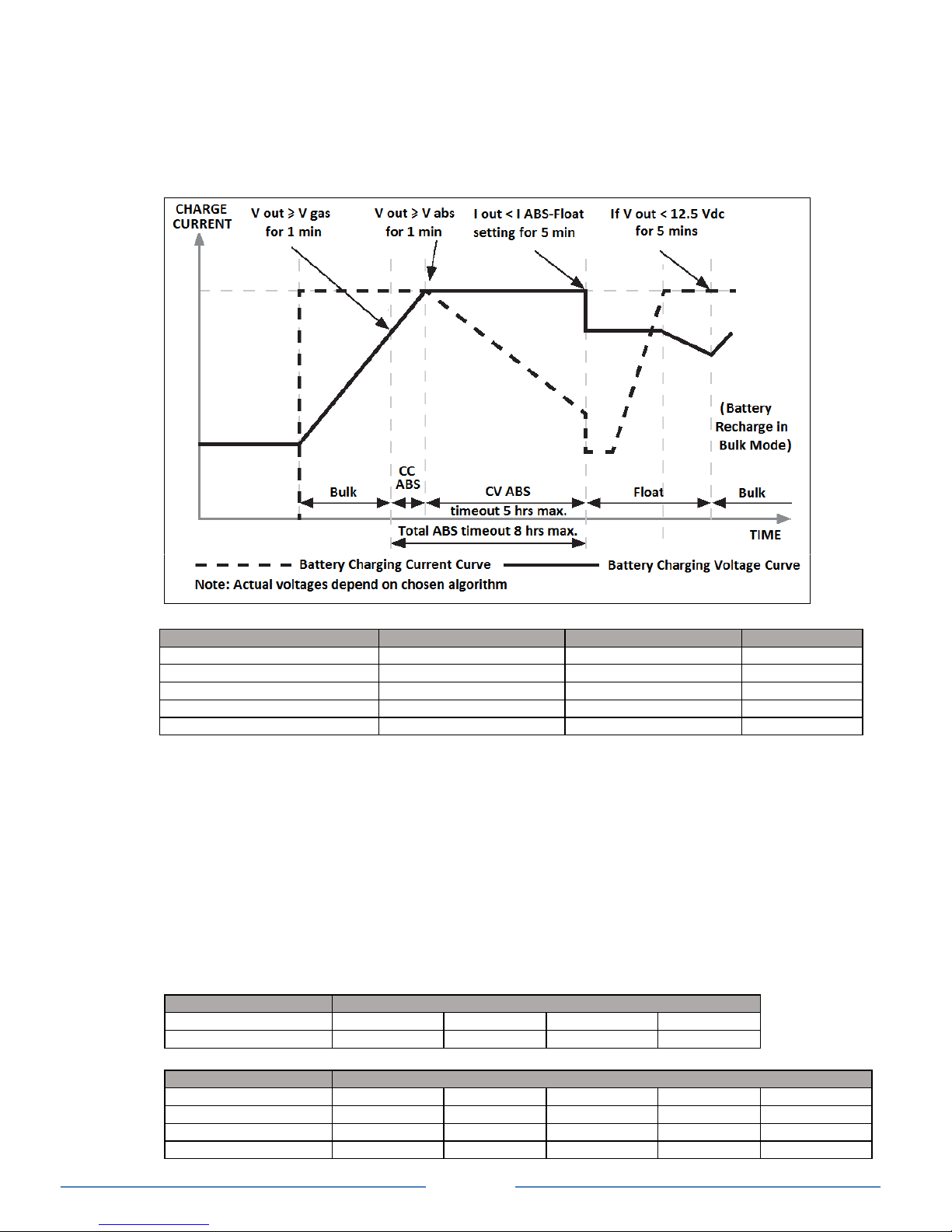
As dictated by battery manufactures recommendations, deep cycle batteries require a multi-stage
charge sequence for perfect, fast and accurate charging. The DC to DC Battery Charger delivers
three primary charge stages.
Stage 1 – Bulk or Boost charge: The battery is charged at full rated output current of the charger until the
battery reaches its final charging voltage, known as its absorption voltage. In this step, around 80%
of the battery is recovered as fast as possible.
Stage 2 – Absorption Charge: With the charger voltage held steady, the remaining 20% is replaced with the
charger allowing the current to taper off as the battery approaches full charge.
Stage 3 – Float: Finally, in the float stage the charger voltage is lowered and held at a constant and safe
predetermined level. This prevents the battery from being overcharged, yet allows the charger to
supply enough current to make up for the self-discharge losses of the battery, while supporting any
additional loads connected to the battery (such as DC lighting and refrigerators). This stage allows
for the charger to be used as a DC power supply.
Lithium Charging Process
The DC to DC Battery Charger has a specific charging profile for Lithium batteries. It has its own
charging voltage and current settings that needs to be set by the user. It also requires the user to
set the charger termination current (“L” setting). Once the user defined charge voltage is reached,
the charger will start reducing the current output and the charging process will terminate when the
charging current drops to the set termination current. This can take anywhere between 3 to 15
minutes. The unit will then act as a power supply to support additional loads connected to the
battery while the DC to DC Battery charger powered from either the vehicle or solar inputs. A Bulk
re-start will occur when battery voltage drops below 13.3V DC.
Page 7
Smart Charging Feature
The DC to DC Battery Charger will regulate its output based on the loads connected to your
battery banks. This function is important to maintain the life of your battery banks as some battery
chargers mistake loads for discharge and continue to keep the batteries in the bulk or absorption
stage for extended periods of time, which will damage the battery bank. The DC to DC Battery
Charger has two methods of load-based regulation to ensure your battery charger transitions to
float stage when it should do so.
GEL, AGM, Flooded & Program Batteries Charging Algorithm
Battery Charger Voltage
Battery Type
Bulk/Absorption
Float (Note 1)
Equalization
GEL
14.4V
13.7V
N.A.
AGM
14.6V
13.6V
N.A.
Flooded
14.4V
13.3V
15.5V (Note 2)
Lithium (Note 3)
13.9-14.6V (0.1V step)
13.5-14.2V (0.1V step)
N.A.
Program (Custom Settings)
13.8-14.8V (0.1V step)
13.0-13.8V (0.1V step)
N.A.
For Concorde™ branded batteries (lifeline, sun xtender) use flooded setting and consult battery supplier for
equalization recommendations.
Note 1: Charger is acting as a power supply with selected constant output voltage and preset maximum
output current.
Note 2: Equalization setting can only be used on flooded battery type selection only. See more details on
Procedure to Equalize the Flooded Battery
Note 3: Charger will terminate charging when charging current drops to below the set charger termination
value.
Battery Bank Size Recommendation
The battery charging current rating is based on the battery size. The battery bank should meet
the minimum Ah rating as shown. If a smaller size battery bank is used, set the current rating to
a lower value to match with the battery bank size. Normally, the minimum battery bank capacity
is based on a C5 rating of the battery for charging.
DMT1230
Current Setting (“h”)
5A
10A
20A
30A
Battery Bank Size
Min 25Ah
Min 50Ah
Min 100Ah
Min 150Ah
DMT1250
Current Setting (“h”)
5A
10A
15A
20A
25A
Battery Bank Size
Min 25Ah
Min 50Ah
Min 75Ah
Min 100Ah
Min 125Ah
Current Setting (“h”)
30A
35A
40A
45A
50A
Battery Bank Size
Min 150Ah
Min 175Ah
Min 200Ah
Min 225Ah
Min 250Ah
Page 8
Bulk/Absorption, Absorption(ABS)-Float Stage Current Setting
Once the Bulk/Absorption charging current is selected, the Absorption-Float stage current can
be selected. It is recommended to select 1/10 of the Bulk/Absorption charging current as the
Absorption-Float current setting.
DMT1230 Available Current Setting
Bulk/Absorption (“h” setting)
5A
10A
20A
30A
Absorption-Float (“L” setting)
0.3A / 0.5A /1A
0.5A / 1A / 2A
1.0A / 2A / 4A
1.5A / 3A / 6A
DMT1250 Available Current Setting
Bulk/Absorption (“h” setting)
5A
10A
15A
20A
25A
Absorption Float (“L” setting)
1A/1.5A/2A
1A/1.5A/2A
1A/1.5A/3A
2A/3A/4A
2A/4A/5A
Bulk/Absorption (“h” setting)
30A
35A
40A
45A
50A
Absorption Float (“L” setting)
3A/4A/6A
3A/5A/7A
4A/6A/8A
4A/6A/9A
5A/7A/10A
Note: Use the above table to set the Absorption (ABS)-Float charging current based on the Bulk/Absorption
current setting. If a DC load is always ON and connected to the battery bank, a higher Absorption (ABS)Float charging current is recommended. If in doubt of the “L” setting, use the highest available current
setting for battery protection.
Lithium Type Battery Current Setting:
Few charging currents may be selected for Lithium battery charging. Consult the Lithium battery
manufacturer for the maximum allowable charging current and select the right current. The
Termination Current can be selected to determine when to terminate the charging process.
Note: The battery will start the full recharge cycle again when the battery terminal voltage drops to 13.3Vdc.
If a DC load is always ON and connected to the battery bank, a higher Absorption (ABS)-Float charging
current is recommended. If in doubt of the “L” setting, use the highest available current setting for battery
protection.
DMT1230 Available Lithium Battery Charging Voltage and Available Charging Current Setting
Lithium Voltage
13.9 – 14.6Vdc (0.1V step)
Charge Current (“h” setting)
5A
10A
20A
30A
Termination Current (“L” setting)
0.3A/ 0.5A/1A
0.5A/ 1A/ 2A
1.0A/ 2A/ 4A
1.5A/ 3A/6A
DMT1250 Available Lithium Battery Charging Voltage and Available Charging Current Setting
Lithium Voltage
13.9 – 14.6Vdc (0.1V step)
Charge Current (“h” setting)
5A
10A
15A
20A
25A
Termination Current (“L” setting)
1A/1.5A/2A
1A/1.5A/2A
1A/1.5A/3A
2A/3A/4A
2A/4A/5A
Charge Current (“h” setting)
30A
35A
40A
45A
50A
Termination Current (“L” setting)
3A/4A/6A
3A/5A/7A
4A/6A/8A
4A/6A/9A
5A/7A/10A
4. INSTALLING THE CHARGER
WARNING: KISAE Technology recommends that all wiring be done by a certified technician
or electrician to ensure adherence to the applicable electrical safety wiring regulations and
installation codes. Failure to follow these instructions can damage the unit and could also
result in personal injury or loss of life.
CAUTION: Before beginning your unit Installation,
please consider the following:
• The unit should be used or stored in an indoor
area away from direct sunlight, heat, moisture or
conductive contaminants.
• When placing the unit, allow a minimum of three
inches of space around the unit for optimal
ventilation.
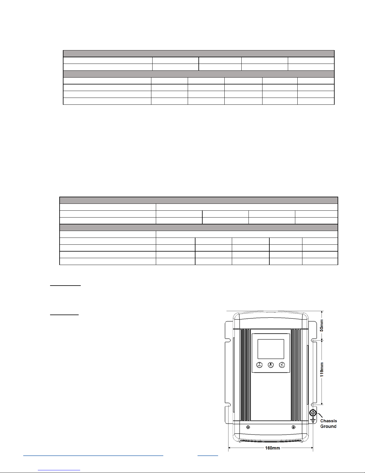
Mounting the Charger:
Choose an appropriate mounting location.
For installing in an indoor location, the unit should be
mounted vertically (with the battery terminals facing
downwards). This provides the best thermal
performance and drip protection. The unit should
NOT be mounted upside down.
For installing in a boat or marine environment, the
unit should only be mounted vertically (Battery
Terminals facing downwards) to provide adequate
 Loading...