

KISAE AC1260 User Manual
A
bso Charger
12V 20A (AC1220)
12V 40A (AC1240)
12V 60A (AC1260)
Owner’s Manual

For safe and optimum performance, the KISAE Abso Charger must be used properly. Carefully read and
follow all instructions and guidelines in this manual and give special attention to the CAUTION and
WARNING statements.
PLEASE KEEP THIS MANUAL FOR FUTURE REFERENCE
Disclaimer
While every precaution has been taken to ensure the accuracy of the contents of this guide, KISAE
Technology assumes no responsibility for errors or omissions. Note as well that specifications and
product functionality may change without notice.
Important
Please be sure to read and save the entire manual before using your KISAE Abso Charger. Misuse
may result in damage to the unit and/or cause harm or serious injury. Read manual in its entirety
before using the unit and save manual for future reference.
Product Numbers
AC1220
AC1240
AC1260
Abso Charger 20A
Abso Charger 40A
Abso Charger 60A
Document Part Number
MU AC1220 Rev A
Service Contact Information
Email: info@kisaetechnology.com
Phone : 1 877 897-5778
1 604 629-6067
Web : www.kisaetechnology.com
Page 2

Table of Contents
1. INTRODUCTION....................................................................................................4
2. PRODUCTDESCRIPTION ....................................................................................... 5
3. UNDERSTANDINGTHEUNIT ................................................................................. 5
4. INSTALLINGTHECHARGER....................................................................................7
5. UNITOPERATION ................................................................................................. 9
6. SPECIFICATIONS ................................................................................................. 14
7. WARRANTY........................................................................................................ 16
AppendixA1
AppendixA2
Page 3

1. INTRODUCTION
Thank you for purchasing the KISAE Abso Charger. With our state of the art, easy to use design,
this product will offer you reliable service by providing a multi-stage multi-bank battery charger to
charge different types of batteries you have installed in your boat, RV, vehicle or your cabin
battery bank.
This manual will explain how to use this unit safely and effectively. Please read and follow these
instructions and precautions carefully.
IMPORTANT SAFETY INFORMATION
This section contains important safety information for the KISAE Abso Charger. Each time,
before using the unit, READ ALL instructions and cautionary markings on or provided with the
unit, and all appropriate sections of this guide.
The KISAE Abso Charger contains no user-serviceable parts. See Warranty section for how to
handle product issues.
WARNING:
Do not cover or obstruct any air vent openings and/or install in a zero-clearance compartment.
WARNING:
SERIOUS INJURY. KEEP AWAY FROM CHILDREN!
• When working with electrical equipment or lead acid batteries, have someone nearby in case
• Study and follow all the battery manufacturer’s specific precautions when installing, using and
• Wear eye protection and gloves.
• Avoid touching your eyes while using this unit.
• Keep fresh water and soap on hand in the event battery acid comes in contact with eyes. If
• Batteries produce explosive gases. DO NOT
• Keep unit away from moist or damp areas. Never expose unit to snow, water etc.
• Avoid dropping any metal tool or object on the battery. Doing so could create a spark or short
WARNING
• DO NOT use the unit in the vicinity of flammable fumes or gases (such as propane tanks or
• AVOID covering the ventilation openings. Always operate unit in an open area.
FCC INFORMATION
This equipment has been tested and found to comply with the limits for a Class B digital device,
pursuant to part 15 of the FCC Rules. These limits are designed to provide reasonable
protection against harmful interference in a residential installation. This equipment generate,
uses and can radiate radio frequency energy and, if not installed and used in accordance with
the instructions, may cause harmful interference to radio communications. However, there is no
guarantee that interference will not occur in a particular installation. If this equipment does
cause harmful interference to radio or television reception, which can be determined by turning
the equipment off and on, the user is encouraged to try to correct the interference by one or
more of the following measures:
• Reorient or relocate the receiving antenna.
• Increase the separation between the equipment and the receiver.
• Connect the equipment into an outlet on a circuit different from that to which the receiver is
• Consult the dealer or an experienced radio/TV technician for help.
LIMITATIONS ON USE
Do not use in connection with life support systems or other medical equipment or devices.
FIRE AND/OR CHEMICAL BURN HAZARD
FAILURE TO FOLLOW THESE INSTRUCTIONS CAN RESULT IN DEATH OR
of an emergency.
servicing the battery connected to the charger.
this occurs, cleanse right away with soap and water for a minimum of 15 minutes and seek
medical attention.
system.
circuit which goes through the battery or another electrical tool that may create an explosion.
: Explosion hazard!
large engines).
connected.
smoke or have an open spark or fire near the
Page 4

2. PRODUCT DESCRIPTION
The KISAE Abso Charger includes the items list below.
• Base unit (AC1220 or AC1240 or AC1260)
• Owner’s manual (P/N: MU IC1210)
3. UNDERSTANDING THE UNIT
AC Output Wiring
Compartment
AC Input Wire Strain
Battery Temperature
Sensor Port
Typical wiring block diagram of the Battery Charger with 3 batteries bank:
AC Source:
(90-265Vac,
50Hz/60Hz)
Battery Bank_1, _2, _3:
• The charger can charge four different types of batteries (GEL, AGM, Flooded and Lithium)
and each battery bank can have its own bulk, absorption and float current setting.
• By setting the battery type to ‘Program’, the charger will act as a power supply and can
provide power to Bank_1 only. Bank_2 and Bank_3 are disabled.
Branch Breaker:
For AC Input hardwire charging systems, it is required to use a 15A branch breaker to connect
between the AC source and the charger AC input.
AC Source:
The charger accepts full universal input voltage (90-265Vac, 47-63Hz).
Digital Display Port:
Use for external display
The interface port is used for connecting an optional external display. The external display has
identical functions to the built-in display.
Use for PC interface
• A KISAE Abso Charger PC Interface Kit (sold separately) is available and is used to connect
between the port and the PC. This can be used to monitor and make changes to the charger
settings.
• Full details of the KISAE Abso Charger PC Interface Kit, it can be found on the KISAE website
www.kisaetechnology.com
Battery Temperature Sensor Port:
CAUTION
the battery temperature lower than the actual temperature. This may overcharge and damage
Relief
Branch
Breaker
: RISK OF BATTERY DAMAGE. If temperature sensor is not being used, never set
DC Output fuses
Digital Display Port
Unit GND
Battery Neg
(Common)
12V Battery Bank 1
12V Battery Bank 2
12V Battery Bank 3
Battery Pos:
(Bank 1)
Battery Pos (Bank 2)
Battery Pos (Bank 3)
Battery Pos: Bank 1
Charger
Battery Pos: Bank 2
Battery Pos: Bank 3
Battery Neg : Common
and you can also consult your dealer for more details.
Page 5
the battery.
• A KISAE Abso Charger Temperature Sensor (sold separately) is available and is used to
connect to one of the battery terminals. It measures the battery temperature and will make
small adjustments to the battery charging voltage for better battery charging performance.
• If the temperature sensor is not used, you can also manually set the charger to Low, Normal,
or High to reflect the environmental temperature for better charging effect. See more details
on Understanding the Battery Temperature Function in Section 5.
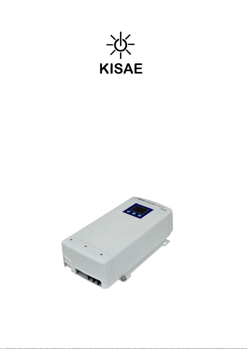
Digital Display:
• ‘Mode’ only turns on during the setting of charging stage (Mode 2 – 2 stage: Bulk and
Absorption mode only, or Mode 3 – 3-stage: Bulk, Absorption and Float charging).
• ‘Temp’ only turns on during the setting of battery temperature.
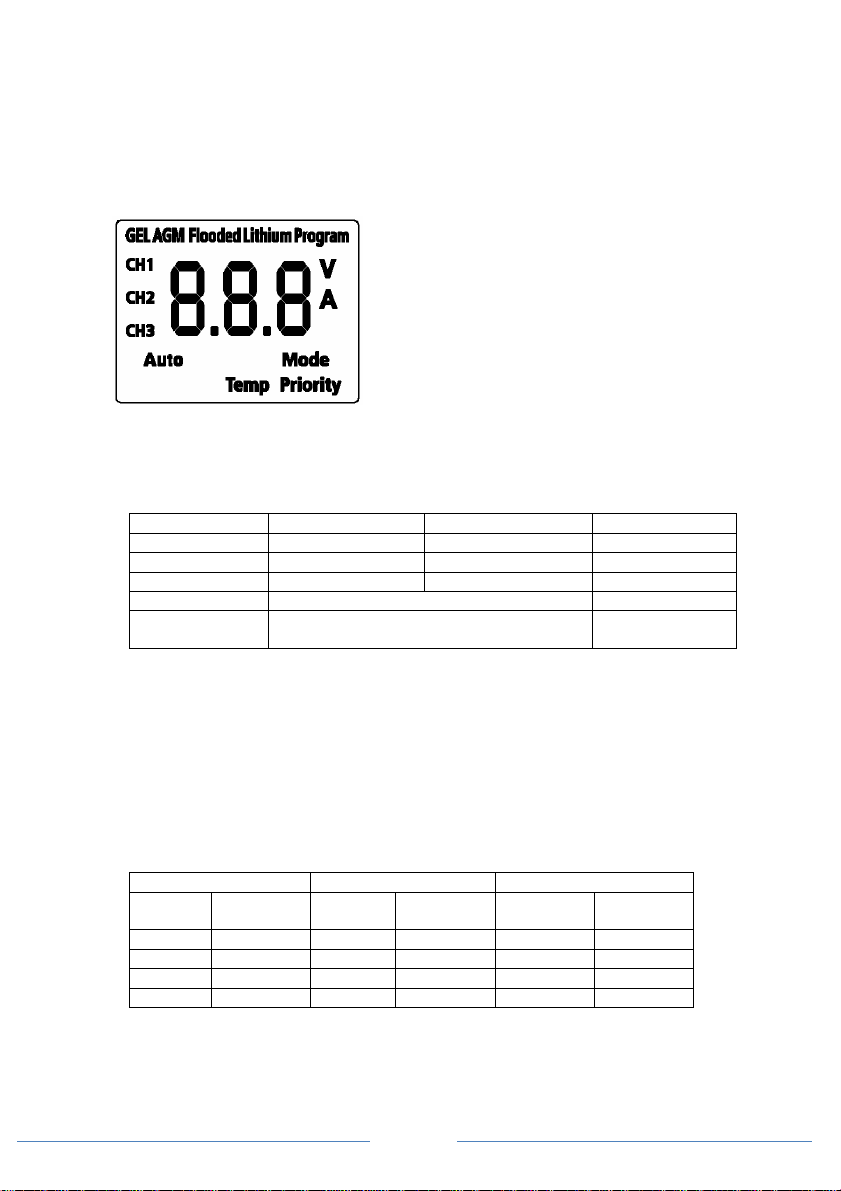
Battery Charger Voltage:
Battery Type Absorption Float Equalization
GEL 14.2 V 13.8 V N.A.
AGM 14.3 V 13.4 V N.A.
Flooded 14.4 V 13.5 V 16.0 V(See Note1)
Lithium Constant 14.2 V, 14.3 V, 14.4 V (See Note2) N.A
Program
(Power Supply)
Note 1: Equalization setting can only be used on flooded battery type selection only. See more
details on Procedure to Equalize the Flooded Battery.
Note 2: Charger will terminate charging when char ging current drop to below the set charger
termination value.
Note 3: Charger is acting as a power supply with selected constant output voltage and preset
maximum output current. With this setting, only Bank 1 can be used, Bank 2 and 2 is
Battery Bank Size Recommendation:
The battery charging current rating is based on the battery size. Each battery bank should meet
the minimum Ah rating as shown. If a smaller size battery bank is used, set the current rating to
lower value to match with the battery bank size. Normally, the minimum battery bank capacity is
based on twice the charger current rating.
disabled.
AC 1220 AC 1240 AC1260
Current
Setting
5A Min 10Ah 5A Min 10Ah 5A Min 10Ah
10A Min 20Ah 10A Min 20Ah 20A Min 40Ah
15A Min 30Ah 20A Min 40Ah 40A Min 80Ah
20A Min 40Ah 40A Min 80Ah 60A Min 120Ah
Constant 13.3 V, 13.5 V, 13.7 V (See Note3) N.A
Battery
Capacity
• ‘CH1’, ‘CH2’ and ‘CH3’ represent Battery Bank 1, 2 and 3
respectively. With individual icon turned ON, the
numerical value on the display shows individual battery
information like battery voltage in ‘V’ or charging current in
‘A’.
• ‘GEL’, ‘AGM’, ‘Flooded’, ‘Lithium’ and ‘Program’
represent different battery types setting.
• ‘Auto’ indicates silent mode is activated.
• ‘Priority’ indicates priority battery bank charging is
activated
Current
Setting
Battery
Capacity
Current
Setting
Battery
Capacity
Page 6
 Loading...