


SUPV1
SIRIUS Plug and Play Vehicle Kit
For use with most newer SI RI US P lu g an d Pl ay R ad io s
Installation Guide
with the FM Extender Cable

Congratulations on the Purchase of your new SUPV1 SIRIUS
Universal Plug and Play Vehicle Kit
Your new SU PV1 SIRIUS Universal Plug and Play Vehicle Kit lets you en joy SIRIUS® Satellite
Radio’s dig ital entertainment in any vehicle. Use this manual as a gu ide for the insta llation.
The SUPV1 S IRIUS Universal Plug and Play Vehicle Kit will work with t he Sportster™ 4 a nd
most new SI RIUS plug and play satellite radios. See your Plug and Pla y user manual for
specific pr oduct compatibility.
For the lat est information about this and other SIRIUS products and a ccessories, visit
http://www. sirius.com.

Table of Contents
TABLE OF CONTENTS . . . . . . . . . . . . . . . . . . . . . . . . . . . . . . 3
WARNING AND SAFETY INFORMATION . . . . . . . . . . . . . . . . . . . . . . 4
Safety Precautions . . . . . . . . . . . . . . . . . . . . . . . . . . . . . . . .4
Warnings . . . . . . . . . . . . . . . . . . . . . . . . . . . . . . . . . . . 5
COPYRIGHTS & TRADEMARKS . . . . . . . . . . . . . . . . . . . . . . . . . 6
PACKAGE CONTENTS . . . . . . . . . . . . . . . . . . . . . . . . . . . . . . 7
CONTROLS . . . . . . . . . . . . . . . . . . . . . . . . . . . . . . . . . . 9
INSTALLATION . . . . . . . . . . . . . . . . . . . . . . . . . . . . . . . . 10
Installing the Vehicle Dock . . . . . . . . . . . . . . . . . . . . . . . . . . . 10
Installing the Antenna . . . . . . . . . . . . . . . . . . . . . . . . . . . . . 16
Connecting the Cigarette Lighter Adapter . . . . . . . . . . . . . . . . . . . . . 19
Docking the SIRIUS Radio . . . . . . . . . . . . . . . . . . . . . . . . . . . 19
Maximizing Audio Quality From Your SIRIUS Radio . . . . . . . . . . . . . . . . . . 21
Subscribing to the SIRIUS Service . . . . . . . . . . . . . . . . . . . . . . . . 36
TROUBLESHOOTING . . . . . . . . . . . . . . . . . . . . . . . . . . . . . 37
OPTIONAL ACCESSORIES . . . . . . . . . . . . . . . . . . . . . . . . . . . 38
WARRANTY . . . . . . . . . . . . . . . . . . . . . . . . . . . . . . . . . 39
SPECIFICATIONS . . . . . . . . . . . . . . . . . . . . . . . . . . . . . . . 40
SIRIUS ID . . . . . . . . . . . . . . . . . . . . . . . . . . . . . . . . . . 41
[ Table o f Conte nt s ]
3

Warning and Safety Information
Safety Precautions
Be sure to observe the following warnings. Failure to follow these sa fety instructions and
warnings ma y result in a serious accident and/or personal injury.
Installatio n must be performed according to this installation guide. SIRIUS is not res pon-
•
sible for i ssues arising from installations not performed according t o the procedures in this
guide.
Do not oper ate the SIRIUS radio in a way that might divert your atten tion from driving
•
safely. As a driver, you alone are responsible for safely operating y our vehicle in ac cordance with traffic safety laws at all times.
Do not inst all the unit where it may obstruct your view through the w indshield, or of your
•
vehicle’s i ndicator displays.
Before atta ching the suction cup mount to your windshield, you should check your state
•
and local l aws for regulations regarding mounting this device on your windshield.
Do not inst all the unit where it may hinder the function of safety de vices such as an airbag.
•
Doing so ma y prevent the airbag from functioning properly in the even t of an accident.
To avoid sh ort circuits, do not open the unit, and never put or leave any metallic obj ects
•
(coins, too ls, etc.) inside the vehicle dock.
If the unit emits smoke or unusual odors, turn the power off immediat ely, and disconne ct
•
the unit fr om any power source.
Do not drop the unit or subject it to strong shocks.
•
The install ation and use suggestions contained in this manual are sub ject to any restr ic-
•
tions or li mitations that may be imposed by applicable law. The purch aser should check
applicable law for any restrictions or limitations before installing and/or operating this unit.
[ Warni ng a nd Sa fe ty I nform at io n ]
4

Do not inst all the FM Extender Cable where it will hinder or block yo ur view. In some
•
states it m ay be illegal to mount it on the windshield of your vehicl e. Check applicab le law
for any res trictions or limitations before installing the extender ca ble on your winds hield.
Do not inst all the FM Extender Cable where it may hinder the function of safety device s
•
such as an airbag. Doing so may prevent the airbag from functioning p roperly in the ev ent
of an accid ent.
Warnings
Noti ce T o Drive rs I n Calif orni a and Minne sota
State law p rohibits drivers in California and Minnesota from using su ction mounts on t heir
windshields while operating motor vehicles. Other dashboard or fricti on mounting optio ns
should be u sed. SIRIUS does not take any responsibility for any fines , penalties, or d amages
that may be incurred as a result of disregarding this notice. (See Ca lifornia Vehicle Code Section 26708( a); Minnesota Statutes 2005, Section 169.71)
Oper atin g Tempe ratu re
The SIRIUS Cigarette Lighter Adapter is designed to operate between - 20° to +85° C (-4 ° to
+185° F). A void leaving it in a vehicle or elsewhere where the temper ature may fall ou tside
this range.
Clea ning and Ma inte nance
If the vehi cle dock becomes dirty, turn the power off and wipe it cle an with a soft cl oth. Do
not use har d cloths, strong cleaning fluids, paint thinner, alcohol, or other volatile solvents to
clean. Thes e may cause damage to the unit.
Ciga rett e Light er A dapter
The SUPV1 c annot be powered directly from a vehicle’s 12 VDC power sy stem. It must be
powered usi ng the included Cigarette Lighter Adapter only. Connecting the SUPV1 direct ly to
the vehicle ’s 12 VDC power system may result in damage to the vehicle dock or SIRIUS r adio,
or both.
[ Warni ng a nd Sa fe ty I nform at io n ]
5

Copyrights & Trademarks
© 2006 SIRI US Satellite Radio Inc. All Rights Reserved.
® “SIRIUS”, the SIRIUS dog logo, channel names and logos are trademar ks of Sirius Sate llite
Radio Inc. All Rights Reserved.
“Sportster ” is a trademark of Sirius Satellite Radio Inc.
™
Hardware, s ubscription, and activation fee required. For full Terms & Conditions, visi t
http://siri us.com. Prices and programming are subjec t to change. Not available in HI a nd AK.
Equipment a nd subscription sold separately. Installation required wit h some equipment.
[ Copyr ig ht s & T ra de ma rks ]
6
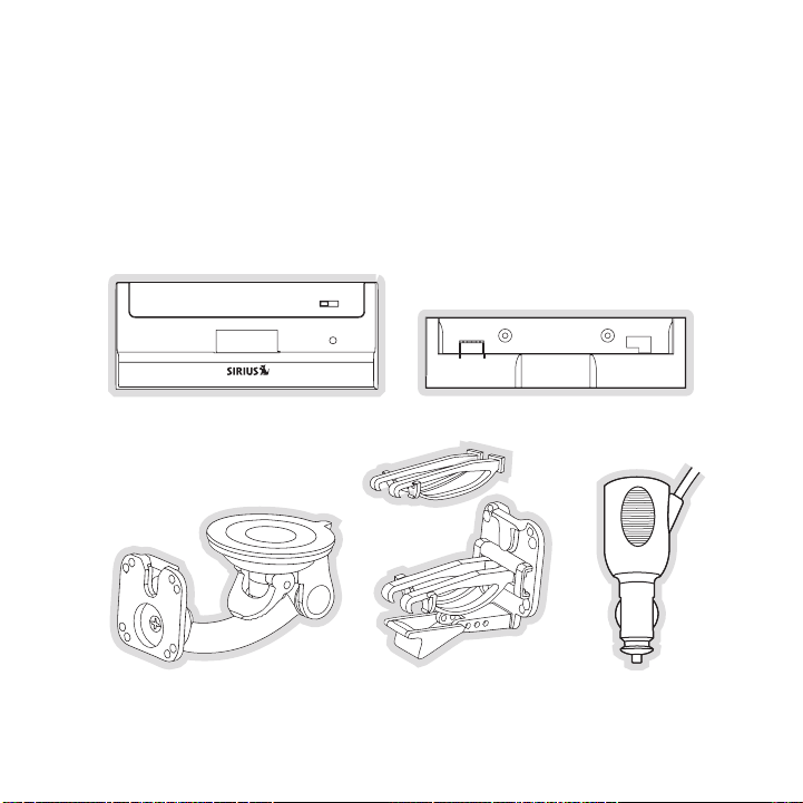
Package Contents
The followi ng items are included with your purchase of the SUPV1 SIRI US Universal Plug and
Play Vehicl e Kit. Unpack the kit carefully and make sure that everyth ing shown is pres ent. If
anything is missing or damaged, or if the kit fails to operate proper ly, notify your d ealer immediately. It is recommended that you retain the original carton and packing materials in case
you need to ship your kit in the future.
Vehic le Do ckVehic le Do ck
Sucti on Cu p Mou ntSucti on Cu p Mou nt
Vehic le Do ck Ad apterVehic le Do ck Ad apter
Vent Mount &
Vent Mount &
Exten ded V ent H ooks
Exten ded V ent H ooks
Cigar ette Light er Ad apterCigar ette Light er Ad apter
[ Packa ge C onten ts ]
7

Magne tic A ntenn aMagne tic A ntenn a
Anten na
Anten na
Cover /Tail
Cover /Tail
Mount ing
Mount ing
Screw s
Screw s
Alcoh ol Sw abAlcoh ol Sw ab
[ Packa ge C onten ts ]
8
Sucti on Cu ps (2 )Sucti on Cu ps (2 )FM Ex tende r Cab leFM Exte nder Cable
Self Adhes ive
Self Adhes ive
Cable Guid es (3 )
Cable Guid es (3 )

Controls
1
56
4
3
2
Figur e 1Figur e 1
Figure 1 an d the section following identify and describe the controls and connectors o f the
vehicle doc k.
Lock Switch : Locks and unlocks the SIRIUS radio in the vehicle dock.
1.
Moun ting Ho les : Mounting holes for attaching the suction cup mount or the vent mount.
2.
FM O UT Conn ect or: FM output for use with the optional FM Direct Adapt er.
3.
AUDI O OUT C onn ector: Optional audio output connectio n for connecting to your
4.
vehicle’s a udio system if you are not using the FM transmitter.
DC5V Power Con nector: Power connection for the cigar ette lighter adap ter.
5.
ANT Antenna Co nnector : Connection for the provided m agnetic antenna.
6.
[ Contr ol s ]
9

Installation
SIRIUS sugg ests professional installation of this product in your veh icle. Professiona l installation prov ides an experienced technician to install this product in your vehicle, adv ice for selecting a s uitable mounting location, installation of the antenna, an d routing all the necessary
wires and c ables. If the FM reception within your vehicle proves to b e poor, an instal ler will
have the ne cessary accessories to install an optional FM Direct Adapt er, or an audio c able, to
connect the audio output of the vehicle dock directly to your vehicle ’s audio system. Ask your
SIRIUS reta iler if they provide professional installation services, o r can recommend a professional inst allation service.
Installing the Vehicle Dock
When instal ling the vehicle dock in your vehicle, choose a location i n your vehicle wh ere it
will not bl ock your vision, interfere with the vehicle controls, or o bstruct the air b ag. The location should be easily accessible and provide good visibility of the d isplay, and shoul d not be
located whe re it will be in direct sunlight which will affect the vis ibility of the di splay screen.
The mountin g accessories necessary to install the vehicle dock in a v ehicle are provid ed.
Figure 1 sh ows two examples of the SIRIUS radio mounted in a vehicle: A is the suction cup
mount metho d, and B is the vent mount method using the vent mount cli p.
10
[ Insta ll at ion ]

A.
B.
Figur e 1Figur e 1
Depending u pon the mounting location you select in your vehicle, the mount should be a ttached to t he vehicle dock and installed as described in the followin g sections.
[ Insta ll at ion ]
11
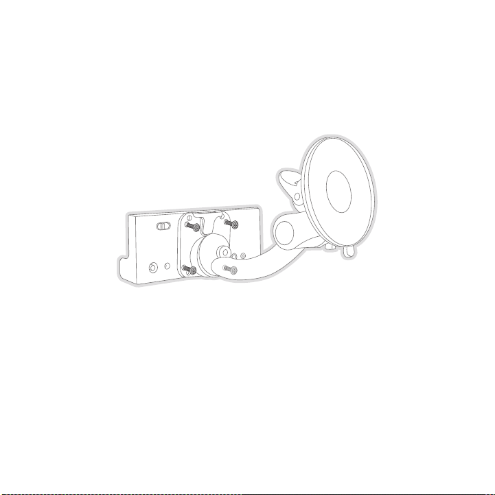
Suct ion Cup Mou nt M ethod ( A)
Figur e 2Figur e 2
The suction cup mount may be attached to any smooth surface. Before a ttaching the suct ion
cup mount t o your windshield, you should check your state and local l aws for regulatio ns
regarding m ounting this device on your windshield.
To mount th e vehicle dock using the suction cup mount, assemble the m ount as follows:
Attach the vehicle dock to the suction cup mount using the provided screws. (Figure 2)
1.
Clean the a rea where you are attaching the suction cup with an alcoho l wipe.
2.
12
[ Insta ll at ion ]

Be sure the cam lever is up (as shown in Figure 3) and position the s uction cup mount
Figur e 3Figur e 3
3.
on the wind shield or other location you which have chosen. Press the cam lever all the
way down to wards the base of the mount until it locks to adhere the s uction cup. (To
unlock the suction cup, lift the lever up.)
[ Insta ll at ion ]
13

Vent Mou nt Meth od ( B)
Slide Short
Vent Hooks Out
Remove
End Cap
Slide Extended
Vent Hooks In
Replace
End Cap
Figur e 4Figur e 4
Figur e 5Figur e 5
To mount th e vehicle dock using the vent mount method, install the ve nt mount as follo ws:
If the vent louvers in your vehicle are recessed, you may need to use the longer vent
1.
hooks with the vent mount. Refer to Figure 4 and install the longer v ent hooks into th e
vent mount. Be sure to observe the orientation of the vent hooks as s hown.
Attach the vent mount to the vehicle dock using the provided screws. (Figure 5)
2.
14
[ Insta ll at ion ]

Refer to Fi gure 6 and attach the vent mount to a heating/air conditio ning vent in your
C
B
A
D
PUSH
HOOKED
Figur e 6Figur e 6
Figur e 7Figur e 7
3.
vehicle. Po sition the two tension springs A against a vent louver B. Then push the ven t
mount into the vent, far enough so that the hooks C drop down and hoo k the rear of the
vent louver (Figure 7). Once you are sure that the hooks have grasped a vent louver, t he
tension spr ings A will keep the vent mount hooked to the louver.
[ Insta ll at ion ]
15

The angle o f the vehicle dock may be changed by changing the position of foot D on the
A
DJUSTMENT HOLES
Figur e 8Figur e 8
4.
vent mount (Figure 6) to a different adjustment hole. (Figure 8)
Installing the Antenna
The optimum mounting location for the magnetic antenna is on the roof of the vehicle, with a
minimum uno bstructed area of 12 inches by 12 inches, and exactly 6½ i nches from the re ar
roof edge o f the vehicle (the length of the rubber antenna cable cove r/tail). It is im portant to
avoid any o bstructions that will block the SIRIUS signal, obstruction s such as a roof rack,
a sunroof, roof mounted cargo containers, or other antennas. For conv ertible vehicles, the
antenna sho uld be installed on the trunk lid.
For best pe rformance, it is recommended that the antenna be installed with the rubber
antenna cab le cover/tail. This rubber antenna cable cover/tail provid es two benefits: first, it
positions t he antenna the recommended distance from the rear window, rear door/hatch, or
trunk edge to give the antenna the best view of the sky. Secondly, it conceals and pro tects
the exposed antenna cable. The rubber antenna cable cover/tail has ad hesive strips tha t hold
it securely in place.
The followi ng illustrations show the recommended mounting locations o f the antenna for
several typ es of vehicles. (Figure 9) Follow these recommendations fo r best performanc e from
the antenna .
16
[ Insta ll at ion ]

Rubber Antenna
Cover/Tail
Protective
Strips
Adhesive
Strain
Relief
Cable
Figur e 9Figur e 9
Figur e 10Figur e 10
Figur e 11Figur e 11
Seda n/Coupe . Mount the antenna alon g the rear center-line o f the vehicle roof, loca ted at the
rear of the roof near the rear window.
Pick up Truc k. Mount the antenna along the rear center-line of the cab roof, located at the
rear of the roof near the rear window.
SUV/ Mini-Va n. Mount the antenna along the rear center-line of the veh icle roof, locate d at the
rear of the roof near the rear door/hatch.
Conv ertible . Mount the antenna along the center-line of the trunk lid , with the rubber antenna
cable cover /tail directed toward the rear window.
When you ha ve selected a suitable mounting location, clean the area w here the antenna and
rubber ante nna cable cover/tail will be mounted with the supplied alc ohol swab.
[ Insta ll at ion ]
17

Connect the rubber antenna cable cover/tail to the antenna cable, mak ing sure that the strain-
Figur e 12Figur e 12
relief on t he antenna sits into the rubber antenna cable cover/tail g roove. (Figure 10 ) Route
the antenna cable through the wire channel in the rubber antenna cabl e cover/tail. Do not
remove the protective strips yet.
Temporarily position the antenna and rubber antenna cable cover/tail in the selected m ounting
area and ro ute the cable from the antenna to the vehicle’s interior b y tucking it unde rneath the
rubber mold ing around rear window, as shown in Figure 11.
Route the c able from the lowest point of the rear window into the tru nk. Take advantag e of
any existin g cable channels or wiring conduits. For SUVs, mini-vans a nd 5-door vehicle s, bring
the cable i nto the vehicle under the rubber molding for the tailgate, and continue und er the
interior tr im.
From the tr unk, or rear of the vehicle, route the cable around the pa ssenger compartme nt and
to the fron t of the vehicle, to the radio. Take care not pull the cab le across sharp e dges that
could damag e it, and keep it away from areas where it might entangle feet. Coil any ex cess
antenna cab le in a location where it can be hidden.
Once the an tenna cable is routed through the vehicle, and you are sat isfied with the c able
routing, pe el the protective material from the adhesive strips and pr ess the rubber an tenna
cable cover /tail firmly into place on the vehicle. Double check that the location of t he antenna
and rubber antenna cable cover/tail are correct, and continue to pres s firmly down on rub-
18
[ Insta ll at ion ]

ber antenna cable cover/tail for another 30 seconds. (Figure 12) At r oom temperature ( 68
degrees), m aximum adhesion usually occurs within 72 hours. During thi s period, avoid c ar
washes and other contact with the antenna and rubber antenna cable co ver/tail.
Connect the antenna cable to the ANT connection at t he rear of the ve hicle dock. (Refe r to
Figure 1 on page 9 for the location of this connector.)
Connecting the Cigarette Lighter Adapter
Connect the provided cigarette lighter adapter to the D C5V connection at the rear of t he
vehicle doc k. (Refer to Figure 1 on page 9 for the location of this c onnector.)
Docking the SIRIUS Radio
If your rad io is a SIRIUS Plug and Play series ST or SV, you will nee d to install the vehicle
dock adapte r provided with the kit. Refer to Figure 13 and place the vehicle dock lock in
the unlocke d position (1). Install the adapter into the front of the vehicle dock, pos itioning it
behind the connector and against the backrest (2). Once the adapter i s installed in th e vehicle
dock, slide the lock to the locked position (3). The radio may now be placed into the vehicle
dock, press ing the radio down until it is fully seated.
[ Insta ll at ion ]
19

1
2
3
Figur e 13Figur e 13
For SIRIUS radios which do not require the adapter, make sure the loc k on the vehicle dock
is set in t he unlocked position and place the SIRIUS radio into the v ehicle dock, pres sing the
radio down until it is fully seated. Slide the lock into the locked p osition. (Refer t o Figure 1 on
page 9 for the location of the lock.)
[ Insta ll at ion ]
20

Maximizing Audio Quality From Your SIRIUS Radio
90.1
There are t wo primary ways to connect your SIRIUS radio to your vehic le radio: Wireles s
Conn ection or Direct Connect ion . The following secti ons will help you obtain the best perfor-
mance. For the latest information go to http: //www.s iri us.com/ vehicle ins tallati on.
Wir el es s C ON Ne CTi ON
Your SIRIUS radio contains an FM transmitter. The FM transmitter send s the audio from your
SIRIUS radi o to your vehicle radio. (Figure 14)
Figur e 14Figur e 14
Included wi th your SIRIUS radio is an FM Extender Cable to maximize t he audio quality of
your SIRIUS radio when using a wireless audio connection. Should the wireless audio qu ality
without the FM Extender Cable be not acceptable, you can try using th e FM Extender Cab le
(or opt for a direct connection).
Wire less Audio Conn ection With out the FM Exte nder Ca ble
To tune you r vehicle’s FM radio and your SIRIUS radio to the same FM channel (Figure 1 4):
Turn off yo ur SIRIUS radio and tune through the FM channels on your v ehicle’s radio
1.
to locate a n FM channel that is not broadcasting in your area. If you use an FM channe l
that is bei ng used by a local broadcaster, it will interfere with the performance of y our
SIRIUS radi o. Once you have located an FM channel that is not broadca sting in your
area, save it as a preset on your vehicle radio. This will become you r SIRIUS preset.
Turn on you r SIRIUS radio. In the Settings or Menu i n your SIRIUS rad io, locate the FM
2.
Freq uency a djustments. Set the channel number on your SIRIUS radio to match the
SIRIUS pres et on your vehicle’s radio. Refer to your user guide for detailed instruct ions
on how to d o this.
[ Insta ll at ion ]
21

Note : The FM transmitter in your SIRIUS radio is automatic ally set to FM channel
88.1. This may not be the best channel in your area.
Tip: If you regularly travel between cities with differe nt active FM channels, you may
need to find channe ls tha t are not broadcasting in each city. Se veral SIRIUS radio
models can store multiple FM transmi t channel s, so you can easily switch to the
best FM channel for each city. Refer to your user guide for details on this feature .
You will also want to set the F M channels that are not bro adcasting in each city as
presets on your vehicle’s radio.
If you’re n ot sure which FM channels are not broadcasting in your hom e or travel citie s, you
can also go to http:/ /www.si riu s.com/f mchanne l and s earch for a sugge sted FM channel
based on yo ur zip code.
Wire less Audio Conn ection Usin g the FM Ex tend er Cabl e
The purpose of the FM Extender Cable is to maximize the audio quality of your SIRIUS r adio
when using the FM transmitter in your SIRIUS radio to transmit the au dio to your vehic le’s
FM radio. P roper placement of the FM Extender Cable inside your vehic le in close proxi mity
to the vehi cle’s own FM antenna will provide a strong FM signal for g ood reception. Th e FM
Extender Ca ble has suction cup mounts or permanent adhesive mounts fo r installing it o n your
vehicle’s w indow.
Because of the different kinds of FM antennas found in vehicles, and the varied locati ons of
the antenna in each vehicle, SIRIUS suggests profess ional installatio n of this product in your
vehicle. Pr ofessional installation provides an experienced technician to install this product in
your vehicl e, knowledge of your vehicle for locating the vehicle’s FM antenna, install ation of
this produc t, and routing the cable and connecting it to your SIRIUS radio. Ask your S IRIUS
retailer if they provide professional installation services, or can r ecommend a profes sional
installatio n service.
22
[ Insta ll at ion ]

The FM ante nnas found in vehicles are of four distinct types:
Aeri al Type Fe nder Mo unted F M
•
Ante nna: A fixed or retractable aerial
antenna loc ated on the front or rear
fender of t he vehicle.
Aeri al Type Ro of Moun ted FM An-
•
tenn a: A fi xed aerial antenna mounted
on the roof (often at the front or rear of
the roof, j ust above the window glass).
[ Insta ll at ion ]
23

On G lass Ty pe FM Ante nna: Wires on
•
the window glass of the vehicle, usually
near the to p of the window. It may be
located on the windshield glass, the rear
window glas s, or a rear side window in
some SUV an d mini-van type vehicles
(and other vehicles). It will look similar to
the rear wi ndow defroster wires found in
many vehicl es.
“Sha rk Fin” Ty pe FM A ntenna: A device
•
resembling a shark fin (or other shape)
located on the vehicle roof above the rear
window.
Before atte mpting installation, you should verify the type and locati on of the FM ante nna in
your partic ular vehicle. If you have trouble locating it, consult the manual which acc ompanied
your vehicl e, consult a dealer for your type of vehicle, or consult a professional ins taller.
[ Insta ll at ion ]
24
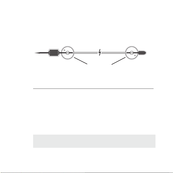
The FM Exte nder Cable should be placed inside the vehicle, as close a s possible to the
Suction Cups
vehicle’s F M antenna. A test mounting should be done first using the included suction cup
mounts to t est the installation. Once an acceptable location has been found, you will remove
the suction cups and permanently adhere the FM Extender Cable using t he adhesive mount s.
To install the FM Extender Cable in your vehicle, follow these instru ctions:
Attach the suction cups to the FM Extender Cable in the positions sho wn in Figure 15.
1.
Figur e 15Figur e 15
In this ste p, follow the specific instructions in sub-step a, b, c, o r d depending on the
2.
type of FM antenna in your vehicle:
a. Installation Instructions for Vehicles with Aerial Type Fender Mounted FM Antenna.
For vehicle s where the FM radio antenna is located on the front fende r, the FM
Extender Ca ble should be mounted vertically on the front windshield a t the edge of
the glass n earest to the antenna. (Figure 16)
For vehicle s where the FM radio antenna is located on the rear fender , the FM
Extender Ca ble should be mounted vertically on the rear window at the edge of the
glass neare st to the antenna. (Figure 17)
Attach the FM Extender Cable to the section of glass closest to the F M antenna in
a vertical orientation. (Figure 16 or Figure 17) The wire between the two suction
cups should be pulled taut and as straight as possible, and should no t obstruct the
driver’s vi ew.
Impo rtant C aution: In some states it may not be lega l to put the FM E xtender
Impo rtant C aution: In some states it may not be lega l to put the FM E xtender
Cable on th e windshield glass. In this case, the FM Extender Cable sh ould be
Cable on th e windshield glass. In this case, the FM Extender Cable sh ould be
mounted on the A-Pillar adjacent to the FM antenna. (Figure 16)
mounted on the A-Pillar adjacent to the FM antenna. (Figure 16)
[ Insta ll at ion ]
25

Alternate mounting
location on adjacent
A-Pillar
Figur e 16Figur e 16
26
[ Insta ll at ion ]
Figur e 17Figur e 17

b. Installation Instructions for Vehicles with Aerial Type Roof Mounted FM Antenna.
For vehicle s where the FM radio antenna is located on the front or re ar of the roof
of the vehi cle, the FM Extender Cable should be mounted horizontally on the front
or rear gla ss below the FM antenna, or installed into the headliner o f the vehicle
under the F M antenna.
If you are installing the FM Extender Cable on the window glass, atta ch the suc-
•
tion cups t o the glass under the FM antenna in a horizontal orientati on. The wire
between the two suction cups should be pulled taut and as straight as possible,
and should not obstruct the driver’s view. (Figure 18)
If you are installing the FM Extender Cable into the headliner, remov e the suction
•
cups and tu ck the wire into the headliner, stretched taut and straigh t, and centered under the FM antenna.
Figur e 18Figur e 18
[ Insta ll at ion ]
27

c. Installa tion In structions for Ve hicles with On Gl ass Typ e FM Anten na.
For vehicle s where the FM radio antenna is located on the window glas s, the FM
Extender Ca ble can be mounted horizontally on the glass, directly ove r the FM
radio anten na, or installed into the headliner of the vehicle directl y above the FM
antenna.
If you are installing the FM Extender Cable on the window glass, atta ch the suc-
•
tion cups t o the glass centered over the FM radio antenna in a horizo ntal orientation. The w ire between the two suction cups should be pulled taut and as straight
as possible , and should not obstruct the driver’s view. (Figures 19 & 20)
If you are installing the FM Extender Cable into the headliner, remov e the suction
•
cups and tu ck the wire into the headliner, stretched taut and straigh t, and centered above the FM antenna.
Figur e 19Figur e 19
28
[ Insta ll at ion ]

Figur e 20Figur e 20
[ Insta ll at ion ]
29

d. Insta llation In structi ons for Ve hicles with Shark Fin Ty pe FM Ante nna.
For vehicle s where the FM radio antenna is located on the rear of the roof of the
vehicle, th e FM Extender Cable should be mounted horizontally on the glass below
the FM ante nna, or installed into the headliner of the vehicle under the FM antenna.
If you are installing the FM Extender Cable on the window glass, atta ch the suc-
•
tion cups t o the glass below the FM antenna in a horizontal orientati on. (Figure
21) The wire b etween the two suction cups should be pulled taut and as s traight
as possible , and should not obstruct the driver’s view.
If you are installing the FM Extender Cable into the headliner, remov e the suction
•
cups and tu ck the wire into the headliner, stretched taut and straigh t, and centered under the FM antenna.
Figur e 21Figur e 21
30
[ Insta ll at ion ]

Plug the FM Extender Cable into the FM OUT connector of the vehicle d ock. (Figure 22)
FM OUT
From FM
Extender Cable
90.1
3.
Figur e 22Figur e 22
Tune your v ehicle’s FM radio and your SIRIUS radio to the same FM cha nnel (Figure 23):
4.
a. Turn off your SIRIUS radio a nd tune through t he FM channels on your vehicle’s
radio to lo cate an FM channel that is not broadcasting in your area. If you use
an FM chann el that is being used by a local broadcaster, it will inte rfere with the
performance of your SIRIUS radio. Once you have located an FM channel that is
not broadca sting in your area, save it as a preset on your vehicle ra dio. This will
become your SIRIUS preset.
Figur e 23Figur e 23
b. Turn on your SIRIUS radio. In the Set tings or M enu in your SIRIUS radio , locate the
FM F requenc y menu. Set the channel number on your SIRIUS radio to mat ch the
SIRIUS pres et on your vehicle’s radio. Refer to the user guide which accompanied
your SIRIUS radio for detailed instructions on how to do this.
[ Insta ll at ion ]
31

Note : The FM transmitter in your SIRIUS radio is auto matically set t o FM c hannel
Adhesive Adhesive
88.1. This may not be the best channel in your area.
Tip: If you regularly travel between cities with different active F M channels, you may
need to find c hannels that are not b roadcasting in each city. Several SIRIUS radio
models can store multiple FM transmit channels, so you can easily sw itch to the best
FM channel for each city. Refer to your user guid e for deta ils on this feature. You will
also want to se t the FM channels that are not broadcasting in each city a s presets
on your veh icle’s radio.
You should now hear the audio from your SIRIUS radio over your vehicl e’s FM radio. If
5.
the audio q uality is not satisfactory, try moving the FM Extender Cab le slightly to se e if a
better sign al can be obtained.
If you are mounting the FM Extender Cable in the headliner of the vehicle, skip this step.
6.
When you ar e satisfied with the mounting location, remove the suction cup mounts and
peel the ba cking off the adhesive mounts. Permanently adhere it in th e same position o n
the glass ( or A-Pillar), keeping it taut and as straight as possible. (Figure 24)
Figur e 24Figur e 24
Route the a ntenna cable to your SIRIUS radio. Use the included self a dhesive cable
7.
guides (if necessary) to hold the antenna wire in place until it reac hes the weather
stripping o r moulding at the edge of the window. Take advantage of an y existing cable
channels or wiring conduits and route the cable around the passenger compartment to
the vehicle dock. Take care not pull the cable across sharp edges tha t could damage it ,
and keep it away from areas where it might entangle feet. Coil and se cure any excess
antenna cab le in a location where it can be hidden and secured.
Plug the FM Extender Cable into the FM OUT connector of the vehicle d ock (Refer to
8.
Figure 22 o n page 31.)
This comple tes the installation of the FM Extender Cable. If you’re n ot sure which FM channels are no t broadcasting in your home or travel cities, you can also go to htt p://sir ius .
com/ fmchann el and search for a suggested FM channel based on your zip code.
[ Insta ll at ion ]
32

FM
TRANSMITTER
OFF
FM
TRANSMITTER
OFF
Figur e 25Figur e 25
Figur e 26Figur e 26
Dir eC T CON Ne CT iON s
Direct conn ection provides better audio performance than a wireless c onnection and rem oves
the possibi lity of interference from local FM broadcasters.
Dire ct W ired Au dio Connect ion
If your veh icle radio offers an “AUX IN” or “LINE IN” connection, it is the best audio connection availa ble. If the “AUX IN” or “LINE IN” connector is located on the front of your vehicle
radio, this is also the easiest connection. (Figure 25)
Purchase an audio cable that matches the connection type of your vehi cle radio and you r
1.
SIRIUS radi o at your local electronics retailer. Your SIRIUS radio re quires a 1/8” ste reo
male connec tor. Your local electronics retailer can help you determin e the proper connection for your car radio.
Plug one en d of the cable into the “AUDIO OUT” or “LINE OUT” jack on your SIRIUS
2.
radio. Plug the other end into your “AUX IN” or “LINE IN” jack on you r vehicle radio.
Note : Refer to your vehicle radio manufacturer’s guidelines for corre ct installation.
Note : If th e “AUX IN” or “LINE IN” connection is on the back of your vehicle radio, yo u may
want to con sider professional installation. (Figure 26)
[ Insta ll at ion ]
33

Cass ette Adapte r
FM
TRANSMITTER
OFF
Figur e 27Figur e 27
If your veh icle radio has a cassette player:
Purchase a Cassette Adapter at your local electronics retailer.
1.
Connect the adapter between the “AUDIO OUT” or “LINE OUT” on your SIR IUS radio
2.
and the veh icle radio’s cassette slot. (Figure 27)
Note : Refer to the cassette adapter manufacturer’s guidelines for cor rect use.
34
[ Insta ll at ion ]

SIRI US F M Direc t Ad apter
FM
DIRECT
ADAPTER
90.1
Vehicle FM
Antenna
Figur e 28Figur e 28
If your veh icle radio does not have an “AUX IN” or “LINE IN” jack, th e SIRIUS FM Direc t
Adapter pro vides a wired connection between your SIRIUS radio and you r vehicle radio, eliminating the outside static and interference you sometimes experience w hen using a wirel ess
FM connecti on. (Figure 28)
Professiona l installation may be required. See your local SIRIUS reta iler.
For the lat est information refer to ht tp://ww w.siriu s.c om/vehi cleinst all ation. (The SI RIUS
FM Direct A dapter is available at your local SIRIUS retailer or at ht tp: //shop. sirius. com ).
[ Insta ll at ion ]
35

Subscribing to the SIRIUS Service
Before you can listen to the SIRIUS service, you need to subscribe to the SIRIUS Satel lite
Radio servi ce. To subscribe, do the following:
Be sure tha t the SIRIUS radio is correctly installed, is in the vehic le or home dock, and
1.
that the an tenna is oriented to receive the SIRIUS signal.
Turn on the radio. After the startup sequence, it will update the SIR IUS channel line- up.
2.
Wait until the channel updates have completed before pressing any but tons.
Once the ch annels have been updated, the display will change to
3.
Call 1-888- 539-SIRIUS to Sub scribe and will tune to channel 184. You will not be able
to listen t o other channels until you activate your SIRIUS subscripti on.
Use the rad io’s channel up/down buttons to tune to channel 0 to displ ay the radio’s
4.
unique 12-d igit SIRIUS ID Number (SID). (Figure 1) You can also tune to channel 0 by
using the r emote control: Press the Se lect button th en the 0 (zero) b utton and then
press the S ele ct button again. The SID number is also available on th e radio’s packaging, and ma y also be accessed by pressing the MENU b utton and selecti ng Sirius ID.
Write the S ID number down in the space provided near the end of this guide.
Have your c redit card handy and contact SIRIUS on the Internet at:
5.
h ttps:// activat e.s iriusra dio.com /
and follow the prompts to activate your subscription. You can also ca ll SIRIUS toll-fr ee
at: 1-888-5 39- SIRIUS (1-888-539-7474).
When you ha ve successfully subscribed to the SIRIUS service, and the radio has been
6.
updated wit h your subscription information, an alert will be displaye d. To continue, p ress
the Select button.
You are now ready to begin enjoying SIRIUS Satellite Radio’s digital entertainment, an d can
tune to oth er channels!
36
[ Insta ll at ion ]

Troubleshooting
Symp tom Solu tion
SIRIUS radi o does not
power on
SIRIUS radi o displays:
Ante nna Not Detected
SIRIUS radi o displays:
Acqu iring S ignal
Audio stati c or loss of
clarity
No sound The audio c ables are not connected, or the FM radio is set to
Blown fuse, or the Cigarette Lighter Adapter is not properly connected.
Check the C igarette Lighter adapter connection. Refer to the
vehicle’s o wners manual for the location of the vehicle’s fuse
panel and c heck for a blown fuse.
The satelli te antenna is not connected to the vehicle dock.
Check the s atellite antenna connection to the vehicle dock.
No satellit e signal is being received.
Check for o bstacles over or around the satellite antenna.
Change the vehicle location to eliminate nearby obstacles
(bridges, o verpasses, tress, buildings, etc).
The FM freq uency contains static.
Locate a qu iet FM frequency on your vehicle radio and set the FM
transmitter frequency of the SIRIUS radio to match.
If using th e Audio Out connector, check the cable connections.
the wrong f requency. Check the audio cables at the radio and
the radio. Verify that the FM transmitter in the radio is set to On.
Tune the FM radio to the same FM frequency to which the radio
is tuned.
[ Troub le sh ootin g ]
37

Optional Accessories
The followi ng optional accessories are available for purchase from yo ur SIRIUS retaile r to
maximize yo ur SIRIUS experience:
SUBX 1 SI RIUS Pl ug a nd Play Uni versal Boom box
The SUBX1 S IRIUS Plug and Play Universal Boombox is a portable dockin g station and aud io
system for use with the SIRIUS radio. With the built-in amplifier and speakers, the bo ombox
delivers ri ch, powerful sound indoors or outdoors, and features an au xiliary input for other
audio devic es.
Included wi th the boombox is an adjustable indoor/outdoor windowsill antenna with 20’ of
cable and a n AC adapter.
SUPH 1 SI RIUS Un iver sal Plu g an d Play Home Kit
The SUPH1 S IRIUS Universal Plug and Play Home Kit is a compact home d ock that position s
the radio f or easy viewing and operation. Designed for quick and easy self-installatio n, it
includes al l necessary cabling to connect your SIRIUS radio to your h ome audio system.
The kit inc ludes a compact tabletop/desktop home dock with FM output for wireless conn ectivity, an audio cable for connection to any stereo bookshelf system, an adjustable in door/outdoor window sill antenna with 20’ of cable, and an AC Adapter.
[ Optio na l Acces so ri es ]
38

Warranty
12 M onth Warran ty
SIRIUS S atellite Ra dio Inc. (t he “Company ”) w arrants to the origina l retail pu rchaser of this produc t
that sho uld this pr oduct or an y part ther eof, under norm al use and conditions, be proven defective i n
material or workman ship within 12 months from the da te o f original purchase, s uch defect( s) will be
repaired or replace d with new or recondit ione d produ ct ( at the Comp any’s optio n) without charge for
parts an d repair la bor. To obt ain repair or r eplacem ent within the terms of th is Warranty , the produ ct
is to be delivered with proof of warranty cov erage ( e.g. dated bill of sale), specificati on of defec t(s),
transpor tation prep aid, to the location s hown below unde r WARRANTY RETURN.
This War ranty does not extend to the elim inat ion of exte rnally gene rated stati c or noise, to correct ion
of anten na problems , to costs incurred fo r in stallat ion, removal or reinstalla tion of the product, o r to
damage t o tapes, co mpact discs , speakers, acc essorie s, o r vehicle e lectrical s ystems.
This War ranty does not apply t o any produ ct o r part ther eof which, in the opin ion of the Company,
has suff ered or bee n damaged t hrough alte rati on, imp rope r installat ion, mishan dling, misu se, neglect ,
accident , or by rem oval or def acement of the factory ser ial number/ bar code la bel(s). THE EXTENT
OF THE C OMPANY’S LI ABILITY UND ER THIS WAR RANT Y IS LI MITE D TO THE RE PAIR OR
REPLACEM ENT PROVIDE D ABOVE AND , IN NO EVE NT, SHALL T HE C OMPANY’S LI ABILITY
EXCEED T HE PURCHASE PRICE PAID BY PURCHAS ER F OR THE PROD UCT.
This War ranty is in lieu of al l other exp ress warran ties or liabili ties. ANY I MPLIED WARR ANTIES, INCLUDING ANY IMPLIED WARRANTY O F MERCHANTA BILI TY, SHA LL B E LIMITED T O THE DURATION OF THIS WRITTE N WARRANTY. ANY ACTION FOR BREACH OF ANY WARRANT Y HEREUNDER IN CLUDING ANY IMPLIED WA RRANTY OF M ERCH ANTABIL ITY MUST BE BRO UGHT
WITHIN A PERIOD OF 48 MONTHS F ROM DATE OF ORI GINAL P URCH ASE. IN NO CASE SHALL
THE COMP ANY BE LIAB LE FOR ANY CONSEQUENTI AL O R INCID ENTA L DAMAGES F OR
BREACH O F THIS OR A NY OTHER WA RRANTY, EXP RESS OR IMP LIED , WHATSOEVE R. No
person o r represent ative is au thorized to ass ume for the Company an y liability other than expressed
herein i n connectio n with the sale of thi s pr oduct. Some states do not allow l imitations on how long
an impli ed warranty lasts or t he exclusio n or limita tion of inciden tal or cons equential d amage so th e
above li mitations o r exclusion s may not a pply to you . Th is Warranty gives you specific le gal rights and
you may also have o ther rights which vary fro m state to state.
WARRANTY RETURN: To obtain rep air or repl acem ent wit hin the terms o f this Warr anty, pleas e return pro duct to an authorized retailer or cal l Custo mer Service at 1-800-869-5 187; proof of purchase
and desc ription of defect are required. P rodu cts to be r eturned to an approved warranty s tation must
be shipp ed freight prepaid.
[ Warra nt y ]
39

Specifications
Cigarette L ighter Adapter Fuse Requirement . . . . . . . . . . . . . . . . . . . . . . . . . . . . 2A Sl ow Blow
Cigarette L ighter Adapter Cable Length . . . . . . . . . . . . . . . . . . . . . . . . . . . . . . . . . . . 1.8m (6ft.)
Cigarette L ighter Adapter Operating Temperature . . . . . . . . . . -20° to +85° C (-4° to +185° F)
Vehicle Doc k Power Requirements . . . . . . . . . . . . . . . . . . . .10-16 Volts, Negative Ground, DC
Antenna Typ e . . . . . . . . . . . . . . . . . . . . . . . . . . . . . . . . . . . . . . . . . . . . . . . .Low Profile Ma gnetic
Antenna Cab le Length . . . . . . . . . . . . . . . . . . . . . . . . . . . . . . . . . . . . . . 21’ (single micro-cable)
Connector T ype . . . . . . . . . . . . . . . . . . . . . . . . . . . . . . . . . . . . . . . . . . . . . . . . SMB (right-angle)
Audio Out I nterface . . . . . . . . . . . . . . . . . . . . . . . . . . . . . . . . . . . . . . . 1/8” / 3.5 mm Stereo Jack
[ Speci fi ca tions ]
40

SIRIUS ID
Write down the SIRIUS ID (SID) of your SIRIUS radio in the space prov ided below.
SID: _______________________________________
[ SIRIU S ID ]
41


SIRI US Cust ome r Servi ce: 1-888-539-7474
customercar e@sirius-radio.com
SIRI US Sate lli te Radi o Inc.
1221 Avenue of the Americas
New York, N Y 10020
1-888-539-7 474
http://www. sirius.com

SI RIU S Sa tell ite Rad io I nc.
1221 Avenue of the Americas
New York, NY 10020
(800) 869-5590
http://sirius.com
SIRIUS SUPV1-FM Extender Cable (0 91806a)
 Loading...