

KIRLOSKAR UP 50/30B, UP 150/45, UP 65/24, UP 125/30B, UP 125/30A Instruction On Installation, Operation And Maintenance
...
INSTRUCTION ON
INSTALLTION,
OPERATION &
MAINTENANCE
FOR KIRLOSKAR PUMP
TYPE UP METRIC
KIRLOSKAR BROTHERS LIMITED
“Yamuna”S.No.98/3 to 7, Baner, Pune 411045


1.
GENERAL
2. SAFETY INSTRUCTIONS
3. INSTALLATION
4. OPERATION
CONTENTS
5. TECHNICAL DATA
6. MAINTENANCE
7. OVERHAULING
8. GENERAL OUTLINE DIMENSIONS
9. SPARE PART LIST AND CROSS-SECTIONAL DRAWINGS
10. EXPLODED VIEW.
Please ensure these instructions are read fully before installation and operation of the
pump.
Please furnish complete name plate details, part description, part nos, material construction
and quantity while ordering spare parts.

1. GENERAL
1.1 The booklet covers instructions for following types of UP (M) pumps.
UP 50/30A UP 125/24 UP 150/38BC
UP 50/30B UP 125/30A UP 150/45
UP 65/24 UP 125/30B UP 150/45 BC
UP 65/24A UP 100/35 UP 200/30
UP 80/24 UP 100/38 UP 200/38
UP 65/38 UP 125/35 UP 250/30
UP 65/38M UP 150/26N UP 250/38
UP 80/30 UP 150/30 UP 150/53A
UP 80/38 UP 150/30A(N) UP 150/53F
UP 100/24 UP 150/38A UP 200/42
UP 100/29 UP 150/38B
1.2 These are horizontal split casing type pumps with suction and discharge nozzles and
their supporting feet integrally cast in the lower half casing. This construction
enables to remove the rotating unit for inspection and repairs by just removing upper
half casing, and without disturbing alignment, pipe connection or prime mover.
1.3 Pumps when properly installed and given due care in operation and maintenance
should operate satisfactorily for a long period.
1.4 When the pump is received, sometime before the actual use of pump, it should be
inspected and located in dry place. The coupling should be rotated periodically (once
in a month) to prevent pitting of bearing surfaces.
1.5 Generally all the UP pumps mentioned above are similar in construction with minor
changes of some parts.
1.6 Pump Identification: All pumps are designated by serial number, model number, size
and type. This information is stamped on an identification plate which is fixed on the
pump.
IOM/UP_METRIC Issue Date: 31/12/2007
Page 4 of 66
Last Revision: 12/06/2012

1.7 Nomenclature of the pump
Nomenclature for pump is as given below.
UP 100/35
UP- Basic pump type
100- Nominal Delivery size in mm
/ - Always slash
35- Nominal Impeller diameter in cm.
PUMP DESCRIPTION
Casing
Impeller
Shaft
- The casing is of axially-split volute design with suction and discharge flanges and
mounting feet cast integral with the lower half casing. Tapped and plugged holes are
provided for priming, vent, drain and gauge connections. Upper half casing is
removable without disturbing suction or discharge piping.
Suction and Discharge is on a common centerline in both the horizontal and vertical
planes.
- The impeller is of the enclosed double-suction (except UP 150/56 pump),
statically and hydraulically balanced. The impeller is keyed to the shaft and
positioned axially by the shaft sleeves. Hub shall have sufficient metal thickness to
allow machining for installation of casing wear rings.
- The shaft shall be of ample size to operate under load with of minimum deflection.
Shaft Sleeves
with the pumped liquid. An O-ring shall be furnished under sleeve to prevent
- The shaft sleeves should protect the shaft from wear and from contact
leakage.
Insert (Stuffing Box)
type gland to permit removal and access to packing. Ample space is provided for
repacking the insert.
Bearings
IOM/UP_METRIC Issue Date: 31/12/2007
Page 5 of 66
- The bearings are grease lubricated or oil lubricated. The inboard or coupling
end bearing is a single row ball bearing. The outboard bearing is a double row
cylindrical roller bearing which is retained by bearing locknut and lock washer.
- The insert is consisting of at least six packing rings and a split
Last Revision: 12/06/2012

Bearing Housings
and assure positive alignment of the rotating element. The housings provides a fit for
the inboard bearing that allows freedom for thermal expansion while the outboard
bearing is clamped in place to take all thrust loads and keep the rotating element in
its proper axial location.
- The bearing housings are bolted to the end of the lower half casing
Base plate
be provided with a drip pan beneath the pump. The drip pan contains a tapped drain
connection.
Coupling
- The base plate is sufficiently rigid to support the pump and driver and shall
- Coupling can be supplied – Snap-wrap / Pin-Bush / Spacer type
Coupling Guard
Rotation
- Pump can have clockwise or counterclockwise rotation when viewed from its
driving end
- The coupling guard can be in MS / AL / Bronze.
IOM/UP_METRIC Issue Date: 31/12/2007
Page 6 of 66
Last Revision: 12/06/2012

2. SAFETY INSTRUCTIONS:
2.1: General Information
Before performing any actions detailed within this instruction, the Site Health and
Safety instructions must read and fully understood. The instructions in this
document also must be read and fully understood.
Whenever the equipment is operated, maintained or used in any way, the procedures
detailed within the Health and Safety Dossier (DHS) and any procedures detailed
within these instructions shall be followed. The pump supplied by Kirloskar Brothers
Limited (KBL) has been designed with safety in mind, where hazards cannot be
eliminated; the risk has been minimized by the use of guards and other design
features. Some hazards cannot be guarded against and the instructions below MUST
BE COMPLIED WITH for safe operation. These instructions cannot cover all
circumstances. It is the responsibility of the user of the equipment for maintaining
safe working practices at all times.
2.1.1 KBL products are designed for installation in designated areas, which are to be kept
clean and free of obstructions that may restrict safe access to the controls and
maintenance access points.
2.1.2 Pump nameplate is fitted to each unit and must not be removed. Loss of this plate
could make identification impossible. This in turn could affect safety and cause
difficulty in obtaining spare parts. Should accidental loss or damage occur, contact
KBL immediately.
2.1.3 Access to the equipment should be restricted to the personnel responsible for
installation, operation and maintenance and they must be trained, adequately
qualified and supplied with the appropriate tools for their respective tasks.
2.1.4 KBL firmly insists that all personnel responsible for installation, operation and
maintenance of the equipment must read safety instructions mentioned in the
manual before any work is done.
IOM/UP_METRIC Issue Date: 31/12/2007
Page 7 of 66
Last Revision: 12/06/2012
2.1.5 Ear defenders should be worn where the specified equipment noise level exceeds
locally defined safe levels. Safety glasses or goggles should be worn where working
with pressurized systems and hazardous substances. Other personal protection
equipment must be worn where local rules apply.
2.2 DO NOT wear loose or frayed clothing or jewellery, which could catch on the
controls or becomes trapped in the equipment.
2.3 Operation of the equipment for the application other than for which it is supplied can
increase the risk from hazards. Please consult KBL before making such change in
the application of the equipment.
2.4 Improper installation, operation and maintenance of the product supplied by KBL
could result in injury or death.
2.5 Within the manual, safety instructions are marked with safety symbols.
Hazard
This symbol refers to general mechanical aspects of safety.
Hazard
This symbol refers to electrical safety.
2.6: Transport handling and storage instructions:
2.6.1: Transport
Pumps are dispatched in duly assembled condition. Pumps are protected against
corrosion and packed for transport by normal road, rail and sea carriers.
2.6.2: Handling
Crushing hazard
When lifting the pump or pump set, use lifting equipment having a safe working load
rating suitable for the weight specified. Use suitable slings for lifting any pump not
provided with lifting points.
IOM/UP_METRIC Issue Date: 31/12/2007
Page 8 of 66
Last Revision: 12/06/2012
The use of suitable forklift truck and four chain crane sling equipment is
recommended but locally approved equipment rating may be used.
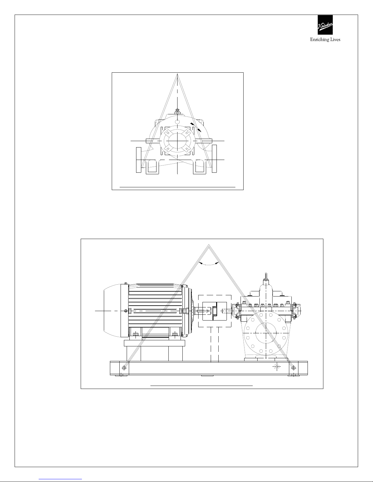
Pump should be slung as shown.
PU M P L IFT IN G A R R A N G EM ENT
Pump set must be lifted from the lifting holes provided on the pump by using
suitable four chain lifting equipment.
90°
Max.
IOM/UP_METRIC Issue Date: 31/12/2007
Page 9 of 66
PUMP SET LIFTING ARRANGEMENT
Last Revision: 12/06/2012

2.6.3: Storage.
2.6.3.1: Temporary storage for up to six weeks.
If the pump unit is not be used immediately it should be stored carefully in a
horizontal position, in a sheltered, dry location. Additional rust preventive should be
applied to all unpainted carbon steel or cast iron parts, and should not be removed
until final installation.
2.6.3.2: Long Term Storage.
If the pump is not to be installed and operated soon after arrival, store it in a
clean, dry place, having slow, moderate changes in ambient temperature. Step
should be taken to protect the pump from moisture, dust, dirt, and foreign bodies. It
is recommended that the following procedure is taken:-
a) Ensure that the bearings are packed with the recommended grease, to prevent
moisture from entering around the shaft.
b) Remove the glands, packings and lantern rings from the stuffing box if the pump
is equipped in this manner. If the pump is equipped with mechanical seal, dismantle
and coat the seal with light oil.
c) Ensure that suction and discharge branches of the pump and all other openings
are covered with cardboard, wood or masking tape to prevent foreign objects
entering the pump.
d) If the pump is to be stored where there is no protective covering, it is advisable to
cover the unit with a tarpaulin or other suitable covering.
e) The shaft should be manually rotated periodically to prevent pitting of the bearing
surfaces by moisture.
Shearing Hazard.
Do NOT place fingers or hands etc. into the suction or discharge pipe outlets and do
NOT touch the impeller, if rotated this may cause severe injury. To prevent ingress
of any objects, retain the protection covers or packaging in place until removal is
IOM/UP_METRIC Issue Date: 31/12/2007
Page 10 of 66
Last Revision: 12/06/2012

necessary for installation. If the packaging or suction and discharge covers are
removed for inspection purposes, replace afterwards to protect the pump and
maintain the safety.
Fill the bearing housing with recommended grease to ensure that the shaft and
bearings remain rust free.
2.6.3.3: Exposed or Extreme Conditions Storage.
For exposed storage or extreme variants in atmospheric or environmental conditions,
please refer to KBL for special storage instructions to suit the conditions acceptable.
3 INSTALLATIONS
3.1 Receiving pump
Upon receipt of the pump, a visual check should be made to determine if any
damage occurred during transit or handling. The main items to look for are:-
a) Broken or cracked equipment, including base, motor or pump feet and flanges.
b) Bent shaft
c) Broken motor end bells, bent eyebolts or damaged boxes of motor
d) Missing parts.
e) Pump shaft rotates freely.
Parts or accessories are some times wrapped individually or fastened to the
equipment. If any damage or losses have been incurred; promptly notify your KBL
representative, KBL Dealer and the transport company who delivered the pump.
When unloading pump units, lift equally at four or more points from the base. DO
NOTLIFT ONLY THE DRIVER OR PUMP.
IOM/UP_METRIC Issue Date: 31/12/2007
Page 11 of 66
Last Revision: 12/06/2012

3.2 Preparation
Before installing the pump, clean the suction and discharge flanges thoroughly.
Remove the protective coating from the pump shaft.
If the pump has been in storage and prepared for storage in the manner outlined
previously, remove all the grease from the bearings. The bearings should then be
flushed with carbon tetrachloride or kerosene and relubricated.
3.3 Location
The pump should be installed as near the suction supply as possible, with the
shortest and most direct suction pipe practical. The total dynamic suction lift (static lift
plus friction losses in suction line) should not exceed the limits for which the pump was
sold.
The pump must be primed before starting. Whenever possible, the pump should be
located below the fluid level to facilitate priming and assure a steady flow of liquid. This
condition provides a positive suction head on the pump. It is also possible to prime the
pump by pressurizing the suction vessel.
Pumps must be fully primed at all times during operation.
When installing the pump, consider its location in relation to the system to assure that
sufficient Net Positive Suction Head (NPSHA) is available at the pump inlet connection.
Available NPSH must always equal or exceed the required NPSH (NPSHR) of the pump.
The pump should be installed with sufficient accessibility for inspection and
maintenance. A clear space with ample head room should be allowed for the use of an
overhead crane or hoist sufficiently strong to lift the unit.
NOTE: Allow sufficient space to be able to dismantle pump without disturbing the
pump inlet and discharge piping.
IOM/UP_METRIC Issue Date: 31/12/2007
Page 12 of 66
Last Revision: 12/06/2012

Select a dry place above the floor level wherever possible. Take care to prevent
pump from freezing during cold weather when not in operation. If the possibility of
freezing exists during a shut-down period, the pump should be completely drained, and
all passages and pockets where liquid might collect should be blown out with
compressed air.
Make sure there is a suitable power source available for the pump driver. If motor
driven, the electrical characteristics of the power source should be identical to those
shown on motor data plate.
3.4 Foundation
The foundation should be strong enough to reduce vibrations and rigid enough to avoid
any twisting or misalignment.
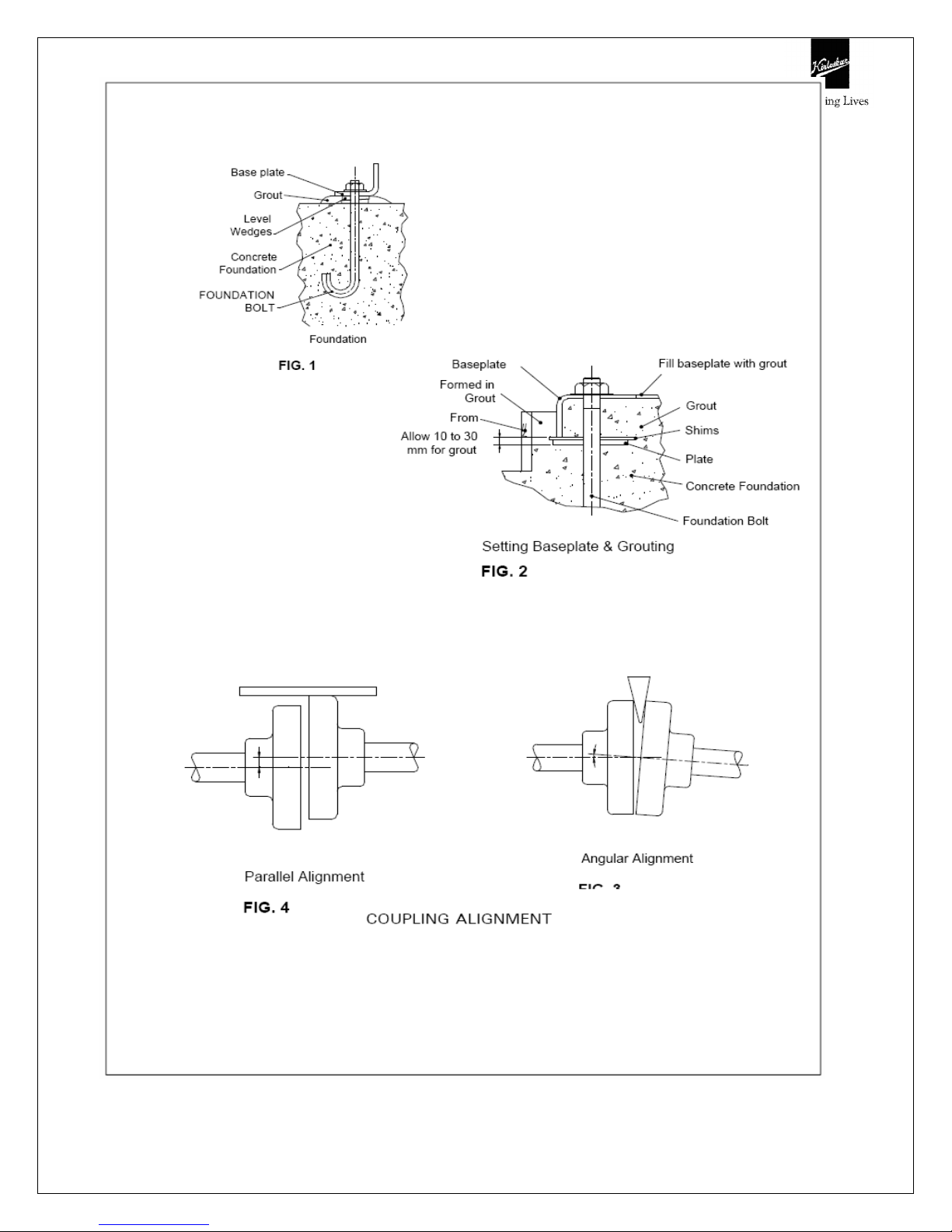
The foundation should be poured without interruptions to within 20 to 40 mm of the
finished height. The top surface of the foundation should be well scored and glued
before the concrete sets. This provides a bonding surface for the grout. Foundation
bolts should be set in concrete as shown in Fig. 1. Allow enough bolt length for
grout,shims, lower base plate flange, nuts and washers. The foundation should be
allowed to cure for several days before the base plate is shimmed and grouted.
3.5 Baseplate setting
Use blocks and shims under base for support at foundation bolts and midway
between bolts, to position base approximately 25 mm above the concrete
foundation with studs extending through hole in the baseplate.
By adding or removing shims under the base, level the pump shaft and flanges. The
baseplate does not have to be leveled. Draw foundation bolt nuts tight against
baseplate and observe pump and motor shafts or coupling hubs for alignment.
Check to make sure the piping can be aligned to pump flanges without placing pipe
strain on either flange.
IOM/UP_METRIC Issue Date: 31/12/2007
Page 13 of 66
Last Revision: 12/06/2012

Grout baseplate in completely and allow grout to dry thoroughly before attaching
piping to pump (24 hours is sufficient time with approved grouting procedure).
3.6 Grouting procedure
Grout compensates for uneven foundation, distributes weight of unit and prevents
shifting. Use an approved, non-shrinking grout as follows, after setting and leveling
unit See Fig. 2.
a) Build strong form around foundation to content grout.
b) Soak top of concrete foundation thoroughly, then remove surface water.
c) Baseplate should be completely filled with grout and, if necessary, drill vent holes
to remove trapped air.
d) After grout has thoroughly hardened, check the foundation bolts and tighten if
necessary.
e) Check the alignment after the foundation bolts are tightened.
f) Approximately 14 days after the grout has been poured or when the Grout has
thoroughly dried, apply an oil base paint to the exposed edges of the grout to
prevent air and moisture from coming in contact with the grout.
3.7 Alignment procedure
The pump driver, if supplied, is correctly aligned on its base plate at the factory. A
certain amount of deformation of the base plate is possible during transit and it is
therefore essential to check alignment, prior to final grouting.
A flexible coupling will only compensate for small amount of misalignment and
should not be used to compensate for excessive misalignment of the pump and
driver shafts.
Inaccurate alignment results in vibration and excessive wear on the bearings, sleeve
or shaft and wear rings.
Coupling alignment can be checked with dial gauge Indicator also. Alignment should
be performed after the base plate has been properly set and grout has dried
IOM/UP_METRIC Issue Date: 31/12/2007
Page 14 of 66
Last Revision: 12/06/2012

thoroughly according to instructions. Final alignment should be made by shimming
driver only.
Alignment should be made at operating temperatures.
After final alignment, it is necessary to dowel pump and driver feet to the baseplate.
FACTORS THAT MAY DISTURB ALIGNMENT
The unit should be periodically checked for alignment. If the unit does not stay in
line after being properly installed, the following are possible reasons:
a) Setting, Seasoning of the foundation.
b) Pipe strains, distorting or shifting of the machines.
c) Wear of the bearings.
IOM/UP_METRIC Issue Date: 31/12/2007
Page 15 of 66
Last Revision: 12/06/2012
IOM/UP_METRIC Issue Date: 31/12/2007
Page 16 of 66
Last Revision: 12/06/2012

3.8 Suction and Discharge Piping
When installing the pump piping, make sure to observe the following precautions:-
Piping should always run to the pump. Do not move pump to pipe. This could make
final alignment impossible.
Both suction and discharge piping should be supported independently and close to
pump so that no strain is transmitted to the pump when the flange bolts are
tightened.
Use pipe hangers or other supports at necessary intervals to provide support. When
expansion joints are used in the piping system, they must be installed beyond the
piping supports close to the pump.
It is advisable to increase the size of both suction and discharge pipes at the pump
connection to decrease the loss of head from friction.
Install piping as straight as possible, avoiding unnecessary bends. Where necessary,
use 45 degree or long sweep 90 degree fitting to decrease friction losses.
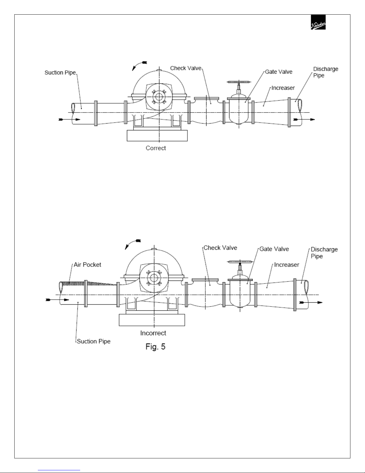
Make sure that all piping joints are air tight. Provide pipe expansions bellows when
hot fluids are to be pumped. Where reducers are used, eccentric reducers are to be
fitted in suction lines and straight taper reducers in discharge and vertical lines (See
Fig.5).
Misuse of reducers may cause the formation of air pockets in the pipe and thus
preventing the correct operation of the pump.
The suction pipe should be as short & direct as possible. Where suction lift is not
very high, it is advisable to use a foot valve. Horizontal suction line must have a
gradual rise to the pump.
The discharge pipe is usually preceded by a non-return valve or check valve and a
discharge gate valve (See Fig. 5). The check valve is to protect the pump from
excessive back pressure and reverse rotation of the unit and to prevent back flow
into the pump in case of stoppage or failure of the driver. The discharge valve is
used in priming, starting and when shutting down the pump.
IOM/UP_METRIC Issue Date: 31/12/2007
Page 17 of 66
Last Revision: 12/06/2012

4 OPERATION
4.1 Before Starting
Before initial starting of the pump, make the following inspection:
4.1.1 The unit baseplate is grouted and bolted to the foundation.
4.1.2 Alignment between pump and motor.
4.1.3 Motor is correctly wired to starting device, check voltage, phase and frequency on
motor nameplate with line circuit. Ensure correct direction of rotation prior to
coupling to pump. Check by starting motor and switching off immediately. Observe
rotation is the same as the arrow direction on the pump casing.
4.1.4 Bearing lubrication is provided (see lubrication section), also check driver lubrication.
4.1.5 Mechanical seal has been fitted or stuffing box has been packed.
4.1.6 All rotating parts are found to be free when turned by hand.
4.1.7Pump is primed. Never run the unit dry. The liquid in the pump serves as a lubricant
for close running fits within the pump and the pump may be damaged if operated
dry. The pump may be primed by using an ejector, exhauster or vacuum pump. If a
foot valve is used in the suction line, the pump may be primed by venting and filling
the casing with liquid.
4.2 Starting
4.2.1 Close valve in discharge line.
4.2.2 Open fully all valves in the suction line.
4.2.3 Turn on seal water to the stuffing box where external pipe supplied.
4.2.4 Prime the pump.
4.2.5 Start the pump driver.
4.2.6 When the pump is operating at full speed, open the discharge valve slowly.
Do not operate pump for prolonged periods with closed discharge valve, so as to avoid
overheating.
The pump should be shut down at once and the trouble corrected if the pump is running at
its rated speed and found to have any of the following defects:
a) No liquid delivered.
IOM/UP_METRIC Issue Date: 31/12/2007
Page 18 of 66
Last Revision: 12/06/2012

b) Not enough liquid delivered.
c) Not enough pressure.
d) Loss of liquid after starting.
e) Excess vibration.
f) Motor runs hot.
g) Pump bearing overheating.
4.3 Running
While the pump is running, a periodic inspection should be made of:
a) Stuffing box (soft packed pumps only). Ensure there is sufficient leakage to
lubricate the packing.
b) Bearings. Check the bearings for temperature, which should not exceed pumped
liquid temperature or 80 Deg. C whichever is the lower.
c) With mechanical seal fitted pumps, check that there is no leakage from the
stuffing box.
d) Suction and discharge gauge readings.
4.4 Stopping
a) Slowly close delivery valve and shut down driving unit in accordance with
manufacturer’s instructions.
b) Shut off external sealing liquid supply, if supplied, to relieve stuffing box pressure.
c) Successful operation of the pump depends on accurate alignment. It is
recommended to re-check the alignment after preliminary run.
IOM/UP_METRIC Issue Date: 31/12/2007
Page 19 of 66
Last Revision: 12/06/2012
IOM/UP_METRIC Issue Date: 31/12/2007
Page 20 of 66
Last Revision: 12/06/2012
 Loading...