

KIRLOSKAR NS100/26N, NS100/26Q, NS150/26QMB, NS150/26QM, NS100/26QM Instructions On Installation, Operation And Maintenance Manual
...Page 1
This is a proprietary document of Kirloskar Brothers Limited,
YAMUNA’ Survey No. 98/ 3 to 7, Baner, Pune
– 411045, India.
1
Sept
2018
Instructions on Installation,
Operation and Maintenance
Manual for Kirloskar Non-Clog
Submersible series (IE2)
1
NS IOM MANUAL
Page 2

This is a proprietary document of Kirloskar Brothers Limited,
YAMUNA’ Survey No. 98/ 3 to 7, Baner, Pune
– 411045, India.
1
Sept
2018
WARRANTY
We warrant that the pump supplied by us is free from defective
material and faulty workmanship. This warranty holds good for a
period of 12 months from the date of commissioning the equipment
or 18 months from the date of dispatch from our factory, whichever
is earlier. Our liability in respect of any complaint is limited to
replacing part/parts free of charge ex-works or repairs of the
defective part/parts only to the extent that such replacement/repairs
are attributable to or arise solely from faulty workmanship or
defective material.
This warranty holds good only for the products manufactured by us.
– KIRLOSKAR BROTHERS LIMITED –
2
NS IOM MANUAL
Page 3
This is a proprietary document of Kirloskar Brothers Limited,
YAMUNA’ Survey No. 98/ 3 to 7, Baner, Pune
– 411045, India.
1
Sept
2018
1.
2.
3.
4.
5.
6.
7.
CAUTION
DO NOT LOWER OR LIFT THE PUMP WITH THE HELP OF
CABLES.
DO NOT FILL ANY LIQUID INSIDE THE MOTOR.
DO NOT MEGGER CONTROL PANEL CONTROL CIRCUIT
TERMINALS.
DO NOT RUN THE PUMP DRY OR IN REVERSE DIRECTION.
DO NOT RUN THE PUMP WITHOUT CONTROL PANEL.
DO NOT RUN THE PUMP WITH CONTROL UNIT IN BYPASSED
CONDITION.
DO NOT MEGGER CONTROL CABLE OF THE PUMP WITHOUT
DISCONNECTING FROM THE CONTROL PANEL.
3
NS IOM MANUAL
Page 4

This is a proprietary document of Kirloskar Brothers Limited,
YAMUNA’ Survey No. 98/ 3 to 7, Baner, Pune
– 411045, India.
1
Sept
2018
INDEX
SR.
CONTENTS
NO.
1 GENERAL 4
2 SAFETY INSTRUCTIONS 7
3 INSTALLATION 8
4 OPERATION 10
5 MAINTENANCE 11
6 SHUT DOWN / STORAGE / PRESERVATION 13
7 TECHNICAL DATA 14
8 OVERHAULING 18
9 CROSS SECTIONAL DRAWING AND PARTLIST 18
PAGE
NO.
10 OUTLINE DRAWING AND DIMENSIONS SHEET 23
GENERAL ARRANGEMENT DRAWING AND DIMENSIONS
11
SHEET
12 ANNEXURE: CONTROL PANEL / PMU SPECIFICATIONS 35
13 SPARE PARTS 36
ENVIRONMENTAL ASPECT AND PRODUCT RECYCLE
14
PROGRAM
NOTE:
• Please ensure these instructions are read fully before installation and
operation of the pump.
• Please furnish complete nameplate details, name of parts, part nos. and
material of construction while ordering spare parts for the pump
28
36
4
NS IOM MANUAL
Page 5
This is a proprietary document of Kirloskar Brothers Limited,
YAMUNA’ Survey No. 98/ 3 to 7, Baner, Pune
– 411045, India.
1
Sept
2018
1. GENERAL :
* * * * *
* # * * *
* * * * * * *
* * * *
* * * *
* * * *
* * * *
* * * *
* * * *
* * * * * * *
* * * * * *
* * * * * *
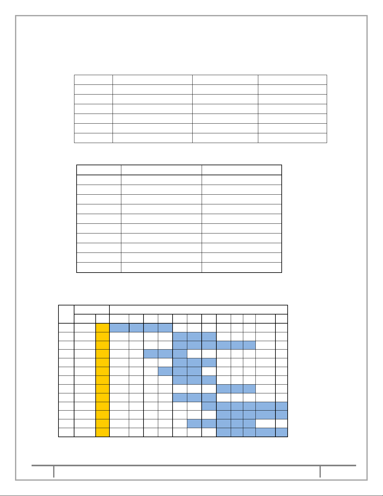
1.1 KIRLOSKAR submersible sewage pumps type “NS” is available in the following types.
1. iNS series (1HS Series Code)
Unit kW Ratings in 2Pole kW Ratings in 4Pole kW Ratings in 6Pole
iNS unit - 1 0.75-1.1 0.55-0.75 iNS unit - 2 1.5-2.2 1.1-1.5 iNS unit - 3 3.7 2.2 iNS unit - 4 5.5-7.5 3.7-7.5 2.2-5.5
iNS unit - 5 9.3-18.5 9.3-15 iNS unit - 6 22 18.5-22 -
2. NS Series (192 Series Code)
Unit kW Ratings in 4Pole kW Ratings in 6Pole
NS unit - 1 - 7.5 -11
NS unit - 2 - 15
NS unit - 3 30 18.5-22
NS unit - 4 37-45
NS unit - 5 55 37
NS unit - 6 75 45
NS unit - 7 90 55
NS unit - 8 110-132
NS unit - 9 160-200
NS unit - 10 225
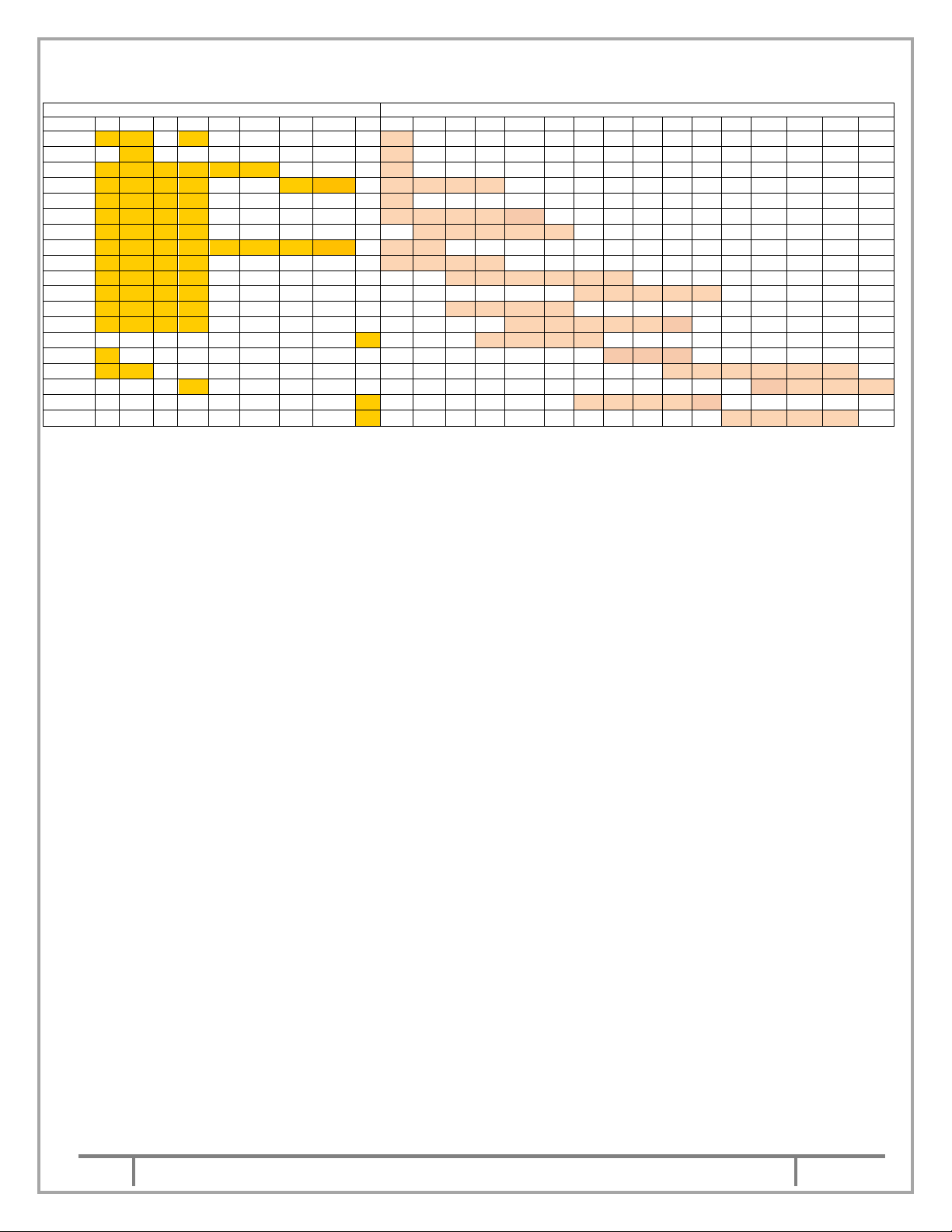
The following charts can be referred to know the pumps available in type of impellers ratings.
A. Refer below chart for 2 pole Models: (iNS)
IMPELLER kW RATING IN 2 POLE
Sr.
No.
PUMP QT 0.75 1.1 1.5 2.2 3.7 5.5 7.5 9.3 11 15 18.5 22
1 20/13
2 20/16
3 20/20
4 32/13
5 32/16
6 40/13
7 40/16
8 40/20
9 50/13
10 50/16
11 50/20
12 65/13
13 65/16
developed. #-yet to develop.
How to read – NS20/13QT 1.1/2 i (i-stands for iNS)
* * * * * *
30
75-110
132-180
-
*-design
5
NS IOM MANUAL
Page 6
This is a proprietary document of Kirloskar Brothers Limited,
YAMUNA’ Survey No. 98/ 3 to 7, Baner, Pune
– 411045, India.
1
Sept
2018
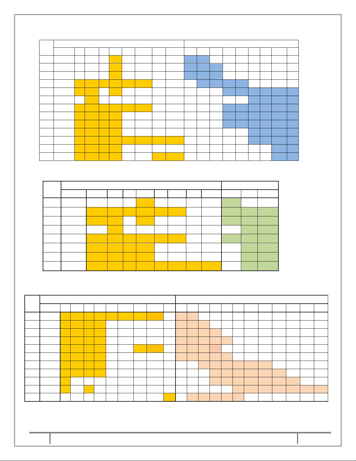
B. Refer below chart for 4 pole Models: (iNS)
* * *
* * * *
* * * *
* * * * * * * * * *
* * * * * * * * *
* * * * *
* * * * * * * * * * * *
* * * * * * * * * *
* * * * * * * * * *
* * * * * * * *
* * * * * * * * * * * *
* * * * * *
* * * * * * * *
* * * * * * * *
* *
* * * *
* * *
* * * *
* * * *
* * * *
* * * * *
* * * *
* *
* * * *
* * * *
* * * * *
* * * *
* * * * * *
* * * *
* * * * * *
*
* * * * * * *
*
*
* * * * * * *
* * * * * *
Sr.
No.
PUMP N QM Q QT NB QMB NM QMM 2.2 3.7 5.5 7.5 9.3 11 15 18.5 22
1 40/20
2 40/32
3 50/20
4 50/26
5 50/32
6 50/36
7 65/32
8 80/26
9 100/26
10 100/32
11 150/26
12 150/32
13 80/40
IMPELLER TYPE kW Rating in 4 pole
C. Refer below chart for 6 pole Models: (iNS)
Sr.
No.
PUMP N QM Q QT NB QMB NM QMM 2.2 3.7 5.5
1 40/32
2 50/26
3 50/32
4 50/36
5 65/32
6 80/26
7 100/26
8 150/26
* * * * * *
* * * * * *
* * *
* * * * * * * * *
* * * * * *
* * * * * *
* * * * * * * * * *
IMPELLER TYPE kW Rating in 6 pole
*
*
* * *
D.
Refer below chart for 4 pole Models: (NS).
Sr.
No.
PUMP N QM Q QT NB QMB NM QMM X 30 37 45 55 75 90 110 132 160 180 200 225
1
150/26
2
100/32
3
150/32
4
200/32
5
80/40
6
100/40
7
150/40
8
200/40
9
250/40
10
150/50
11
250/34
IMPELLER TYPE kW RATING IN 4 POLE
How to read – NS150/26Q 30/4
6
NS IOM MANUAL
Page 7
This is a proprietary document of Kirloskar Brothers Limited,
YAMUNA’ Survey No. 98/ 3 to 7, Baner, Pune
– 411045, India.
1
Sept
2018
E.
Refer below chart for 6 pole Models: (NS)
PUMP N QM Q QT NB QMB NM QMM X 7.5 9.3 11 15 18.5 22 30 37 45 55 75 90 110 132 160 180
50/32 * * *
50/36 *
65/32 * * * * * *
80/40 * * * * *
100/26 * * * *
100/32 * * * *
100/40 * * * *
150/26 * * * * * * *
150/32 * * * *
150/40 * * * *
150/50 * * * *
200/32 * * * *
200/40 * * * *
250/34
250/40 *
250/50 * *
300/55 *
350/40
350/47
IMPELLER TYPE
*
*
*
*
* * * *
*
* * * * *
* * * * *
*
* *
* * * *
* * * * * *
* * * * *
* * * *
* * * * * *
* * * * *
* * *
* * * * * *
* * * *
* * * * * *
* * * * *
kW RATING IN 6 POLE
1.2
The pump comprises of three units:
I.
II.
III.
Pump unit – It comprises of a delivery casing having wide volute opening and non-clog
type of impeller. The casing is attached with connector unit or stand as per order.
Stuffing box unit – It comprises double mechanical seal and mechanical seal housing
filled with oil for lubricating the seals. The seal behind the impeller is having seat ring of
silicon carbide V/s silicon carbide and second seal comprises of carbon ring V/s stainless
steel ring.
Electrical motor unit – These pumps are provided with submersible three phase squirrel
cage induction motors in watertight housing. The entire motor unit is air tested to ensure
the leak tightness of the joints. Moisture sensor is provided in the mechanical seal housing
to give the indication to control panel which in turn trips the motor, when the seal near
impeller fails. The pump is provided with high and low liquid level controllers which avoids
dry running of pump
.
1.3 The NS pump can be supplied in portable or with fixed arrangement. When the pump is supplied
with portable type, hose, connection should be provided to avoid weight of pipe line on the pump
casing. The casing is provided with stand for support. For stationary application, the pump is
mounted on the support bracket and is connected to the delivery bend through a rubber diaphragm
and connector unit. The pump slides over the guide pipes without disconnecting/disturbing the
delivery pipe line
.
1.4 NS pump is supplied with wall mounted control panel. These control panels are supplied either with
DIRECT ON LINE, STAR DELTA, SOFT STARTER or ATS type starters. These panels are
designed for smooth running of pump-set. The pump gets switched off automatically and is
protected against the following.
a. Contamination of oil with pumped liquid.
b. Dry running of pump.
c. Single phasing/reverse phasing.
d. Over load.
e. Overheating of winding [against order].
The coding of leads of the cables is clearly marked on each lead and the connections to the control
panel should be made as per connections diagram of control panel and s per below shown Figure
(1) & (2).
7
NS IOM MANUAL
Page 8

This is a proprietary document of Kirloskar Brothers Limited,
YAMUNA’ Survey No. 98/ 3 to 7, Baner, Pune
– 411045, India.
1
Sept
2018
ELECTRICAL CONNECTION DIAGRAM
( STAR DELTA STARTING )
CONTROL CABLE LEADS
M1 & M2 : FOR MOISTURE SENSOR
T1 & T2 : FOR THERMISTER
CABLES FROM PUMP
ELECTRICAL CONNECTION DIAGRAM
EARTHING
E
T2
T1
M2
M1
A1
POWER
B1
C1
B2
C2
CONTROL CABLE LEADS
M1 & M2 : FOR MOISTURE SENSOR
T1 & T2 : FOR THERMISTER
CABLE
LEADS
A2
( DOL STARTING )
CABLE FROM PUMP
M1
M2
EARTHING
E
T2
T1
A
POWER
B
CABLE
LEADS
C
Fig (1) SDS CONNECTION
Fig (2) DOL CONNECTION
1.5 As a standard scope of supply, NS pumps are supplied with 5 or 10 m long cable. This cable
consists of power cable having 4 and 3 core for Star Delta starting (for rating from 11kW to 22kW)
and 4 core cables for DOL (for rating upto 9.3kW) starting suitably designed for the voltage and
current. The control cable of 4 cores 1.5 sq.mm is used for thermistor and moisture sensor 2 wires
each.
2.
Safety Instructions:
2.1: General Information
Before performing any actions detailed within this instruction, the Site Health and Safety
instructions shall be read and fully understood. The instructions in this document shall also be read
and fully understood.
Whenever the equipment is operated, maintained or used in any way, the procedures detailed
within the Health and Safety Dossier (DHS) and any procedures detailed within these instructions
shall be followed. The pump supplied by Kirloskar Brothers Limited (KBL) has been designed with
safety in mind; where hazards cannot be eliminated, the risk has been minimized using guards and
other design features. Some hazards cannot be guarded against and the instructions below MUST
BE COMPLIED WITH for safe operation. These instructions cannot cover all circumstances. It is
the responsibility of the user of the equipment for maintaining safe working practices always. The
pumps are supplied with stickers for hazard, caution and safety wherever these are applicable.
2.1.1 Within the manual, safety instructions are marked with safety symbols.
Hazard.
a. This symbol refers to general
mechanical aspects of safety.
c.
This symbol refers to electrical
safety.
d.
b. This symbol is used to
introduce safety instructions
whose non- Observance may
lead to damage to the machine and its functions.
e.
This symbol refers to
magnetic field safety.
8
NS IOM MANUAL
Page 9
This is a proprietary document of Kirloskar Brothers Limited,
YAMUNA’ Survey No. 98/ 3 to 7, Baner, Pune
– 411045, India.
1
Sept
2018
f. This symbol refers to restrict person having heart pacemaker to avoid contact
with magnetic components while pump is in running condition or while
carrying out maintenance work of pump.
2.1.2 KBL products are designed for installation in designated areas, which are to be kept clean and free
of obstructions that may restrict safe access to the controls and maintenance access points.
Pump nameplate is fitted to each unit and must not be removed. Loss of this plate
could make identification impossible. This in turn could affect safety and cause
difficulty in obtaining spare parts. Should accidental loss or damage occur, contact
KBL immediately.
2.1.3 Access to the equipment should be restricted to the personnel responsible for installation, operation
and maintenance and they must be trained, adequately qualified and supplied with the appropriate
tools for their respective tasks.
2.1.4 KBL firmly insists that all personnel responsible for installation, operation and maintenance of the
equipment must read the manual before any work is done.
2.1.5 Ear defenders should be worn where the specified equipment noise level exceeds locally defined
safe levels. Safety glasses or goggles should be worn where working with pressurized systems
and hazardous substances. Other personal protection equipment must be worn where local rules
apply.
2.2 DO NOT wear loose or frayed clothing or jewellery, which could catch on the
controls or becomes trapped in the equipment.
2.3 Operation of the equipment for the application other than for which it is supplied can increase the
risk from hazards. Please consult KBL before making such change in the application of the
equipment.
2.4 Improper installation, operation and maintenance of the product supplied by KBL could result in
injury or death.
2.5
2.6 In case of NS pumps which are handling fluid at high temperature, the operator
should avoid touching the pump in running condition. Use safety equipments like hand gloves and
safety shoes while operating NS pumps in such applications.
3. INSTALLATION:
3.1 The NS pumps of stationary arrangement are supplied with pump connector unit and this
connector unit is connected to pump support bracket with guide shoe & rubber diaphragm
to make it leak proof joint.
9
NS IOM MANUAL
Page 10
This is a proprietary document of Kirloskar Brothers Limited,
YAMUNA’ Survey No. 98/ 3 to 7, Baner, Pune
– 411045, India.
1
Sept
2018
BOL TS
MOT OR E ND
CO VER
CAB LE
BRA CKET
STA TOR
HOU SING
STU FFIN G
BOX BUS H
CAS ING
STA ND
SUP POR T
BRA CKE T
EYE
CAB LE
CAB LE P ROT ECTIO N
TUB E
CAB LE G LAND
MOT OR E ND
COV ER
HO LDER
GUI DE
PIPE
GUI DE
PIPE
ADA PTER
RUB BER
DIAP HRA GM
GUI DE
SHO E
DUC K FO OT
BEN D
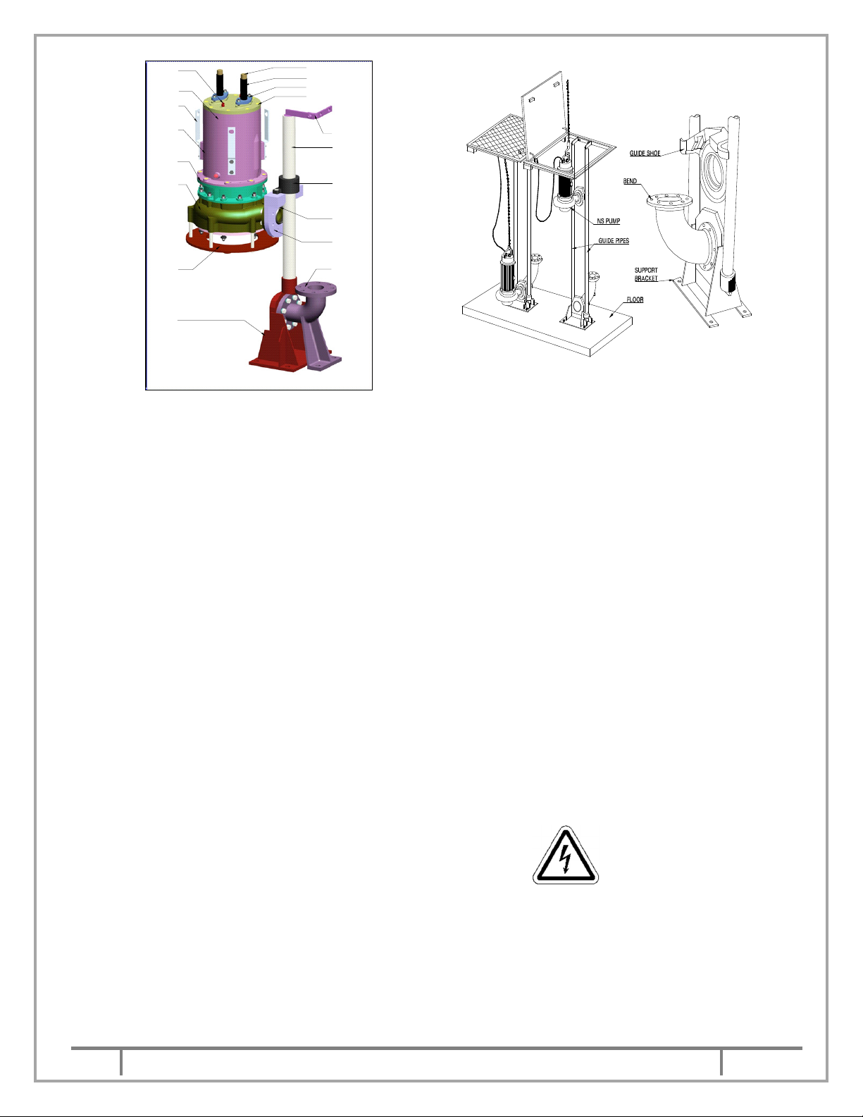
Single guide pipe arrangement (iNS) Double guide pipe arrangement
Stationary Installation view.
3.1.1 Installation of support bracket & bend –
Before installing the pump, ensure that sump bottom is flat and leveled. The support bracket &
bend should be attached and fixed to the sump bottom with foundation bolts, so that the guide pipe
shall be exactly vertical.
Ensure that support bracket and bend are located correctly relative to descending pump vertical
guide pipe and discharge pipe.
3.1.2 Lowering the pump - Attach the guide shoe & guide pipe adapter to the pump. The unsupported
length of guide pipe should not exceed 6 m.
3.1.3 Fix the guide pipe in the support bracket and locate the vertical position of guide pipe holder at the
top of the pit. Now grout the guide pipe holder.
3.1.4 Insert the above assembly in the guide pipe by dismantling the guide pipe holder & refit the holder
in the guide pipe.
3.1.5 Check- Lower the pump with the help of chain. While sliding over the guide pipe into the sump,
check that the cable is not slagging and is not under tension.
3.1.6 Ensure that the pump position is exactly vertical on the support bracket. Check by giving a jerk.
3.1.7 Before taking the pumping station into use, check that there are no loose solid pieces or other
material on bottom of sump that would damage the pump.
3.1.8 DO NOT LIFT THE PUMP WITH THE HELP OF CABLES.
3.2 The NS pumps supplied for portable installation requires no foundation. Only ensure that the
delivery pipe line is well supported and its weight is not acting on pump casing directly.
3.3 Use chain with intermediate hooks for holding to lower or lift the pump. This type of chain is specially
designed to avoid the tendency of the operator to lift the pump with the help of cable causing
damage & replacement of the cable unit. While selecting size of the chain, refer weight of the pump
given in 7.6. and chain capacity as per chart in 3.4. We recommend use of non-return valve in
delivery pipe line located before sluice valve.
10
NS IOM MANUAL
Page 11
This is a proprietary document of Kirloskar Brothers Limited,
YAMUNA’ Survey No. 98/ 3 to 7, Baner, Pune
– 411045, India.
1
Sept
2018
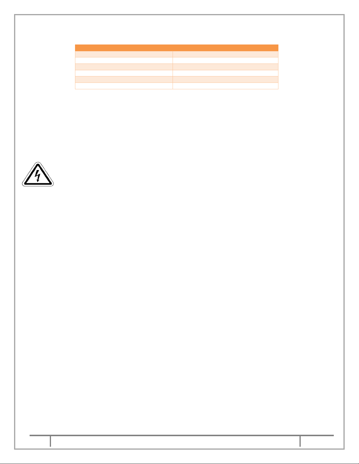
3.4 As per IS: 2429 the following sizes of chains can be used upto the weight as mentioned in the
Nom. Chain Size (mm)
Lifting capacity (Tonnes)
6
8
10
12
14
16
below chart.
0.44
0.8
1.25
1.8
2.4
3.2
4. OPERATION:
4.1 Prior to commissioning of the pump, check the following.
FILL THE OIL INSIDE THE MECHANICAL SEAL HOUSING WITH PROPER GRADE REFER CHART IN
7.5 OF CLEAN OIL FREE FROM MOISTURE. ENSURE THE MECHANICAL SEAL HOUSING OF THE
PUMP IS DULY FILLED AS PER CHART IN 7.6. CHECK THE OIL PLUG OF THE MECHANICAL SEAL
HOUSING IS INTACT.
4.1.1 Check the insulation resistance of winding by using 500 V megger. The insulation resistance of
winding should not be less than 10 mega-ohms for motor rating upto 45kW and 50 mega-ohms
beyond 45kW at phase to phase and phase to Earth. This test should be carried out at free end of
the cable. If the insulation resistance is found less than mentioned above then please consult our
service personnel.
For continuity test, connect the two wires of megger between the two ends of the same phase of
motor. It should show zero resistance. This test should be carried out for the phases.
The resistance across two moisture sensing wires M1 and M2 should be above 5 MΩ. Make sure
to remove control cable connections from terminal board [M1 and M2] before testing this. If the
resistance found less, please consult our service department. The megger test for phase to phase
and phase to Earth should be conducted serially. The megger test should show insulation
resistance above 10 MΩ for motor rating upto 45kW and 50 MΩ beyond 45kW
4.1.2 The control panel is provided with auto/manual switch. When the switch is on "Manual" position the
pumpset can be started manually by the start push button provided the liquid level is above the low
level electrode. If the switch is on "Auto" position it will start automatically if liquid level in the sump,
is above the high-level electrode. The pump set gets switched off automatically for any position of
Auto Manual switch if liquid level goes down just below the low-level electrode. This is indicated by
glowing of red lamp on control panel.
When the pumped liquid gets mixed up with the oil in the casing cover, it is indicated by glowing of
red lamp under name plate contamination. After rectification of the fault, resetting switch is to be
pressed first and then the pump set will get started by pressing "Starting switch" if it is operated on
"Manual position" or automatically if control panel is operating on "Auto position".
Before change over from star to delta connection, time delay should be sufficient to allow the motor
to attain its normal running speed. The same depends upon the load of the motor and it is generally
around 10 second.
4.1.3 LIQUID LEVEL CONTROLLERS ARE INCORPORATED IN THE PANEL TO PROTECT THE
PUMP FROM DRY RUNNING. THE LOW-LEVEL ELECTRODE SHOULD BE POSITIONED IN
SUCH A MANNER THAT LOWEST END OF ELECTRODE REMAINS ABOVE MOTOR BODY. IF
LOW LEVEL ELECTRODE IS NOT INSTALLED PROPERLY THE MOTOR BODY IS LIKELY TO
BE HEATED UP AS COOLING OF MOTOR IS DONE BY LIQUID IN THE SUMP AROUND THE
STATOR HOUSING. HENCE SUBMERGENCE UPTO FULL CORE LENGTH OF MOTOR IS
REQUIRED.
4.1.4 Before starting the pump, check the direction of rotation is as outlined below.
.
11
NS IOM MANUAL
Page 12

This is a proprietary document of Kirloskar Brothers Limited,
YAMUNA’ Survey No. 98/ 3 to 7, Baner, Pune
– 411045, India.
1
Sept
2018
4.1.5 Hoist up the pump and momentarily switch on the power. If the connections are correctly made the
pump should jerk in anticlockwise direction when viewed from top. If the pump jerks in opposite
direction, change two phases of the incoming leads to the control panel. In no case the direction of
rotation should be changed by changing the leads of motor terminals. Do not run the pump dry.
Just check in which direction the pump jerks.
4.2 While putting the pump in operation, follow the procedure outlined below.
4.2.1 Start the pump. Let the motor pick-up its full speed.
4.2.2 Open the discharge valve slowly.
4.3 Check during running that –
4.3.1 The pump is running smooth.
4.3.2 Power consumption is within limit.
4.3.3 Head and capacity developed by the pump is as specified.
4.3.4 Stop the pump immediately if any defects are detected and must not be started unless they
are rectified. Report immediately to the supplier if it is not possible to rectify the defect.
4.4 STOPPING THE PUMP:
4.4.1
Pump should be switched off only after closing the delivery sluice valve.
5. MAINTENANCE:
Preventive maintenance schedule is the periodical checks and precautions by which possibilities
of failure and break-downs are minimized.
5.1 Daily checks –
5.1.1 An hourly record of the delivery pressure and power input to the pump should be maintained.
5.1.2 Noise and vibrations is the first sign of impending troubles like bearing failure, choking of impeller
or casing and such other operating troubles. The pump performance should be checked for noise
and vibration.
5.2 Periodical checks –
5.2.1 The lubrication of mechanical seals should be checked. The lubricant might get contaminated with
foreign material or get blackened due to overheating. In such cases, oil chamber should be flushed
and filled with fresh oil. Before filling, heat the oil [Servo system 317] to 140°C. This is required to
remove moisture present in the oil.
5.2.2 THE ELECTRODES/FLOAT SWITCHES SHOULD BE CLEANED WHENEVER POSSIBLE BUT
NOT LATER THAN 15 DAYS FOR SMOOTH WORKING OF PUMP.
5.2.3 Clean the sump if there are chances of deposition of the contents of liquid handled.
5.2.4 Replace the Oil from pump periodically after 2000 hrs.
5.3 Annual checks [after one year minimum] –
5.3.1 The pump portion of the motor pump set should be overhauled completely to check the clearance
and to replace the worn-out parts. Clearance between impeller and casing ring and casing cover
are very important.
5.3.2 The effect of liquid handled on pump components should be checked. If abnormal corrosion,
erosion is observed then the components should be replaced with that of suitable material.
12
NS IOM MANUAL
Page 13

This is a proprietary document of Kirloskar Brothers Limited,
YAMUNA’ Survey No. 98/ 3 to 7, Baner, Pune
– 411045, India.
1
Sept
2018
6 SHUT DOWN / STORAGE / PRESERVATION
If operation is not required for some time after delivery, we recommend the following steps for storage
of the pump:
6.1 Storage of new pumps up to 3 months (Short storage)
i) Spray oil inside the pump housing, paying special attention to the area around the impeller
wear ring. Spray oil through inlet and outlet flanges of pump. It is then recommended to cover
the flanges with plastic caps or similar.
ii) Store the pump in an upright position in a dry place. Support all electrical cables at cable entry
points to avoid permanent distortion.
iii) Electric connecting cables are capped securely for protection purposes prior to delivery. This
protection must not be removed.
iv) Use weather-proof coverings such as flame-resistant sheeting or tarpaulins.
v) Tie coverings down to protect the pump from wind damage.
vi) Place the unit on skids, pallets or shoring higher than 5 inches from the ground for good air
circulation.
vii) Maintain an even temperature of 15 degree Celsius or higher above the dew point.
6.2 Pump long term storage requirements (Above 3 months)
Submersible units require proper preparation for storage and regular maintenance during storage.
The unit is considered in storage when it has been delivered to the job site and is awaiting
installation.
6.2.1 Storage preparation
i) Although this is a submersible pump, storage in a clean, dry area will help preserve the paint
and prevent corrosion. Hand rotation of the shaft every fifteen days is recommended to keep
the seals free and the bearings lubricated.
ii) Spray oil inside the pump housing, paying special attention to the area around the impeller
wear ring. Spray oil through inlet and outlet flanges of pump. It is then recommended to cover
the flanges with plastic caps or similar.
iii) Take care of all indoor storage requirements.
iv) Use weather-proof coverings such as flame-resistant sheeting or tarpaulins.
v) Tie coverings down to protect the pump from wind damage.
vi) Place the unit on skids, pallets or shoring higher than 5 inches from the ground for good air
circulation.
vii) Maintain an even temperature of 15 degree Celsius or higher above the dew point.
6.3 Site condition before installation of pump:
Pit in which pump is to be installed should be clean, free from hard particles such as nails, cement/
sand particles etc. Submersible pumps are designed only to handle the soft particles such as
clothes, plastic bags, etc.
6.4 Measures for prolonged shut down periods
i) The pump remains installed ready for operation when required.
ii) To maintain pump availability, the pump should be started for 10 second, once in every week.
iii) Always keep cable ends out of the sump to avoid leakage through cable ends to pump.
6.5 The pump is dismantled and stored
i) Prior to storage the pump should be checked and maintained in accordance operator must
ensure that all maintenance, inspection and repair work is carried out by qualified, authorized
staff who are familiar with the equipment and who have read the operating instructions.
ii) O-ring need to change after dismantling the pump. Do not use old O-rings for reassembly of
the pumps.
6.6 Rubber components storage ideal conditions
If the pumps are stored in below conditions, rubber components shelf life should be of 5 years
otherwise all rubber components need to be replaced after 1 year.
Condition:
a. store in cool, dry place with temperature below 15 degree Celsius.
13
NS IOM MANUAL
Page 14

This is a proprietary document of Kirloskar Brothers Limited,
YAMUNA’ Survey No. 98/ 3 to 7, Baner, Pune
– 411045, India.
1
Sept
2018
b. keep away from direct heat or open flame.
1
2
3
4
5
6
7
8
9
2
10
2
11
12
13
14
15
c. store without stretch or tension including hanging.
d. keep product wrapped or sealed to minimize the absorption of moisture.
e. store in relaxed condition free from tension, compression or other deformation.
6. TECHNICAL DATA
7.1 Non-Clog Submersible pumps are supplied at maximum speed 1450 rpm having 4 pole motors.
However, the same pump can be offered at 980 rpm having 6 pole motor if fits in duty points. The
direction of rotation is clockwise when viewed from the motor top. We have newly introduced pump
series in iNS at 2950rpm having 2Pole.
7.2 SPECIFICATIONS OF BEARINGS:
The shaft is supplied with antifriction ball bearings at both ends. The bearing specifications are
given below. The designations of bearings are as per SKF catalogue. However, equivalent bearing
in type, capacity and dimensions are also can be used.
LUBRICATION:
Bearings of NS pumps are grease sealed for life. Re-lubrication of these bearings is not required.
Sr. No. Motor rating in kW Lower bearing Qty. Upper bearing Qty.
i-NS unit - 1 6305-2RS1 1 6303 2RSH 1
i-NS unit - 2 6305-2RS1 1 6303 2RSH 1
i-NS unit - 3 6307 2RS1 1 6305 2RS1 1
i-NS unit - 4 6307 2RS1 1 6305 2RS1 1
i-NS unit - 5 6307 2RS1 1 6306 2RS1 1
i-NS unit - 6 6307-2RS1 1 6306 2RS1 1
NS unit - 1 6309-2RS1 1 6306-2RS1 1
NS unit - 2 6309-2RS1 1 6306-2RS1 1
NS unit - 3 7312 BG Back to Back
NS unit - 4 7312 BG Back to Back
NS unit - 5 7315 BG Back to Back 2 6311-2RS1 1
NS unit - 6 7318 BG Back to Back 2 6313-2RS1 1
NS unit - 7 7318 BG Back to Back 2 6313-2RS1 1
NS unit - 8 7318 BG Back to Back 2 6313-2RS1 1
NS unit - 9 7320 BG Back to Back 2 6318-2RS1 1
6309-2RS1 1
6309-2RS1 1
7.3 EBXL CABLE CURRENT CARRYING CAPACITY
Cable size (sq.mm)
8C X 1.5 20 4C X 4 + 4C X 1.5 53/22
8C X 2.5 39 4C X 10 + 4C X 1.5 96/22
4C X 25 174 4C X 16 + 4C X 1.5 133/22
4C X 35 191 4C X 25 + 4C X 1.5 174/22
4C X 50 239 4C X 35 + 4C X 1.5 191/22
3C X 4 53 4C X 50 + 4C X 1.5 239/22
3C X 10 96 4C X 70 + 4C X 1.5 295/22
3C X 16 133 4C X 120 + 4C X 1.5 414/22
3C X 25 174 4C X 95 + 4C X 1.5 355/22
3C X 35 191
3C X 50 239
3C X 70 295/22
3C X 95 355/22
3C X 120 414/22
Approx. Current carrying
capacity (amp)
Cable size (sq.mm)
Approx. Current carrying
capacity (amp)
14
NS IOM MANUAL
Page 15

This is a proprietary document of Kirloskar Brothers Limited,
YAMUNA’ Survey No. 98/ 3 to 7, Baner, Pune
– 411045, India.
1
Sept
2018
Note: These values are for reference only.
Inboard
Outboard
1
2
3
4
5
6
7
8
ELF
IOC
HPCL
CASTROL
GULF
SHELL
Model
kW
Pole Oil Qty
Pump & connector
Model
kW
Pole Oil Qty
Pump & connector
NS100/26N
7.5 4 3 Litre
240 120
NS150/26NM
15 4
3 Litre
340 155
NS100/26N
9.3 4 3 Litre
265 120
NS150/26NM
18.5 4 3 Litre
345 155
NS100/26N
11 4
3 Litre
268 120
NS150/26NM
22 4
3 Litre
355 155
NS100/26N
15 4
3 Litre
315 120
NS150/26Q
11 4
3 Litre
335 155
NS100/26N
18.5 4 3 Litre
320 120
NS150/26Q
15 4
3 Litre
340 155
NS100/
26N 22 4 3 Litre
330 120
NS150/26Q
18.5 4 3 Litre
345 155
NS100/26Q
7.5 4 3 Litre
240 120
NS150/26Q
22 4
3 Litre
355 155
NS100/26Q
9.3 4 3 Litre
307 120
NS150/26QMB
11 4
3 Litre
335 155
NS100/26Q
11 4
3 Litre
310 120
NS150/26QMB
15 4
3 Litre
340 155
NS100/26Q
15 4
3 Litre
315 120
NS150/26QMB
18.5 4 3 Litre
345 155
NS100/26Q
18.5 4 3 Litre
320 120
NS150/26QMB
22 4
3 Litre
355 155
NS100/26Q
22 4
3 Litre
330 120
NS150/26QM
11 4
3 Litre
335 155
NS100/26QM
7.5 4 3 Litre
240 120
NS150/26QM
15 4
3 L
itre 340 155
NS100/26QM
9.3 4 3 Litre
265 120
NS150/26QM
18.5 4 3 Litre
345 155
NS100/26QM
11 4
3 Litre
268 120
NS150/26QM
22 4
3 Litre
355 155
NS100/26QM
15 4
3 Litre
315 120
NS150/26QNM
11 4
3 Litre
335 155
NS100/26QM
18.5 4 3 Litre
320 120
NS150
/26QNM
15 4
3 Litre
340 155
NS100/26QM
22 4
3 Litre
330 120
NS150/26QNM
18.5 4 3 Litre
345 155
NS100/26QT
7.5 4 3 Litre
240 120
NS150/26QNM
22 4
3 Litre
355 155
NS100/26QT
9.3 4 3 Litre
307 120
NS150/26QT
11 4
3 Litre
335 155
NS100/26QT
11 4
3 Litre
310 120
NS150/26QT
15 4
3 Litre
340 155
NS100/26QT
15 4
3 Litre
315 120
NS150/26QT
18.5 4 3 Litre
345 155
NS100/26QT
18.5 4 3 Litre
320 120
NS150/26QT
22 4
3 Litre
355 155
NS100/26QT
22 4
3 Litre
330 120
NS150/32N
18.5 4 4 Litre
350 155
Consider factor of safety as 0.87 if ambient temperature is 45 degree Celcius.
7.4 MECHANICAL SEALS
:
Sr.
Motor ratings in kW Seal size in
No.
iNS all 2 Pole ratings 22
iNS 4 Pole ratings upto 7.5kW 22
iNS 4 Pole ratings above 7.5kW 40
UNIT-I & II 40
UNIT-III 55
UNIT – IV 65
UNIT – V & VI 80
UNIT – VII, VIII & IX 90
mm
SiC Vs SiC Carbon Vs St. Steel
SiC Vs SiC Carbon Vs Ceramic
SiC Vs SiC Carbon Vs St. Steel
Mechanical seal type
7.5 LUBRICATION FOR MECHANICAL SEALS:
The upper mechanical seal faces are lubricated by oil provided in casing cover. The lubricating oil
should conform to the following grades of oil available in the market.
Note: The oil used should be highly refined straight mineral product of high demulsibility free from running and acid forming
tendencies. Detergent Oil may cause foaming and should not be used.
NAME OIL SPECIFICATION NAME OIL SPECIFICATION
7.6
WEIGHTS OF PUMPS AND OIL QUANTITY:
ACANTIS HM 68 VEEDOL ATLINE 68
SERVOSYSTEM 57/68/317 PENNZOIL PENNZBELL AW 68
ENKLO 57 BPCL HYDRO 68
HYSPIN EP 68 ESSO AW68
HARMONY 68 MOBIL AW68
TELLUS 68
(approx)
15
Wt. (kg) (approx)
NS IOM MANUAL
(approx)
Wt (kg) (approx)
Page 16

This is a proprietary document of Kirloskar Brothers Limited,
YAMUNA’ Survey No. 98/ 3 to 7, Baner, Pune
– 411045, India.
1
Sept
2018
Model
kW Pole Oil Qty
(approx)
Pump & connector
Model
kW
Pole Oil Qty
Pump & connector
NS100/32N
11 4
4 Litre
330 120
NS150/32N
22 4
4 Litre
360 155
NS100/32N
15 4
4 Litre
335 120
NS150/32Q
18.5 4 4 Litre
350 155
NS1
00/32N
18.5 4 4 Litre
340 120
NS150/32Q
22 4
4 Litre
360 155
NS100/32N
22 4
4 Litre
350 120
NS150/32QM
18.5 4 4 Litre
350 155
NS100/32Q
11 4
4 Litre
330 120
NS150/32QM
22 4
4 Litre
360 155
NS100/32Q
15 4
4 Litre
335 120
NS150/32QT
18.5 4 4 Litre
350 155
NS100/32Q
18.5 4 4 Litre
340 120
NS150/32QT
22 4
4 Litre
360 155
NS100/32Q
22 4
4 Litre
350 120
NS40/20QT
2.2 4 1.7 Litre
145 55
NS100/32QM
11 4
4 Litre
330 120
NS40/20QT
3.7 4 1.7 Litre
155 55
NS100/32QM
15 4
4 Litre
335 120
NS40/20QT
1.5 4 1
.7 Litre
143 55
NS100/32QM
18.5 4 4 Litre
340 120
NS40/32QT
2.2 4 4 Litre
147 55
NS100/32QM
22 4
4 Litre
350 120
NS40/32QT
3.7 4 4 Litre
150 55
NS100/32QT
11 4
4 Litre
330 120
NS40/32QT
5.5 4 4 Litre
165 55
NS100/32QT
15 4
4 Litre
335 120
NS40/32QT
7.5 4 4 Litre
165 55
NS100/32QT
18.5 4 4 Litre
340 120
NS50/20QT
2.2 4 1.7 Litre
150 65
NS100/32QT
22 4
4 Litre
350 120
NS50/20QT
3.7 4 1.7 Litre
170 65
NS150/26NB
11 4
3 Litre
335 155
NS50/20QT
5.5 4 1.7 Litre
165 65
NS150/26NB
15 4
3 Litre
340 155 NS50/26NB
9.3 4 3 Litre
225 65
NS150/26NB
18.5 4 3 Litre
345 155
NS50/26NB
3.7 4 3 Litre
185 65
NS150/26NB
22 4
3 Litre
355 155
NS50/26NB
5.5 4 3 Litre
180 65
NS150/26N
11 4
3 Litre
335 120
NS50/26NB
7.5 4 3 Litre
180 65
NS150/26N
15 4
3 Litre
340 155
NS50/26N
9.3 4 3 Litre
225 65
NS150/26N
18.5 4 3 Litre
345 155
NS50/26N
3.7 4 3 Litre
180 65
NS150/26N
22 4
3 Litre
355 155
NS50/26N
5.5 4 3 Litre
180 65
NS150/26NM
11 4
3 Litre
335 155
NS50/26N
7.5 4 3 Litre
180 65
NS50/26Q
9.3 4 3 Litre
225 65
NS65/32Q
11 4
4 Litre
280 75
NS50/26Q
3.7 4 3 Litre
185 65
NS65/32Q
15 4
4 Litre
285 75
NS50/26Q
5.5 4 3 Litre
180 65
NS65/32Q
18.5 4 4 Litre
290 75
NS50/26Q
7.5 4 3 Litre
180 65
NS65/32Q
22 4
4 Litre
300 75
NS50/26QMB
9.3 4 3 Litre
225 65
NS6
5/32Q
7.5 4 4 Litre
230 75
NS50/26QMB
3.7 4 3 Litre
175 65
NS65/32QMB
9.3 4 4 Litre
275 75
NS50/26QMB
5.5 4 3 Litre
180 65
NS65/32QMB
11 4
4 Litre
280 75
NS50/26QMB
7.5 4 3 Litre
180 65
NS65/32QMB
15 4
4 Litre
285 75
NS50/26QM
9.3 4 3 Litre
225 65
NS65/32QMB
18.5 4 4 Litre
290 75
NS50/26QM
3.7 4 3 Litre
185 65
NS65/32QMB
22 4
4 Litre
300 75
NS50/26QM
5.5 4 3 Litre
180 65
NS65/32QMB
7.5 4 4 Litre
230 75
NS50/26QM
7.5 4 3 Litre
180 65
NS65/32QM
9.3 4 4 Litre
275 75
NS50/26QT
9.3 4 3 Litre
225 65 NS65/32QM
11 4
4 Litre
280 75
NS50/26QT
3.7 4 3 Litre
185 65
NS65/32QM
15 4
4 Litre
285 75
NS50/26QT
5.5 4 3 Litre
180 65
NS65/32QM
18.5 4 4 Litre
290 75
NS50/26QT
7.5 4 3 Litre
180 65
NS65/32QM
22 4
4 Litre
300 75
NS50/32N
9.3 4 4 Litre
275 65
NS65/32QM
7.5 4 4 Litre
230 75
NS50/32N
11 4
4 Litre
280 65
NS65/32QT
9.3 4 4 Litre
275 75
NS50/32N
15 4
4 Litre
285 65
NS65/32QT
11 4
4 Litre
280 75
NS50/32N
18.5 4 4 Litre
290 65
NS65/32QT
15 4
4 Litre
285 75
NS50/32N
22 4
4 Litre
300 65
NS65/32Q
T 18.5 4 4 Litre
290 75
NS50/32N
7.5 4 4 Litre
220 65
NS65/32QT
22 4
4 Litre
300 75
NS50/32QM
9.3 4 4 Litre
275 65
NS65/32QT
7.5 4 4 Litre
230 75
NS50/32QM
11 4
4 Litre
280 65
NS80/26N
9.3 4 3 Litre
250 85
NS50/32QM
15 4
4 Litre
285 65
NS80/26N
11 4
3 Litre
253 85
NS50/32QM
18.5 4 4 Litre
290 65
NS80/26N
15 4
3 Litre
290 85
NS50/32QM
22 4
4 Litre
300 65
NS80/26N
18.5 4 3 Litre
295 85
NS50/32QM
7.5 4 4 Litre
220 65
NS80/26N
22 4
3 Litre
305 85
NS50/32QT
9.3 4 4 Litre
275 65
NS80/26N
7.5 4 3 L
itre 220 85
NS50/32QT
11 4
4 Litre
280 65
NS80/26N
5.5 4 3 Litre
220 85
NS50/32QT
15 4
4 Litre
285 65
NS80/26Q
9.3 4 3 Litre
250 85
NS50/32QT
18.5 4 4 Litre
290 65
NS80/26Q
11 4
3 Litre
253 85
NS50/32QT
22 4
4 Litre
300 65
NS80/26Q
15 4
3 Litre
290 85
NS50/32QT
7.5 4 4 Litre
220 65
NS80/26Q
18.5 4 3 Litre
295 85
NS50/36QM
11 4
4 Litre
270 65
NS80/26Q
22 4
3 Litre
305 85
NS50/36QM
15 4
4 Litre
275 65
NS80/26Q
7.5 4 3 Litre
220 85
NS50/36QM
18.5 4 4 Litre
280 65
NS80/26Q
5.5 4 3 Litre
220 85
NS50/36QM
22 4
4 Litre
290 65
NS80/26QM
9.3 4 3 Litre
250 85
NS65/32NB
9.3 4 4 Litre
275 75
NS80/26QM
11 4
3 Litre
253 85
Wt. (kg) (approx)
(approx)
Wt (kg) (approx)
16
NS IOM MANUAL
Page 17

This is a proprietary document of Kirloskar Brothers Limited,
YAMUNA’ Survey No. 98/ 3 to 7, Baner, Pune
– 411045, India.
1
Sept
2018
Model
kW
Pole Oil Qty
(approx)
Pump & connector
Model
kW
Pole Oil Qty
Pump & connector
NS65/32NB
11 4
4 Litre
280 75
NS80/26QM
15 4
3 Litre
290 85
NS65/32NB
15 4
4 Litre
285 75
NS80/26QM
18.5 4 3 Litre
295 85
NS65/32NB
18.5 4 4 Litre
290 75
NS80/26QM
22 4
3 Litre
305 85
NS65/32NB
22 4
4 Litre
300 75
NS80/26QM
7.5 4 3
Litre 220 85
NS65/32NB
7.5 4 4 Litre
230 75
NS80/26QM
5.5 4 3 Litre
220 85
NS65/32N
9.3 4 4 Litre
275 75
NS80/26QT
9.3 4 3 Litre
250 85
NS65/32N
11 4
4 Litre
280 75
NS80/26QT
11 4
3 Litre
253 85
NS65/32N
15 4
4 Litre
285 75
NS80/26QT
15 4
3 Litre
290 85
NS65/32N
18.5 4 4 Litre
290 75
NS80/26QT
18.5 4 3 Litre
295 85
NS65/32N
22 4
4 Litre
300 75
NS80/26QT
22
4 3 Litre
305 85
NS65/32N
7.5 4 4 Litre
230 75
NS80/26QT
7.5 4 3 Litre
220 85
NS65/32Q
9.3 4 4 Litre
275 75
NS80/40NM
18.5 4 8 Litre
287 85
NS50/26QM
3.7 6 3 Litre
180 65
NS80/40NM
22
4 8 Litre
297 85
NS50/26QM
5.5 6 3 Litre
180 65
NS80/40Q
22
4 8 Litre
287 85
NS50/26QM
2.2 6 3 Litre
185 65
NS80/40Q
18.5 4 8 Litre
297 85
NS50/26QT
2.2 6 3 Litre
185 65
NS80/40QM
18.5 4 8 Litre
287 85
NS50/26QT
3.7 6 3 Litre
180 65
NS80/40QM
22
4 8 Litre
297 85
NS50/26QT
5.5 6 3 Litre
180 65
NS80/40QNM
18.5 4 8 Litre
287 85
NS50/32N
2.2 6 4 Litre
225 65
NS80/40QNM
22
4 8 Litre
297 85
NS50/32N
3.7 6 4 Litre
220 65
NS80/40QT
18.5 4 8 Litre
287 85
NS50/32N
5.5 6 4 Litre
220 65
NS80/40QT
22
4 8 Litre
297 85
NS50/32QM
2.2 6 4 Litre
225 65
NS100/26N
3.7 6 3 Litre
240 120
NS50/32QM
3.7 6 4 Litre
220 65
NS100/26N
5.5 6 3 Litre
240 120
NS50/32QM
5.5 6 4 Litre
220 65
NS100/26Q
3.7 6 3 Litre
240 120
NS50/32QT
2.2 6 4 Litre
225 65
NS100/26Q
5.5 6 3 Litre
240 120
NS50/32QT
3.7 6 4 Litre
220 65
NS100/26QM
3.7 6 3 Litre
240 120
NS50/32QT
5.5 6 4 Litre
220 65
NS100/26QM
5.5 6 3 Litre
240 120
NS50/36QM
3.7 6 4 Litre
220 65
NS100/26QT
3.7 6 3 Litre
240 120
NS50/36QM
5.5 6 4 Litre
220 65
NS100/26QT
5.5 6 3 Litre
240 120
NS65/32NB
2.2 6 4 Litre
235 75
NS150/26NB
3.7 6 3 Litre
310 155
NS65/32NB
3.7 6 4 Litre
230 75
NS150/26NB
5.5 6 3 Litre
310 155
NS65/32NB
5.5 6 4 Litre
230 75
NS150/26N
3.7 6 3 Litre
310 155
NS65/32N
2.2 6 4 Litre
235 75
NS150/26N
5.5 6 3 Litre
310 155
NS65/32N
3.7 6 4 Litre
230 75
NS150/26NM
3.7 6 3 Litre
310 155
NS65/32N
5.5 6 4 Litre
230 75
NS150/26NM
5.5 6 3 Litre
310 155
NS65/32Q
2.2 6 4 Litre
235 75
NS150/26Q
3.7 6 3 Litre
310 155
NS65/32Q
3.7 6 4 Litre
230 75
NS150/26Q
5.5 6 3 Litre
310 155
NS65/32Q
5.5 6 4 Litre
230 75
NS150/26QMB
3.7 6 3 Litre
310 155
NS65/32QMB
2.2 6 4 Litre
235 75
NS150/26QMB
5.5 6 3 Litre
310 155
NS65/32QMB
3.7 6 4 Litre
230 75
NS150/
26QM
3.7 6 3 Litre
310 155
NS65/32QMB
5.5 6 4 Litre
230 75
NS150/26QM
5.5 6 3 Litre
310 155
NS65/32QM
2.2 6 4 Litre
235 75
NS150/26QNB
3.7 6 3 Litre
310 155
NS65/32QM
3.7 6 4 Litre
230 75
NS150/26QNM
5.5 6 3 Litre
310 155
NS65/32QM
5.5 6 4 Litre
230 75
NS150/26QT
3.7 6 3 Litre
310 155
NS65/32QT
2.2 6 4 Litre
235 75
NS150/26QT
5.5 6 3 Litre
310 155
NS65/32QT
3.7 6 4 Litre
230 75
NS40/32QT
2.2 6 4 Litre
170 55
NS65/32QT
5.5 6 4 Litre
230 75
NS50/26NB
3.7 6 3 Litre
180 65
NS80/26N
3.7 6 3 Litre
220 85
NS50/26NB
5.5 6 3 Litre
180 65
NS80/26N
5.5 6 3 Litre
220 85
NS50/26NB
2.2 6 3 Litre
180 65
NS80/26Q
3.7 6 3 Litre
220 85
NS50/26N
3.7 6 3 Litre
180 65
NS80/26Q
5.5 6 3 Litre
220 85
NS50/26N
5.5 6 3 Litre
180 65
NS80/26QM
3.7 6 3 Litre
220 85 NS50/26N
2.2 6 3 Litre
180 65
NS80/26QM
5.5 6 3 Litre
220 85
NS50/26Q
3.7 6 3 Litre
180 65
NS80/26QT
3.7 6 3 Litre
220 85
NS50/26Q
5.5 6 3 Litre
180 65
NS80/26QT
5.5 6 3 Litre
220 85
NS50/26Q
2.2 6 3 Litre
185 65
NS80/26QT
5.5 6 3 Litre
220 85
N
S50/26QMB
3.7 6 3 Litre
180 65
NS80/40N
18.5 4 8 Litre
287 85
NS50/26QMB
5.5 6 3 Litre
180 65
NS80/40N
22 4
8 Litre
297 85
NS50/26QMB
2.2 6
3 Litre
185 65
Wt. (kg) (approx)
(approx)
Wt (kg) (approx)
NOTE: change oil after every 5000 hrs of pump operation.
17
NS IOM MANUAL
Page 18

This is a proprietary document of Kirloskar Brothers Limited,
YAMUNA’ Survey No. 98/ 3 to 7, Baner, Pune
– 411045, India.
1
Sept
2018
8 OVERHAULING:
Overhauling of the pump or any part of it, at site, is not permitted. In case of doubt, please consult
our service division.
Do not handle the pump with the use of cable.
9 CROSS SECTIONAL DRAWING
9.1 (UNIT 1,2,3,4,5,6- iNS Connector Unit)
New modified Duck Foot Bend integrated with
Support Bracket is supplied for stationary
Arrangement.
PU MP C ONNEC TO R U N IT
9.2 (UNIT 1- iNS with QT Type Impeller and DOL type of starting)
92 800
94 100
28 300
91 800
91 900
91301
97802
91500
22501
84501
84504
91401
90902
52306
25700
16401
91100
18900
50900
27100
26001
23000
52301
10700
52304
62100
33000
52305
91200
26002
52302
13001
52302
93200
23200
OIL
48600
44400
51100
35000
15300
46500
32000
34100
38300
18
SUC.
NS IOM MANUAL
Page 19

This is a proprietary document of Kirloskar Brothers Limited,
YAMUNA’ Survey No. 98/ 3 to 7, Baner, Pune
– 411045, India.
1
Sept
2018
9.3 (UNIT 2,3,4,5,6- iNS with QT Type Impeller and DOL type of starting)
52305
26002
91200
13001
52302
27100
51100
23200
48600
OIL
35000
15300
46500
34100
38300
32000
93200
91500
91301
22501
97802
91401
84504
84501
90902
25700
52302
16401
18900
91100
50900
26001
44400
9.4 (UNIT 2,3,4,5,6- iNS with Q Type Impeller and SDS type of starting)
91302
97803
52305
22502
91402
84505
84502
91200
13001
26002
52302
27100
23200
52301
23000
51100
48600
OIL
52304
33000
62100
10700
15300
35000
32000
UNIT 2,3,4,5,6- iNS with QT Type Impeller and DOL type of starting
46000
91500
91301
84504
84501
22501
97802
19
93200
90902
91401
25700
52302
NS IOM MANUAL
16400
18900
91100
50900
26001
52301
23000
44400
10700
52304
66900
UNIT 2,3,4,5,6- iNS with Q Type Impeller and SDS type of starting
Page 20

This is a proprietary document of Kirloskar Brothers Limited,
YAMUNA’ Survey No. 98/ 3 to 7, Baner, Pune
– 411045, India.
1
Sept
2018
9.5 (UNIT 2,3,4,5,6- iNS with N Type Impeller and SDS type of starting)
97803
91302
22502
52305
91402
84505
84502
13001
26002
91200
52302
27100
23200
35000
15100
32000
51100
48600
19000
OIL
91500
91301
84504
84501
90902
91401
22501
97802
25700
52302
91100
16400
18900
9.5 CROSS SECTIONAL VIEW OF NS PUMP
CROSS SECTIONAL VIEW OF NS PUMP QT TYPE IMPELLER UNIT I (DOL)
93200
50900
26001
52301
23000
44400
66900
10700
6.5 (UNIT 2,3,4,5,6- iNS with N Type Impeller and SDS type of starting)
20
NS IOM MANUAL
Page 21

This is a proprietary document of Kirloskar Brothers Limited,
YAMUNA’ Survey No. 98/ 3 to 7, Baner, Pune
– 411045, India.
1
Sept
2018
9.7 CROSS SECTIONAL VIEW OF NS PUMP N TYPE IMPELLER UNIT II (SDS)
9.8 CROSS SECTIONAL VIEW OF NS PUMP UNIT III – N TYPE IMPELLER (SDS)
DEL.
OIL
SUC.
21
NS IOM MANUAL
Page 22

This is a proprietary document of Kirloskar Brothers Limited,
YAMUNA’ Survey No. 98/ 3 to 7, Baner, Pune
– 411045, India.
1
Sept
2018
9.9 CROSS SECTIONAL VIEW OF NS PUMP UNIT III – Q TYPE IMPELLER (SDS)
DEL.
OIL
SUC.
9.10 CROSS SECTIONAL VIEW OF NS PUMP UNIT IV & ABOVE (SDS)
22
NS IOM MANUAL
Page 23

This is a proprietary document of Kirloskar Brothers Limited,
YAMUNA’ Survey No. 98/ 3 to 7, Baner, Pune
– 411045, India.
1
Sept
2018
9.10. Pump Part list
PARTCD
PARTDESC
PARTCD
PARTDESC
10700 PUMP CASING
59005 STUD FOR BEARING COVER
13001 STATOR HOUSING
59006 STUD FOR PUMP CASING AND SUCTION PLATE
15100*
ENCLOSED IMPELLER
59008 STUD FOR UPP BRG HOLDER AND ST HOUSING
15300*
SEMIOPEN IMPE
LLER 62100 WASHER FOR IMPELLER NUT
16401 ROTOR WITH SHAFT
63001 RELEASE SCREW FOR MECH SEAL HSG/LOW BRG HOLDER/MOT END COV
18900 SHAFT 63002 HEX RELEASE SCREW FOR SUCTION PLATE
19000*
CASING RING
64001 RIVET FOR OIL NAME PLATE
20900 SPACER FOR SUCTION
PLATE 64002 RIVET FOR DUTY NAME PLATE
22401 HOSE CLIP FOR POTTING CUP FOR POW+CON CABLE
66900*
SCREW FOR IMPELLER
22402 HOSE CLIP FOR POTTING CUP FOR POWER CABLE
67000 DUTY NAME PLATE
22501 BUSH FOR POWER+CONTROL CABLE
-
DOL 67300 OIL NAME PLATE
22503 BU
SH FOR POWER CABLE
-
SDS 68200*
GASKET FOR IMPELLER SCREW
23000*
DOUBLE MECHANICAL SEAL
69200 HEX NUT FOR FOUNDATION BOLT
24600 CABLE BRACKET
70101 SPRING WASHER FOR NUT OF LOW BEARING HOLDER AND CASING
25600 LOWER BEARING HOLDER/MECH SEAL HOUSING
70102 S
PRING WASHER FOR NUT OF LOW BRG HOLDER AND ST HOUSING
25700 UPPER BEARING HOLDER
70103 SPRING WASHER FOR MOTOR END COVER AND STATOR HOUSING
26001*
DEEP GROOVE BALL BEARING LOWER
70105 SPRING WASHER FOR BEARING COVER
26002*
DEEP GROOVE BALL BEARING UPPER
70107 SPRING WASHER FOR STAND NUT
27100 BEARING COVER FOR LOWER BEARING
82800 STUD FOR GUIDE SHOE
28300 DUCK FOOT BEND
84000 WASHER FOR NUT FOR FOUNDATION BOLT
30400 FOUNDATION BOLT
84501 WAHSER FOR POWER+CONTROL CABLE
32000*
KEY FOR IMPELLER
84502 WA
SHER FOR POWER CABLE
33000*
IMPELLER NUT
84504 WASHER FOR PROTECTION TUBE POWE+CONT CABLE
34100 TIE ROD FOR STAND
-
PORTABLE
84505 WASHER FOR PROTECTION TUBE POWE CABLE
35000 STUFFING BOX BUSH
84900 WASHER FOR EARTHIN SCREW
38300 SUPPORT PLATE FOR STAND
-
PORTABLE
84901 WASHER FOR TERMINAL BOARD
44001 POTTING CUP FOR POWER+CONTROL CABLE
-
DOL 85600 SPRING WASHER FOR HEX SCREW FOR PUMP CASING AND GUIDE SHOE
44003 POTTING CUP FOR POWER CABLE
-
SDS 85700 NUT FOR GUIDE SHOE
44400 PLUG FOR INSPECTION
88400 TIE FO
R CABLE
46000*
WEAR PLATE
88501 PIN TYPE LUG
-
FOR CONTROL CABLE
46500*
SUCTION PLATE
88502 PIN TYPE LUG FOR POWER CABLE
47100 PROTECTION COVER FOR DELIVERY
88504 CRIMPING RING TERMINALS FOR CONTROL CABLE
47101 PROTECTION CAP FOR SCREW
88505 CRIMPING RIN
G TERMINAL FOR POWER CABLE
47900 HELICOIL LOCK INSERT FOR IMPELLER SCREW
90901 MOTOR END COVER
48600 EXTERNAL CIRCLIP FOR LOWER BEARING
91100 STATOR
-
F CLASS STD
50900 CABLE BRACKET
91201 TERMINAL BOARD
51100*
GASKET FOR PUMP CASING & LOW BRG HOLDER/MEC
H SEAL HSG
91301 POWER+CONTROL CABLE
52301*
O-
RING FOR UPPER BEARING HOLDER / STATOR HOUSING
91302 POWER CABLE
52302*
O-
RING FOR LOWER BEARING HOLDER / STATOR HOUSING
91401*
CABLE SEAL FOR POWER+CONTROL CABLE
52303*
O-
RING FOR OIL FILLING PLUG/INSPECTIO
N 91402*
CABLE SEAL FOR POWER CABLE
52304*
O-
RING FOR SUCTION PLATE/WEAR PLATE
91500 HANDLE
52305*
O-
RING FOR FOR MOTOR END COVER
91800 GUIDE SHOE
52306*
O-
RING FOR STUFFING BOX BUSH
91900 RUBBER DIAPHRGAM
52307*
O-
RING FOR COOLING CHAMBER
92000 STAND
52308*
O-
RING FOR INSPECTION PLUG
92800 GUIDE PIPE HOLDER
55901 GUIDE PIPE ADAPTOR
93200 MOISTURE SENSOR
55902 ADAPTOR PIECE FOR GUIDE PIPE
93800 THERMISTOR
58201 HEX NUT FOR STUD OF PUMP CASING AND LOW BRG HOLDER
94100 GUIDE PIPE
58202 HEX NUT FOR LO
W BRG HOLDER AND STATOR HOUSING
94300 HEX NUT FOR TERMINAL BOARD
58203 HEX NUT FOR MOTOR END COVER AND STAT HOUSING
97801*
PROTECTION TUBE FOR POWER+CONTROL CABLE
58204 HEX NUT FOR BUSH AND MOTOR END COVER
-
SDS 97802*
PROTECTION TUBE FOR POWER CABLE
58205
NUT OF BEARING COVER
98900 HEX. SOCKET HEAD CAP SCREW FOR STUFFING BOX BUSH
58206 NUT FOR SUCTION PLATE
98901 HEX SOC CAP SCREW FOR EARTHING
58207 NUT FOR STAND
98903 HEX SOC CAP SCREW FOR GUIDE PIPE ADAPTOR
58208 HEX NUT FOR STUD OF UPPER BEARING HOL
DER 98904 HEX SOC CAP SCREW FOR ST HOUSING AND LOW BRG HOLDER
59001 STUD FOR PUMP CASING AND LOW BRG HOLDER
98905 HEX SOC CAP SCREW FOR ST HOUSING AND MOTOR END COVER
59002 STUD FOR LOW BRG HOLDER AND STATOR HOUSING
98906 HEX SCREW FOR CABLE BRACKET
59003
STUD FOR STATOR HOUSING AND MOTOR END COVER
98907 HEX SCREW FOR BEARING COVER
59004 STUD FOR BUSH AND MOT END COVER
-
SDS
* Marked part code nos. are recommended spares.
23
NS IOM MANUAL
Page 24

This is a proprietary document of Kirloskar Brothers Limited,
YAMUNA’ Survey No. 98/ 3 to 7, Baner, Pune
– 411045, India.
1
Sept
2018
10 OUTLINE DRAWING & DIMENSIONS SHEET
10.1
!
(Unit 1 & 2- iNS)
TO BE SUSPENDED
FROM SUITABLE
SUPPORT.
CHAIN
A
OIL FILLING
B
PLUG
DEL.
C
SUC.
ØH
L
FRONT VIEW
D
E F
PLAN
Pump UNIT A B C E F D H L
NS20/13QT 1 580 80 150 145 150 290 290 450
NS20/13QT 2 625 80 150 145 150 290 290 500
NS32/13QT 2 762 133 203 175 150 350 350 550
NS40/13QT 2 610 81 150 180 150 360 360 500
24
NS IOM MANUAL
Page 25

This is a proprietary document of Kirloskar Brothers Limited,
YAMUNA’ Survey No. 98/ 3 to 7, Baner, Pune
– 411045, India.
1
Sept
2018
10.2 (Unit 3,4,4a,5,6- QT, QM, QMB type Impeller iNS)
NS65/32QT
Pump UNIT A B C E F D H L
NS20/16QT 3 910 159 227 175 180 350 350 600
NS20/20QT 3 920 81 150 175 180 350 350 550
NS32/13QT 3 915 133 203 175 150 350 350 600
NS32/16QT 3 940 132 227 175 180 350 350 600
NS40/13QT 3 915 81 150 180 150 360 360 500
NS40/16QT 3 940 170 290 230 190 460 460 800
NS50/13QT 3 950 135 235 175 180 350 350 600
NS20/16QT 4 1005 159 227 175 180 350 350 600
NS20/20QT 4 1015 81 150 175 180 350 350 600
NS32/16QT 4 1035 132 227 175 180 350 350 700
NS40/13QT 4 1010 81 150 180 150 360 360 600
NS40/16QT 4 1035 132 228 175 190 350 350 700
NS50/13QT 4 1040 135 235 175 180 350 350 700
NS65/13QT 4 1040 145 245 225 200 450 450 700
NS20/16QT 4 1005 159 227 175 180 350 350 600
NS20/20QT 4 1015 81 150 175 180 350 350 600
NS32/16QT 4 1035 132 227 175 180 350 350 700
NS40/16QT 4 1035 132 228 175 190 350 350 700
NS50/13QT 4 1040 135 235 175 180 350 350 700
NS50/16QT 4 1003 135 195 175 200 350 350 650
NS65/13QT 4 1040 145 245 225 200 450 450 700
NS40/20QT 3 932 75 150 213 200 425 425 550
NS40/32QT 3 960 175 290 275 275 550 550 800
NS50/20QT 3 935 175 250 213 230 425 425 650
NS40/20QT 4a 1025 75 150 213 200 425 425 550
NS40/32QT 4a 1055 80 200 260 275 520 520 650
NS50/20QT 4a 1030 175 250 213 230 425 425 650
NS50/26QM 4a 1065 180 250 250 245 500 500 700
NS50/26QMB 4a 1065 180 250 250 245 500 500 700
NS50/26QT 4a 1065 180 250 250 245 500 500 700
NS40/32QT 4 1055 80 200 260 275 520 520 700
NS50/20QT 4 1030 175 250 213 230 425 425 650
NS50/26QM 4 1065 180 250 250 245 500 500 750
NS50/26QMB 4 1065 180 250 250 245 500 500 750
NS50/26QT 4 1065 180 250 250 245 500 500 750
NS80/26QM 4 1085 160 265 250 245 500 500 750
NS80/26QT 4 1085 160 265 250 245 500 500 750
NS40/32QT 4 1055 80 200 260 275 520 520 700
NS50/26QM 4 1065 180 250 250 245 500 500 750
NS50/26QMB 4 1065 180 250 250 245 500 500 750
NS50/26QT 4 1065 180 250 250 245 500 500 750
NS50/32QM 4 1077 155 254 270 280 540 540 750
NS50/32QT 4 1077 155 254 270 280 540 540 750
NS65/32QM 4 1070 158 250 270 275 540 540 750
NS65/32QMB 4 1070 158 250 270 275 540 540 750
NS65/32QT 4 1070 158 250 270 275 540 540 750
NS80/26QM 4 1085 160 265 250 245 500 500 750
NS80/26QT 4 1085 160 265 250 245 500 500 750
NS100/26QM 4 1105 175 290 275 275 550 550 800
NS100/26QT 4 1105 175 290 275 275 550 550 800
NS100/26QM
NS100/26QM
NS100/26QT
NS40/32QT
NS50/26QM
NS50/26QMB
NS50/26QT
NS50/32QM
NS50/32QT
NS65/32QM
NS65/32QMB
4 1105 175 290 275 275 550 550 800
4 1105 175 290 275 275 550 550 800
4 1105 175 290 275 275 550 550 800
4a 1055 80 200 260 275 520 520 700
4a 1065 180 250 250 245 500 500 750
4a 1065 180 250 250 245 500 500 750
4a 1065 180 250 250 245 500 500 750
4a 1077 155 254 270 280 540 540 750
4a 1077 155 254 270 280 540 540 750
4a 1070 158 250 270 275 540 540 750
4a 1070 158 250 270 275 540 540 750
4a 1070 158 250 270 275 540 540 750
CHAIN
A
L
OIL FILLING
PLUG
B
D
Pump UNIT A B C E F D H L
NS150/26QM
NS150/26QMB
NS150/26QMB
NS150/26QT
NS50/26QM
NS50/26QMB
NS50/26QT
NS50/32QM
NS50/32QT
NS50/36QM
NS65/32QM
NS65/32QMB
NS65/32QT
NS80/26QM
NS80/26QT
NS100/26QT
NS150/26QM
NS150/26QMB
NS150/26QNM
NS150/26QT
NS50/26QM
NS50/26QMB
NS50/26QT
NS50/32QM
NS50/32QT
NS50/36QM
NS65/32QM
NS65/32QMB
NS65/32QT
NS80/26QM
NS80/26QT
SUC.
ØH
FRONT VIEW
E F
PLAN
4 1150 165 325 275 350 550 550 750
4 1150 165 325 275 350 550 550 750
4 1150 165 325 275 350 550 550 750
4 1150 165 325 275 350 550 550 750
4 1065 180 250 250 245 500 500 750
4 1065 180 250 250 245 500 500 750
4 1065 180 250 250 245 500 500 750
4 1077 155 254 270 280 540 540 750
4 1077 155 254 270 280 540 540 750
4 1115 130 250 308 330 615 615 1250
4 1070 158 250 270 275 540 540 750
4 1070 158 250 270 275 540 540 750
4 1070 158 250 270 275 540 540 750
4 1085 160 265 250 245 500 500 750
4 1085 160 265 250 245 500 500 750
4 1105 175 290 275 275 550 550 800
4 1150 165 325 275 350 550 550 750
4 1150 165 325 275 350 550 550 750
4 1150 165 325 275 350 550 550 750
4 1150 165 325 275 350 550 550 750
4 1065 180 250 250 245 500 500 750
4 1065 180 250 250 245 500 500 750
4 1065 180 250 250 245 500 500 750
4 1077 155 254 270 280 540 540 750
4 1077 155 254 270 280 540 540 750
4 1115 130 250 308 330 615 615 1250
4 1070 158 250 270 275 540 540 750
4 1070 158 250 270 275 540 540 750
4 1070 158 250 270 275 540 540 750
4 1085 160 265 250 245 500 500 750
4 1085 160 265 250 245 500 500 750
DEL.
C
25
NS IOM MANUAL
Page 26

This is a proprietary document of Kirloskar Brothers Limited,
YAMUNA’ Survey No. 98/ 3 to 7, Baner, Pune
– 411045, India.
1
Sept
2018
10.2.1 (Unit 3,4,4a,5,6- Q, N, NM, NB type
Impeller iNS)
CHAIN
A
OIL FILLING
PLUG
B
ØH
DEL.
C
FRONT VIEW
Pump UNIT A B C E F D H L
NS50/26N 4a 1080 165 250 230 245 460 460 700
NS50/26NB 4a 1080 165 250 230 245 460 460 700
NS50/26Q 4a 1080 165 250 230 245 460 460 700
NS50/26N 4 1080 165 250 230 245 460 460 750
NS50/26NB 4 1080 165 250 230 245 460 460 750
NS50/26Q 4 1080 165 250 230 245 460 460 750
NS80/26N 4 1095 150 265 230 245 460 460 750
NS80/26Q 4 1095 150 265 230 245 460 460 750
NS100/26N 4 1110 170 290 230 275 460 460 800
NS50/26N 4 1080 165 250 230 245 460 460 750
NS50/26NB 4 1080 165 250 230 245 460 460 750
NS50/26Q 4 1080 165 250 230 245 460 460 750
NS50/32N 4 1087 145 254 250 280 500 500 750
NS65/32N 4 1050 138 250 250 275 500 500 750
NS65/32NB 4 1050 138 250 250 275 500 500 750
NS65/32Q 4 1050 138 250 250 275 500 500 750
NS80/26N 4 1095 150 265 230 245 460 460 750
NS80/26Q 4 1095 150 265 230 245 460 460 750
NS100/26Q 4 1110 170 290 230 275 460 460 800
NS100/26N
NS100/26N
NS100/26Q
NS100/26Q
NS50/26N
L
NS50/26NB
NS50/26Q
NS50/32N
NS65/32N
NS65/32NB
NS65/32Q
NS150/26N
NS150/26NB
NS150/26NM
NS150/26Q
NS50/26N
NS50/26NB
NS50/26Q
NS50/32N
NS65/32N
NS65/32NB
NS65/32Q
NS80/26N
NS80/26Q
NS150/26N
NS150/26NB
NS150/26NM
NS150/26Q
NS50/26N
NS50/26NB
NS50/26Q
NS50/32N
NS65/32N
NS65/32NB
NS65/32Q
NS80/26N
NS80/26Q
4 1110 170 290 230 275 460 460 800
4 1110 170 290 230 275 460 460 800
4 1110 170 290 230 275 460 460 800
4 1110 170 290 230 275 460 460 800
4a 1080 165 250 230 245 460 460 750
4a 1080 165 250 230 245 460 460 750
4a 1080 165 250 230 245 460 460 750
4a 1087 145 254 250 280 500 500 750
4a 1050 138 250 250 275 500 500 750
4a 1050 138 250 250 275 500 500 750
4a 1050 138 250 250 275 500 500 750
4 1170 175 325 230 350 460 460 900
4 1170 175 325 230 350 460 460 900
4 1170 175 325 230 350 460 460 900
4 1170 175 325 230 350 460 460 900
4 1080 165 250 230 245 460 460 750
4 1080 165 250 230 245 460 460 750
4 1080 165 250 230 245 460 460 750
4 1087 145 254 250 280 500 500 750
4 1050 138 250 250 275 500 500 750
4 1050 138 250 250 275 500 500 750
4 1050 138 250 250 275 500 500 750
4 1095 150 265 230 245 460 460 750
4 1095 150 265 230 245 460 460 750
4 1170 175 325 230 350 460 460 900
4 1170 175 325 230 350 460 460 900
4 1170 175 325 230 350 460 460 900
4 1170 175 325 230 350 460 460 900
4 1080 165 250 230 245 460 460 750
4 1080 165 250 230 245 460 460 750
4 1080 165 250 230 245 460 460 750
4 1087 145 254 250 280 500 500 750
4 1050 138 250 250 275 500 500 750
4 1050 138 250 250 275 500 500 750
4 1050 138 250 250 275 500 500 750
4 1095 150 265 230 245 460 460 750
4 1095 150 265 230 245 460 460 750
26
NS IOM MANUAL
Page 27

This is a proprietary document of Kirloskar Brothers Limited,
YAMUNA’ Survey No. 98/ 3 to 7, Baner, Pune
– 411045, India.
1
Sept
2018
10.3 (Unit 1&2- Q, N type Impeller NS)
27
NS IOM MANUAL
Page 28

This is a proprietary document of Kirloskar Brothers Limited,
YAMUNA’ Survey No. 98/ 3 to 7, Baner, Pune
– 411045, India.
1
Sept
2018
10.4 (Unit 3 & 4 - Q, N type Impeller iNS)
28
NS IOM MANUAL
Page 29

This is a proprietary document of Kirloskar Brothers Limited,
YAMUNA’ Survey No. 98/ 3 to 7, Baner, Pune
– 411045, India.
1
Sept
2018
11 GENERAL ARRANGEMENT DRAWING & DIMENSIONS SHEET
11.1 For iNS QT type model unit 1 & 2
!
TO BE SUSPENDED
FROM SUITABLE
SUPPORT.
GUIDE PIPE
(QTY- 02)
CHAIN
OD-V1
LENGTH ' V'
A
OIL FILLING
PLUG
B
D
SUC.
E
G.L.
G
F
FRONT VIEW
M
N
J
DEL.
L
C
G.L.
K
PLAN OF PUMP AND CONNECTOR UNIT ONLY
Pump UNIT A B C D E F G J K L M N P Q1 Q2 R1 R2 R3 S T1 T2 U V1 W1 W2 W3 W4 W5
NS20/13QT 1 580 80 250 285 143 254 150 110 200 450 300 105 19 150 400 125 250 500 100 100 50 250 43 150 200 23 200 38
NS20/13QT 2 625 80 250 285 143 254 150 110 200 500 300 20 19 150 400 125 250 500 100 100 50 250 43 150 200 23 200 38
NS32/13QT 2 762 80 290 285 143 254 150 150 210 500 340 40 19 160 410 145 290 540 100 100 50 250 43 150 200 23 200 38
NS40/13QT 2 610 130 350 285 143 264 150 170 250 550 370 115 19 200 450 160 320 570 100 100 50 250 43 150 200 23 200 38
29
NS IOM MANUAL
Page 30

This is a proprietary document of Kirloskar Brothers Limited,
YAMUNA’ Survey No. 98/ 3 to 7, Baner, Pune
– 411045, India.
1
Sept
2018
11.2 For iNS N, Q type model unit 3,4,5,6
200
CHAIN
A
OIL FILLING
PLUG
B
G.L.
LENGTH ' V'
FRONT VIEW
M
N
GUIDE PIPE
(QTY- 02)
OD-V1
DEL.
C
L
G.L.
D
G
E
PLAN OF PUMP AND CONNECTOR UNIT ONLY
30
K
JF
NS IOM MANUAL
Page 31

This is a proprietary document of Kirloskar Brothers Limited,
YAMUNA’ Survey No. 98/ 3 to 7, Baner, Pune
– 411045, India.
1
Sept
2018
Pump UNIT A B C D E F G J K L M N P Q1 Q2 R1 R2 R3 S T1 T2 U V1 W1 W2 W3 W4 W5 W6 W7 BS LEN
NS150/26QMB
NS150/26QMB
NS150/26QMB
NS150/26QNM
NS150/26QNM
NS150/26QNM
NS100/26QM
NS100/26QM 5 1215 175 468 450 225 399 275 210 320 900 540 170 19 220 470 220 440 690 100 100 50 250 43 200 300 23 200 50 100 140 16 250
NS100/26QM 6 1240 175 468 450 225 399 275 210 320 900 540 170 19 220 470 220 440 690 100 100 50 250 43 200 300 23 200 50 100 140 16 250
NS100/26QT
NS100/26QT 5 1215 175 468 450 225 399 275 210 320 900 540 170 19 220 470 220 440 690 100 100 50 250 43 200 300 23 200 50 100 140 16 250
NS100/26QT 6 1240 175 468 450 225 399 275 210 320 900 540 170 19 220 470 220 440 690 100 100 50 250 43 200 300 23 200 50 100 140 16 250
NS100/32QM 5 1210 180 468 490 245 434 310 210 320 900 540 170 19 220 470 220 440 690 100 100 50 250 43 200 300 23 200 50 100 140 16 250
NS100/32QM 6 1235 180 468 490 245 434 310 210 320 900 540 170 19 220 470 220 440 690 100 100 50 250 43 200 300 23 200 50 100 140 16 250
NS100/32QT 5 1210 180 468 490 245 434 310 210 320 900 540 170 19 220 470 220 440 690 100 100 50 250 43 200 300 23 200 50 100 140 16 250
NS100/32QT 6 1235 180 468 490 245 434 310 210 320 900 540 170 19 220 470 220 440 690 100 100 50 250 43 200 300 23 200 50 100 140 16 250
NS150/26QM
NS150/26QM 5 1240 130 553 450 225 474 350 260 390 900 560 165 19 340 590 255 510 760 100 100 50 250 43 200 300 23 200 38 75 140 16 250
NS150/26QM 6 1295 130 553 450 225 474 350 260 390 900 560 165 19 340 590 255 510 760 100 100 50 250 43 200 300 23 200 38 75 140 16 250
NS150/26QT
NS150/26QT 5 1240 130 553 450 225 474 350 260 390 900 560 165 19 340 590 255 510 760 100 100 50 250 43 200 300 23 200 38 75 140 16 250
NS150/26QT 6 1295 130 553 450 225 474 350 260 390 900 560 165 19 340 590 255 510 760 100 100 50 250 43 200 300 23 200 38 75 140 16 250
NS150/32QM 6 1260 165 553 490 245 519 395 260 390 900 560 165 19 340 590 255 510 760 100 100 50 250 43 200 300 23 200 38 75 140 16 250
NS150/32QT 6 1260 165 553 490 245 519 395 260 390 900 560 165 19 340 590 255 510 760 100 100 50 250 43 200 300 23 200 38 75 140 16 250
NS20/16QT 3 910 8 2 250 340 170 284 180 110 200 500 300 105 19 150 400 125 250 500 100 100 50 250 43 150 200 23 200 38 75 100 16 250
NS20/16QT 4 1005 82 250 340 170 284 180 110 200 600 300 105 19 150 400 125 250 500 100 100 50 250 43 150 200 23 200 38 75 100 16 250
NS20/20QT 3 920 8 1 250 355 178 284 180 110 200 550 300 105 19 150 400 125 250 500 100 100 50 250 43 150 200 23 200 38 75 100 16 250
NS20/20QT 4 1015 81 250 355 178 284 180 110 200 600 300 105 19 150 400 125 250 500 100 100 50 250 43 150 200 23 200 38 75 100 16 250
NS20/20QT 5 1105 81 250 405 203 284 180 110 200 700 300 105 19 150 400 125 250 500 100 100 50 250 43 150 200 23 200 38 75 100 16 250
NS32/13QT 3 915 8 2 290 340 170 254 150 150 210 650 340 40 19 160 410 145 290 540 100 100 50 250 43 150 200 23 200 38 75 100 16 250
NS32/16QT 3 940 5 5 290 340 170 284 180 150 210 550 340 40 19 160 410 145 290 540 100 100 50 250 43 150 200 23 200 38 75 100 16 250
NS32/16QT 4 1035 55 290 340 170 284 180 150 210 600 340 40 19 160 410 145 290 540 100 100 50 250 43 150 200 23 200 38 75 100 16 250
NS40/13QT 3 915 130 350 340 170 264 150 170 250 650 370 115 19 200 450 160 320 570 100 100 50 250 43 150 200 23 200 38 75 100 16 250
NS40/13QT 4 1010 130 350 340 170 264 150 170 250 650 370 115 19 200 450 160 320 570 100 100 50 250 43 150 200 23 200 38 75 100 16 250
NS40/16QT 3 940 105 350 340 170 304 190 170 250 600 370 115 19 200 450 160 320 570 100 100 50 250 43 150 200 23 200 38 75 100 16 250
NS40/16QT 4 1035 105 350 340 170 304 190 170 250 700 370 115 19 200 450 160 320 570 100 100 50 250 43 150 200 23 200 38 75 100 16 250
NS40/16QT 5 1125 105 350 405 203 304 190 170 250 800 370 115 19 200 450 160 320 570 100 100 50 250 43 150 200 23 200 38 75 100 16 250
NS40/20QT 3 932 125 350 380 190 314 200 170 250 600 370 115 19 200 450 160 320 570 100 100 50 250 43 150 200 23 200 38 75 100 16 250
NS40/20QT 4a 1025 125 350 380 190 314 200 170 250 600 370 115 19 200 450 160 320 570 100 100 50 250 43 150 200 23 200 38 75 100 16 250
NS40/20QT 5 1100 125 350 405 203 314 200 170 250 700 370 115 19 200 450 160 320 570 100 100 50 250 43 150 200 23 200 38 75 100 16 250
NS40/32QT 3 960 9 8 350 495 248 389 275 170 250 600 370 115 19 200 450 160 320 570 100 100 50 250 43 150 200 23 200 38 75 100 16 250
NS40/32QT 4 1055 98 350 495 248 389 275 170 250 700 370 115 19 200 450 160 320 570 100 100 50 250 43 150 200 23 200 38 75 100 16 250
NS40/32QT
NS50/13QT 3 950 150 425 340 170 270 180 170 250 650 370 25 19 200 450 160 320 570 100 100 50 250 43 150 200 23 200 38 75 100 16 250
NS50/13QT 4 1130 150 425 405 203 270 180 170 250 750 370 25 19 200 450 160 320 570 100 100 50 250 43 150 200 23 200 38 75 100 16 250
NS50/16QT 4 1003 188 425 340 170 290 200 170 250 700 370 25 19 200 450 160 320 570 100 100 50 250 43 150 200 23 200 38 75 100 16 250
NS50/16QT 5 1090 188 425 405 203 290 200 170 250 800 370 25 19 200 450 160 320 570 100 100 50 250 43 150 200 23 200 38 75 100 16 250
NS50/20QT 3 935 175 425 380 190 320 230 170 250 650 370 25 19 200 450 160 320 570 100 100 50 250 43 150 200 23 200 38 75 100 16 250
NS50/20QT 4 1030 175 425 380 190 320 230 170 250 650 370 25 19 200 450 160 320 570 100 100 50 250 43 150 200 23 200 38 75 100 16 250
NS50/20QT 4a 1030 175 425 380 190 320 230 170 250 650 370 25 19 200 450 160 320 570 100 100 50 250 43 150 200 23 200 38 75 100 16 250
NS50/20QT 5 1105 175 425 405 203 320 230 170 250 800 370 25 19 200 450 160 320 570 100 100 50 250 43 150 200 23 200 38 75 100 16 250
NS50/20QT 6 1130 175 425 405 203 320 230 170 250 850 370 25 19 200 450 160 320 570 100 100 50 250 43 150 200 23 200 38 75 100 16 250
NS50/26QM
NS50/26QM
NS50/26QM 5 1170 165 425 450 225 335 245 170 250 850 370 25 19 200 450 160 320 570 100 100 50 250 43 150 200 23 200 38 75 100 16 250
NS50/26QMB
NS50/26QMB
NS50/26QMB 5 1170 165 425 450 225 335 245 170 250 850 370 25 19 200 450 160 320 570 100 100 50 250 43 150 200 23 200 38 75 100 16 250
NS50/26QT
NS50/26QT
NS50/26QT 5 1170 165 425 450 225 335 245 170 250 850 370 25 19 200 450 160 320 570 100 100 50 250 43 150 200 23 200 38 75 100 16 250
NS50/32QM
NS50/32QM
NS50/32QM 5 1185 100 425 490 245 370 280 170 250 800 370 25 19 200 450 160 320 570 100 100 50 250 43 150 200 23 200 38 75 100 16 250
NS50/32QM 6 1210 100 425 490 245 370 280 170 250 800 370 25 19 200 450 160 320 570 100 100 50 250 43 150 200 23 200 38 75 100 16 250
NS50/32QT
NS50/32QT
NS50/32QT 5 1175 100 425 490 245 370 280 170 250 800 370 25 19 200 450 160 320 570 100 100 50 250 43 150 200 23 200 38 75 100 16 250
NS50/32QT 6 1200 100 425 490 245 370 280 170 250 800 370 25 19 200 450 160 320 570 100 100 50 250 43 150 200 23 200 38 75 100 16 250
NS50/36QM
NS50/36QM 5 1200 81 425 565 283 365 330 170 250 1300 370 25 19 200 450 160 320 570 100 100 50 250 43 150 200 23 200 38 75 100 16 250
NS50/36QM 6 1225 81 425 565 283 365 330 170 250 1300 370 25 19 200 450 160 320 570 100 100 50 250 43 150 200 23 200 38 75 100 16 250
NS65/13QT 4 1040 150 450 340 170 290 200 220 270 700 420 115 19 220 470 185 370 620 100 100 50 250 43 150 200 23 200 38 75 100 16 250
NS65/13QT 5 1130 150 450 405 203 290 200 220 270 800 420 115 19 220 470 185 370 620 100 100 50 250 43 150 200 23 200 38 75 100 16 250
NS65/16QT 5 1150 140 450 405 203 310 220 220 270 800 420 115 19 220 470 185 370 620 100 100 50 250 43 150 200 23 200 38 75 100 16 250
NS65/16QT 6 1177 140 450 405 203 310 220 220 270 800 420 115 19 220 470 185 370 620 100 100 50 250 43 150 200 23 200 38 75 100 16 250
NS65/32QM
NS65/32QM
NS65/32QM 5 1175 158 450 490 245 365 275 220 270 850 420 115 19 220 470 185 370 620 100 100 50 250 43 150 200 23 200 38 75 100 16 250
NS65/32QM 6 1200 158 450 490 245 365 275 220 270 850 420 115 19 220 470 185 370 620 100 100 50 250 43 150 200 23 200 38 75 100 16 250
NS65/32QMB
NS65/32QMB
NS65/32QMB 5 1175 158 450 490 245 365 275 220 270 850 420 115 19 220 470 185 370 620 100 100 50 250 43 150 200 23 200 38 75 100 16 250
NS65/32QMB 6 1200 158 450 490 245 365 275 220 270 850 420 115 19 220 470 185 370 620 100 100 50 250 43 150 200 23 200 38 75 100 16 250
NS65/32QT
NS65/32QT
NS65/32QT 5 1175 158 450 490 245 365 275 220 270 850 420 115 19 220 470 185 370 620 100 100 50 250 43 150 200 23 200 38 75 100 16 250
NS65/32QT 6 1200 158 450 490 245 365 275 220 270 850 420 115 19 220 470 185 370 620 100 100 50 250 43 150 200 23 200 38 75 100 16 250
NS80/26QM
NS80/26QM 5 1190 160 490 450 225 369 245 220 270 850 480 140 19 220 470 205 410 660 100 100 50 250 43 200 250 23 200 50 100 140 16 250
NS80/26QM 6 1215 160 490 450 225 369 245 220 270 850 480 140 19 220 470 205 410 660 100 100 50 250 43 200 250 23 200 50 100 140 16 250
NS80/26QT
NS80/26QT 5 1190 160 490 450 225 369 245 220 270 850 480 140 19 220 470 205 410 660 100 100 50 250 43 200 250 23 200 50 100 140 16 250
NS80/26QT 6 1215 160 490 450 225 369 245 220 270 850 480 140 19 220 470 205 410 660 100 100 50 250 43 200 250 23 200 50 100 140 16 250
NS80/40QM 6 1215 175 490 570 285 474 350 220 270 900 480 140 19 220 470 205 410 660 100 100 50 250 43 200 250 23 200 50 100 140 16 250
NS80/40QNM 6 1215 175 490 570 285 474 350 220 270 900 480 140 19 220 470 205 410 660 100 100 50 250 43 200 250 23 200 50 100 140 16 250
NS80/40QT 6 1215 175 490 570 285 474 350 220 270 900 480 140 19 220 470 205 410 660 100 100 50 250 43 200 250 23 200 50 100 140 16 250
4 1105 175 468 450 225 399 275 210 320 800 540 170 19 220 470 220 440 690 100 100 50 250 43 200 300 23 200 50 100 140 16 250
4 1105 175 468 450 225 399 275 210 320 800 540 170 19 220 470 220 440 690 100 100 50 250 43 200 300 23 200 50 100 140 16 250
4 1150 175 553 475 238 480 350 260 390 850 560 165 6 340 640 225 450 750 100 100 50 250 43 200 300 23 200 38 75 140 16 250
4 1150 175 553 475 238 480 350 260 390 850 560 165 6 340 640 225 450 750 100 100 50 250 43 200 300 23 200 38 75 140 16 250
5 1240 130 553 450 225 474 350 260 390 900 560 165 19 340 590 255 510 760 100 100 50 250 43 200 300 23 200 38 75 140 16 250
6 1295 130 553 450 225 474 350 260 390 900 560 165 19 340 590 255 510 760 100 100 50 250 43 200 300 23 200 38 75 140 16 250
4 1150 175 553 475 238 480 350 260 390 850 560 165 6 340 640 225 450 750 100 100 50 250 43 200 300 23 200 38 75 140 16 250
4a 1055 160 490 450 225 369 245 220 270 750 480 140 19 220 470 205 410 660 100 100 50 250 43 200 250 23 200 50 100 140 16 250
4 1065 165 425 450 225 335 245 170 250 700 370 25 19 200 450 160 320 570 100 100 50 250 43 150 200 23 200 38 75 100 16 250
4a 1065 165 425 450 225 335 245 170 250 700 370 25 19 200 450 160 320 570 100 100 50 250 43 150 200 23 200 38 75 100 16 250
4 1065 165 425 450 225 335 245 170 250 700 370 25 19 200 450 160 320 570 100 100 50 250 43 150 200 23 200 38 75 100 16 250
4a 1065 165 425 450 225 335 245 170 250 700 370 25 19 200 450 160 320 570 100 100 50 250 43 150 200 23 200 38 75 100 16 250
4 1065 165 425 450 225 335 245 170 250 700 370 25 19 200 450 160 320 570 100 100 50 250 43 150 200 23 200 38 75 100 16 250
4a 1065 165 425 450 225 335 245 170 250 700 370 25 19 200 450 160 320 570 100 100 50 250 43 150 200 23 200 38 75 100 16 250
4 1077 100 425 490 245 370 280 170 250 700 370 25 19 200 450 160 320 570 100 100 50 250 43 150 200 23 200 38 75 100 16 250
4a 1077 100 425 490 245 370 280 170 250 700 370 25 19 200 450 160 320 570 100 100 50 250 43 150 200 23 200 38 75 100 16 250
4 1077 100 425 490 245 370 280 170 250 700 370 25 19 200 450 160 320 570 100 100 50 250 43 150 200 23 200 38 75 100 16 250
4a 1077 100 425 490 245 370 280 170 250 700 370 25 19 200 450 160 320 570 100 100 50 250 43 150 200 23 200 38 75 100 16 250
4 1115 81 425 565 283 365 330 170 250 750 370 25 19 200 450 160 320 570 100 100 50 250 43 150 200 23 200 38 75 100 16 250
4 1030 118 450 490 245 365 275 220 270 750 420 115 19 220 470 185 370 620 100 100 50 250 43 150 200 23 200 38 75 100 16 250
4a 1030 118 450 490 245 365 275 220 270 750 420 115 19 220 470 185 370 620 100 100 50 250 43 150 200 23 200 38 75 100 16 250
4 1030 118 450 490 245 365 275 220 270 750 420 115 19 220 470 185 370 620 100 100 50 250 43 150 200 23 200 38 75 100 16 250
4a 1030 118 450 490 245 365 275 220 270 750 420 115 19 220 470 185 370 620 100 100 50 250 43 150 200 23 200 38 75 100 16 250
4 1030 118 450 490 245 365 275 220 270 750 420 115 19 220 470 185 370 620 100 100 50 250 43 150 200 23 200 38 75 100 16 250
4a 1030 118 450 490 245 365 275 220 270 750 420 115 19 220 470 185 370 620 100 100 50 250 43 150 200 23 200 38 75 100 16 250
4 1085 160 490 450 225 369 245 220 270 750 480 140 19 220 470 205 410 660 100 100 50 250 43 200 250 23 200 50 100 140 16 250
4 1085 160 490 450 225 369 245 220 270 750 480 140 19 220 470 205 410 660 100 100 50 250 43 200 250 23 200 50 100 140 16 250
31
NS IOM MANUAL
Page 32

This is a proprietary document of Kirloskar Brothers Limited,
YAMUNA’ Survey No. 98/ 3 to 7, Baner, Pune
– 411045, India.
1
Sept
2018
11.3 NS stationary installation unit 1 & 2
32
NS IOM MANUAL
Page 33

This is a proprietary document of Kirloskar Brothers Limited,
YAMUNA’ Survey No. 98/ 3 to 7, Baner, Pune
– 411045, India.
1
Sept
2018
11.4 NS stationary installation unit 3 & 4
33
NS IOM MANUAL
Page 34

This is a proprietary document of Kirloskar Brothers Limited,
YAMUNA’ Survey No. 98/ 3 to 7, Baner, Pune
– 411045, India.
1
Sept
2018
11.5 NS stationary installation unit 5 & Above
34
NS IOM MANUAL
Page 35

This is a proprietary document of Kirloskar Brothers Limited,
YAMUNA’ Survey No. 98/ 3 to 7, Baner, Pune
– 411045, India.
1
Sept
2018
As we are constantly endeavoring to improve the performance our products/ equipment, we reserve
the right to make alterations from time to time and as such our products/ equipment may differ from that
detailed in this publication. For latest information, you may get in touch with our Regional Sales Office.
12 ANNEXURE: CONTROL PANEL SPECIFICATIONS
KBL insists NS pumps to be started with control panel equipped with below mentioned protecting
features. KBL will not be responsible for failure of pumps if control panel is not used.
Control panel shall consist of following.
1. Starter: Direct on line (DOL); Star delta starting (SDS)
2. Switch: Three phase with neutral switch
3. Fuse: High rupturing capacity fuses (HRC)
4. Safety features:
a) Tripping of motor in case of single phasing and Reverse phasing.
b) Moisture sensing circuit for detecting ingress of moisture or water into oil of the oil chamber
and tripping of motor in case of contamination of oil.
c) Tripping of motor by detecting High winding temperature with the help of Thermister relay.
d) Liquid level controllers with probes of High & Low levels to avoid dry running of the pump.
e) Thermal Overload Relay for overload protection.
5. Automatic operation of pump on Liquid level controllers.
6. Mountings on front door of the control panel.
a. Analog Ammeter for Current display
b. LED for indications of following.
i) Oil contamination.
ii) low liquid level.
iii) High temperature of the motor winding.
iv) Low/High Voltage / Rev. Phasing / single phasing.
v) Over loading of motor.
vi) Pump On.
c. Push buttons for Start, Stop and Reset for Moisture Contamination
d. Auto / Off / Manual selector switch
B) Control panel shall be equipped with fully automatic starters designed to operate pump motors of
following specifications.
Voltage: 415 V ± 10 %
Frequency: 50 Hertz ± 5 %
Phase: 3 Phases + Neutral
Class of duty: Continuous
Class of insulation: F/H
Ingress Protection IP 54
*Special panels available against request
35
NS IOM MANUAL
Page 36

This is a proprietary document of Kirloskar Brothers Limited,
YAMUNA’ Survey No. 98/ 3 to 7, Baner, Pune
– 411045, India.
1
Sept
2018
MOTOR
PROTECTION UNIT
Sr.
Particulars
Specifications
1 Enclosure
ABS
2 Mounting
Standard Din Rail
3 Terminations
Screw Type
4 Sensor Inputs
Moisture & PTC
5 Indications
LED, Moisture & High Winding
6 Outputs
Potential Free Relays for Tripping,
7 Main Supply
230 VAC, 50 Hz
MPU Will be supplied to suite the thermistor and moisture sensor in the pump. Vendor
can mount this unit on their local starter control panel.
Features of MPU:
• Protects pump motor against moisture in case of seal failure
• Protects pump motor winding by detecting High winding Temperature
• Din Rail Mounted compact unit can be placed in starter panel
• Easy Interfacing with starter panels
• LED indications for Moisture & High winding temperature.
Temperature
Moisture & High
winding Temperature Faults
Technical Specifications and its detailed view.
13. SPARE PARTS
A set of ball bearings, a set of casing rings must always be kept at hand to ensure uninterrupted
service from the pump while ordering for spare parts, always give type, size and serial number of
the pumps as stamped on the name plate.
14. ENVIRONMENTAL ASPECTS:
Our products are designed and manufactured considering all environmental aspects to minimize impact
on the environment. We ensure that the product supplied by us utilizes less energy during their life
cycle and it does not emit any hazardous gas or cause any harm to any living being or to the
environment. User of this product is recommended to follow the operating instructions and maintain the
product in periodic manner, in order to ensure that it always functions with optimum energy efficiency.
Product Recycle Program
As a commitment towards a greener future, conservation of natural resources and reduction of carbon
foot print, Kirloskar Brothers Limited offers to take back/replace its used products once it has reached
the end-of-life and ensure that it is recycled/ disposed in an environment friendly manner with the
following objective.
36
NS IOM MANUAL
Page 37

This is a proprietary document of Kirloskar Brothers Limited,
YAMUNA’ Survey No. 98/ 3 to 7, Baner, Pune
– 411045, India.
1
Sept
2018
• To facilitate our customers for recycling / safe disposal of ‘end-of-life’ product in environment
friendly through a recycle program.
• To minimize the impact caused by product disposal on society / environment.
• To reuse the recyclable components as secondary source of raw material.
• To ensure implementation of control mechanism over third part for recycle/safe disposal of the
waste generated.
• To offer or replace customer’s existing product with more efficient and environment friendly product.
End of life of Kirloskar Brothers Limited product shall be considered, when a customer has declared
that the product has become redundant (the product has become obsolete/unfit for use/non-functional
and cannot be refurbished in consultation with Kirloskar Brothers Limited personnel) Or the customer
wishes to replace the existing product for a shift in technology/for replacement of product by
latest/advanced technology of more energy efficient friendly product. As the product reaches its Endof-Life, the customer shall communicate the same through the Kirloskar Brothers Limited mail ID,
cusotmercare.recycle@kbl.co.in or approach the nearest Customer Support Service/Regional Offices/
Authorized Dealer/Authorized Service Dealers who in turn shall communicate the same to Zonal
Customer Support Service representative.
37
NS IOM MANUAL
 Loading...