

KIRLOSKAR NS100/26N, NS100/26Q, NS150/26QMB, NS150/26QM, NS100/26QM Instructions On Installation, Operation And Maintenance Manual
...
This is a proprietary document of Kirloskar Brothers Limited,
YAMUNA’ Survey No. 98/ 3 to 7, Baner, Pune
– 411045, India.
1
Sept
2018
Instructions on Installation,
Operation and Maintenance
Manual for Kirloskar Non-Clog
Submersible series (IE2)
1
NS IOM MANUAL

This is a proprietary document of Kirloskar Brothers Limited,
YAMUNA’ Survey No. 98/ 3 to 7, Baner, Pune
– 411045, India.
1
Sept
2018
WARRANTY
We warrant that the pump supplied by us is free from defective
material and faulty workmanship. This warranty holds good for a
period of 12 months from the date of commissioning the equipment
or 18 months from the date of dispatch from our factory, whichever
is earlier. Our liability in respect of any complaint is limited to
replacing part/parts free of charge ex-works or repairs of the
defective part/parts only to the extent that such replacement/repairs
are attributable to or arise solely from faulty workmanship or
defective material.
This warranty holds good only for the products manufactured by us.
– KIRLOSKAR BROTHERS LIMITED –
2
NS IOM MANUAL
This is a proprietary document of Kirloskar Brothers Limited,
YAMUNA’ Survey No. 98/ 3 to 7, Baner, Pune
– 411045, India.
1
Sept
2018
1.
2.
3.
4.
5.
6.
7.
CAUTION
DO NOT LOWER OR LIFT THE PUMP WITH THE HELP OF
CABLES.
DO NOT FILL ANY LIQUID INSIDE THE MOTOR.
DO NOT MEGGER CONTROL PANEL CONTROL CIRCUIT
TERMINALS.
DO NOT RUN THE PUMP DRY OR IN REVERSE DIRECTION.
DO NOT RUN THE PUMP WITHOUT CONTROL PANEL.
DO NOT RUN THE PUMP WITH CONTROL UNIT IN BYPASSED
CONDITION.
DO NOT MEGGER CONTROL CABLE OF THE PUMP WITHOUT
DISCONNECTING FROM THE CONTROL PANEL.
3
NS IOM MANUAL
This is a proprietary document of Kirloskar Brothers Limited,
YAMUNA’ Survey No. 98/ 3 to 7, Baner, Pune
– 411045, India.
1
Sept
2018
INDEX
SR.
CONTENTS
NO.
1 GENERAL 4
2 SAFETY INSTRUCTIONS 7
3 INSTALLATION 8
4 OPERATION 10
5 MAINTENANCE 11
6 SHUT DOWN / STORAGE / PRESERVATION 13
7 TECHNICAL DATA 14
8 OVERHAULING 18
9 CROSS SECTIONAL DRAWING AND PARTLIST 18
PAGE
NO.
10 OUTLINE DRAWING AND DIMENSIONS SHEET 23
GENERAL ARRANGEMENT DRAWING AND DIMENSIONS
11
SHEET
12 ANNEXURE: CONTROL PANEL / PMU SPECIFICATIONS 35
13 SPARE PARTS 36
ENVIRONMENTAL ASPECT AND PRODUCT RECYCLE
14
PROGRAM
NOTE:
• Please ensure these instructions are read fully before installation and
operation of the pump.
• Please furnish complete nameplate details, name of parts, part nos. and
material of construction while ordering spare parts for the pump
28
36
4
NS IOM MANUAL
This is a proprietary document of Kirloskar Brothers Limited,
YAMUNA’ Survey No. 98/ 3 to 7, Baner, Pune
– 411045, India.
1
Sept
2018
1. GENERAL :
* * * * *
* # * * *
* * * * * * *
* * * *
* * * *
* * * *
* * * *
* * * *
* * * *
* * * * * * *
* * * * * *
* * * * * *
1.1 KIRLOSKAR submersible sewage pumps type “NS” is available in the following types.
1. iNS series (1HS Series Code)
Unit kW Ratings in 2Pole kW Ratings in 4Pole kW Ratings in 6Pole
iNS unit - 1 0.75-1.1 0.55-0.75 iNS unit - 2 1.5-2.2 1.1-1.5 iNS unit - 3 3.7 2.2 iNS unit - 4 5.5-7.5 3.7-7.5 2.2-5.5
iNS unit - 5 9.3-18.5 9.3-15 iNS unit - 6 22 18.5-22 -
2. NS Series (192 Series Code)
Unit kW Ratings in 4Pole kW Ratings in 6Pole
NS unit - 1 - 7.5 -11
NS unit - 2 - 15
NS unit - 3 30 18.5-22
NS unit - 4 37-45
NS unit - 5 55 37
NS unit - 6 75 45
NS unit - 7 90 55
NS unit - 8 110-132
NS unit - 9 160-200
NS unit - 10 225
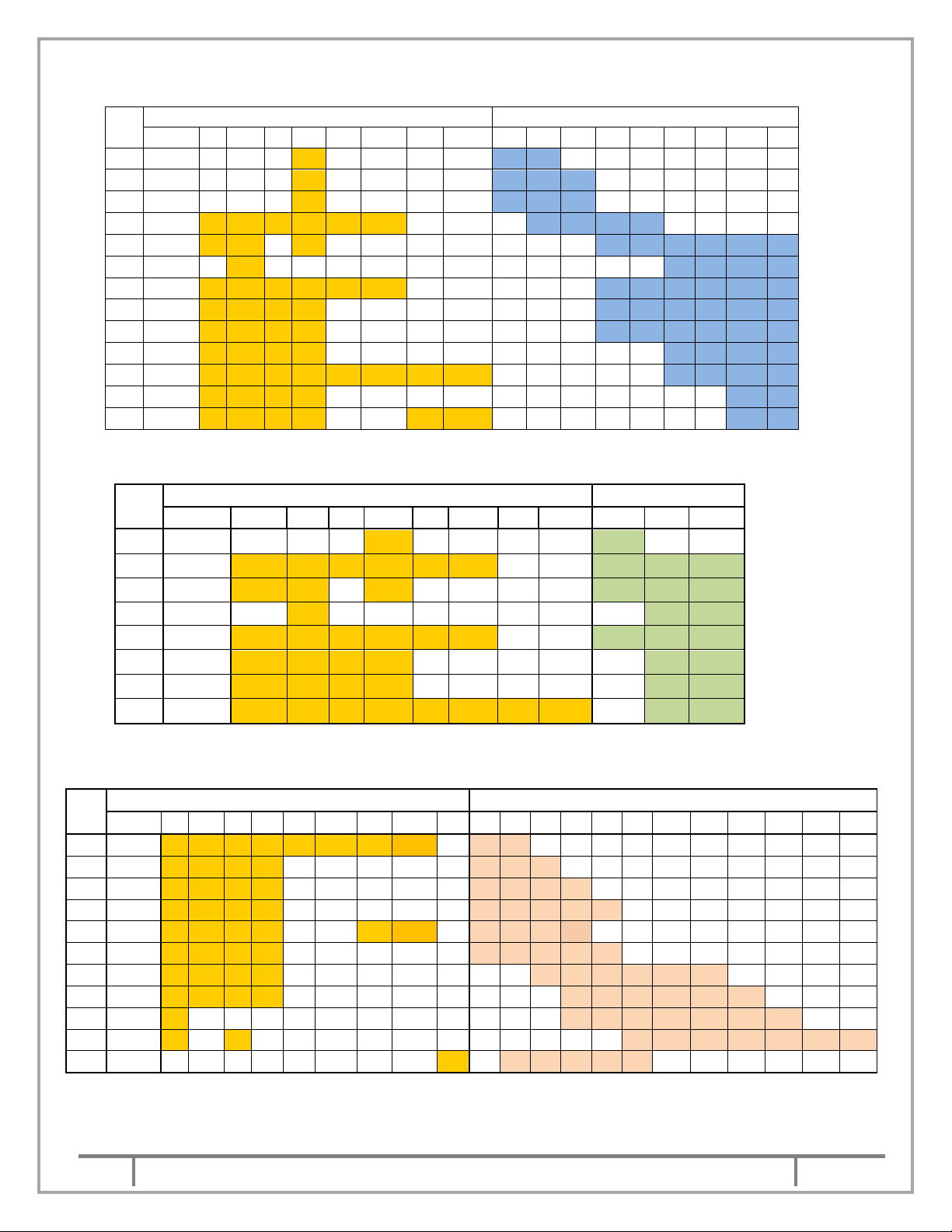
The following charts can be referred to know the pumps available in type of impellers ratings.
A. Refer below chart for 2 pole Models: (iNS)
IMPELLER kW RATING IN 2 POLE
Sr.
No.
PUMP QT 0.75 1.1 1.5 2.2 3.7 5.5 7.5 9.3 11 15 18.5 22
1 20/13
2 20/16
3 20/20
4 32/13
5 32/16
6 40/13
7 40/16
8 40/20
9 50/13
10 50/16
11 50/20
12 65/13
13 65/16
developed. #-yet to develop.
How to read – NS20/13QT 1.1/2 i (i-stands for iNS)
* * * * * *
30
75-110
132-180
-
*-design
5
NS IOM MANUAL
This is a proprietary document of Kirloskar Brothers Limited,
YAMUNA’ Survey No. 98/ 3 to 7, Baner, Pune
– 411045, India.
1
Sept
2018
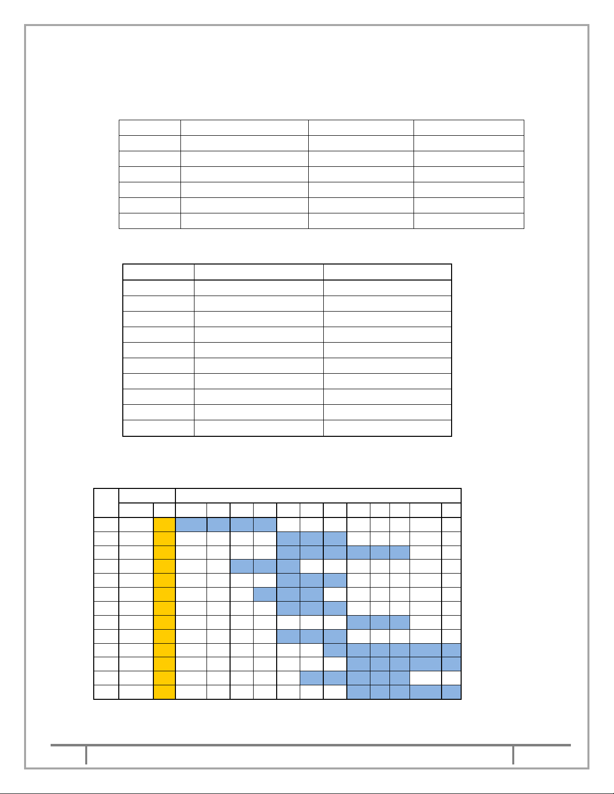
B. Refer below chart for 4 pole Models: (iNS)
* * *
* * * *
* * * *
* * * * * * * * * *
* * * * * * * * *
* * * * *
* * * * * * * * * * * *
* * * * * * * * * *
* * * * * * * * * *
* * * * * * * *
* * * * * * * * * * * *
* * * * * *
* * * * * * * *
* * * * * * * *
* *
* * * *
* * *
* * * *
* * * *
* * * *
* * * * *
* * * *
* *
* * * *
* * * *
* * * * *
* * * *
* * * * * *
* * * *
* * * * * *
*
* * * * * * *
*
*
* * * * * * *
* * * * * *
Sr.
No.
PUMP N QM Q QT NB QMB NM QMM 2.2 3.7 5.5 7.5 9.3 11 15 18.5 22
1 40/20
2 40/32
3 50/20
4 50/26
5 50/32
6 50/36
7 65/32
8 80/26
9 100/26
10 100/32
11 150/26
12 150/32
13 80/40
IMPELLER TYPE kW Rating in 4 pole
C. Refer below chart for 6 pole Models: (iNS)
Sr.
No.
PUMP N QM Q QT NB QMB NM QMM 2.2 3.7 5.5
1 40/32
2 50/26
3 50/32
4 50/36
5 65/32
6 80/26
7 100/26
8 150/26
* * * * * *
* * * * * *
* * *
* * * * * * * * *
* * * * * *
* * * * * *
* * * * * * * * * *
IMPELLER TYPE kW Rating in 6 pole
*
*
* * *
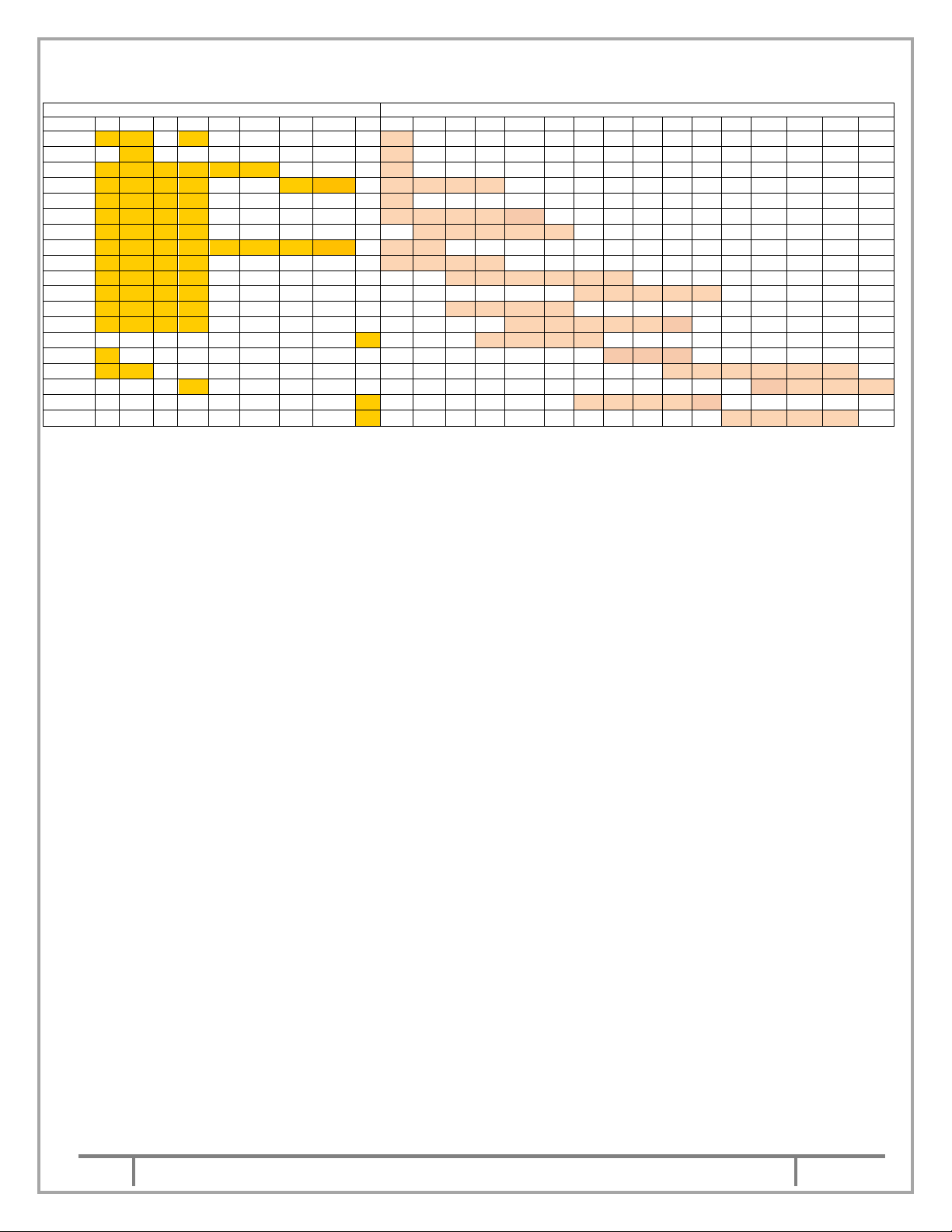
D.
Refer below chart for 4 pole Models: (NS).
Sr.
No.
PUMP N QM Q QT NB QMB NM QMM X 30 37 45 55 75 90 110 132 160 180 200 225
1
150/26
2
100/32
3
150/32
4
200/32
5
80/40
6
100/40
7
150/40
8
200/40
9
250/40
10
150/50
11
250/34
IMPELLER TYPE kW RATING IN 4 POLE
How to read – NS150/26Q 30/4
6
NS IOM MANUAL
This is a proprietary document of Kirloskar Brothers Limited,
YAMUNA’ Survey No. 98/ 3 to 7, Baner, Pune
– 411045, India.
1
Sept
2018
E.
Refer below chart for 6 pole Models: (NS)
PUMP N QM Q QT NB QMB NM QMM X 7.5 9.3 11 15 18.5 22 30 37 45 55 75 90 110 132 160 180
50/32 * * *
50/36 *
65/32 * * * * * *
80/40 * * * * *
100/26 * * * *
100/32 * * * *
100/40 * * * *
150/26 * * * * * * *
150/32 * * * *
150/40 * * * *
150/50 * * * *
200/32 * * * *
200/40 * * * *
250/34
250/40 *
250/50 * *
300/55 *
350/40
350/47
IMPELLER TYPE
*
*
*
*
* * * *
*
* * * * *
* * * * *
*
* *
* * * *
* * * * * *
* * * * *
* * * *
* * * * * *
* * * * *
* * *
* * * * * *
* * * *
* * * * * *
* * * * *
kW RATING IN 6 POLE
1.2
The pump comprises of three units:
I.
II.
III.
Pump unit – It comprises of a delivery casing having wide volute opening and non-clog
type of impeller. The casing is attached with connector unit or stand as per order.
Stuffing box unit – It comprises double mechanical seal and mechanical seal housing
filled with oil for lubricating the seals. The seal behind the impeller is having seat ring of
silicon carbide V/s silicon carbide and second seal comprises of carbon ring V/s stainless
steel ring.
Electrical motor unit – These pumps are provided with submersible three phase squirrel
cage induction motors in watertight housing. The entire motor unit is air tested to ensure
the leak tightness of the joints. Moisture sensor is provided in the mechanical seal housing
to give the indication to control panel which in turn trips the motor, when the seal near
impeller fails. The pump is provided with high and low liquid level controllers which avoids
dry running of pump
.
1.3 The NS pump can be supplied in portable or with fixed arrangement. When the pump is supplied
with portable type, hose, connection should be provided to avoid weight of pipe line on the pump
casing. The casing is provided with stand for support. For stationary application, the pump is
mounted on the support bracket and is connected to the delivery bend through a rubber diaphragm
and connector unit. The pump slides over the guide pipes without disconnecting/disturbing the
delivery pipe line
.
1.4 NS pump is supplied with wall mounted control panel. These control panels are supplied either with
DIRECT ON LINE, STAR DELTA, SOFT STARTER or ATS type starters. These panels are
designed for smooth running of pump-set. The pump gets switched off automatically and is
protected against the following.
a. Contamination of oil with pumped liquid.
b. Dry running of pump.
c. Single phasing/reverse phasing.
d. Over load.
e. Overheating of winding [against order].
The coding of leads of the cables is clearly marked on each lead and the connections to the control
panel should be made as per connections diagram of control panel and s per below shown Figure
(1) & (2).
7
NS IOM MANUAL

This is a proprietary document of Kirloskar Brothers Limited,
YAMUNA’ Survey No. 98/ 3 to 7, Baner, Pune
– 411045, India.
1
Sept
2018
ELECTRICAL CONNECTION DIAGRAM
( STAR DELTA STARTING )
CONTROL CABLE LEADS
M1 & M2 : FOR MOISTURE SENSOR
T1 & T2 : FOR THERMISTER
CABLES FROM PUMP
ELECTRICAL CONNECTION DIAGRAM
EARTHING
E
T2
T1
M2
M1
A1
POWER
B1
C1
B2
C2
CONTROL CABLE LEADS
M1 & M2 : FOR MOISTURE SENSOR
T1 & T2 : FOR THERMISTER
CABLE
LEADS
A2
( DOL STARTING )
CABLE FROM PUMP
M1
M2
EARTHING
E
T2
T1
A
POWER
B
CABLE
LEADS
C
Fig (1) SDS CONNECTION
Fig (2) DOL CONNECTION
1.5 As a standard scope of supply, NS pumps are supplied with 5 or 10 m long cable. This cable
consists of power cable having 4 and 3 core for Star Delta starting (for rating from 11kW to 22kW)
and 4 core cables for DOL (for rating upto 9.3kW) starting suitably designed for the voltage and
current. The control cable of 4 cores 1.5 sq.mm is used for thermistor and moisture sensor 2 wires
each.
2.
Safety Instructions:
2.1: General Information
Before performing any actions detailed within this instruction, the Site Health and Safety
instructions shall be read and fully understood. The instructions in this document shall also be read
and fully understood.
Whenever the equipment is operated, maintained or used in any way, the procedures detailed
within the Health and Safety Dossier (DHS) and any procedures detailed within these instructions
shall be followed. The pump supplied by Kirloskar Brothers Limited (KBL) has been designed with
safety in mind; where hazards cannot be eliminated, the risk has been minimized using guards and
other design features. Some hazards cannot be guarded against and the instructions below MUST
BE COMPLIED WITH for safe operation. These instructions cannot cover all circumstances. It is
the responsibility of the user of the equipment for maintaining safe working practices always. The
pumps are supplied with stickers for hazard, caution and safety wherever these are applicable.
2.1.1 Within the manual, safety instructions are marked with safety symbols.
Hazard.
a. This symbol refers to general
mechanical aspects of safety.
c.
This symbol refers to electrical
safety.
d.
b. This symbol is used to
introduce safety instructions
whose non- Observance may
lead to damage to the machine and its functions.
e.
This symbol refers to
magnetic field safety.
8
NS IOM MANUAL
This is a proprietary document of Kirloskar Brothers Limited,
YAMUNA’ Survey No. 98/ 3 to 7, Baner, Pune
– 411045, India.
1
Sept
2018
f. This symbol refers to restrict person having heart pacemaker to avoid contact
with magnetic components while pump is in running condition or while
carrying out maintenance work of pump.
2.1.2 KBL products are designed for installation in designated areas, which are to be kept clean and free
of obstructions that may restrict safe access to the controls and maintenance access points.
Pump nameplate is fitted to each unit and must not be removed. Loss of this plate
could make identification impossible. This in turn could affect safety and cause
difficulty in obtaining spare parts. Should accidental loss or damage occur, contact
KBL immediately.
2.1.3 Access to the equipment should be restricted to the personnel responsible for installation, operation
and maintenance and they must be trained, adequately qualified and supplied with the appropriate
tools for their respective tasks.
2.1.4 KBL firmly insists that all personnel responsible for installation, operation and maintenance of the
equipment must read the manual before any work is done.
2.1.5 Ear defenders should be worn where the specified equipment noise level exceeds locally defined
safe levels. Safety glasses or goggles should be worn where working with pressurized systems
and hazardous substances. Other personal protection equipment must be worn where local rules
apply.
2.2 DO NOT wear loose or frayed clothing or jewellery, which could catch on the
controls or becomes trapped in the equipment.
2.3 Operation of the equipment for the application other than for which it is supplied can increase the
risk from hazards. Please consult KBL before making such change in the application of the
equipment.
2.4 Improper installation, operation and maintenance of the product supplied by KBL could result in
injury or death.
2.5
2.6 In case of NS pumps which are handling fluid at high temperature, the operator
should avoid touching the pump in running condition. Use safety equipments like hand gloves and
safety shoes while operating NS pumps in such applications.
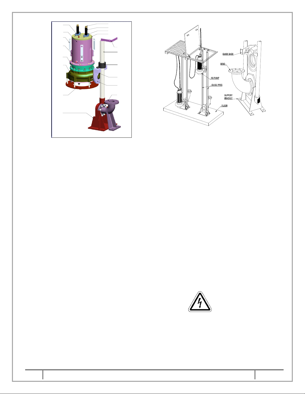
3. INSTALLATION:
3.1 The NS pumps of stationary arrangement are supplied with pump connector unit and this
connector unit is connected to pump support bracket with guide shoe & rubber diaphragm
to make it leak proof joint.
9
NS IOM MANUAL
This is a proprietary document of Kirloskar Brothers Limited,
YAMUNA’ Survey No. 98/ 3 to 7, Baner, Pune
– 411045, India.
1
Sept
2018
BOL TS
MOT OR E ND
CO VER
CAB LE
BRA CKET
STA TOR
HOU SING
STU FFIN G
BOX BUS H
CAS ING
STA ND
SUP POR T
BRA CKE T
EYE
CAB LE
CAB LE P ROT ECTIO N
TUB E
CAB LE G LAND
MOT OR E ND
COV ER
HO LDER
GUI DE
PIPE
GUI DE
PIPE
ADA PTER
RUB BER
DIAP HRA GM
GUI DE
SHO E
DUC K FO OT
BEN D
Single guide pipe arrangement (iNS) Double guide pipe arrangement
Stationary Installation view.
3.1.1 Installation of support bracket & bend –
Before installing the pump, ensure that sump bottom is flat and leveled. The support bracket &
bend should be attached and fixed to the sump bottom with foundation bolts, so that the guide pipe
shall be exactly vertical.
Ensure that support bracket and bend are located correctly relative to descending pump vertical
guide pipe and discharge pipe.
3.1.2 Lowering the pump - Attach the guide shoe & guide pipe adapter to the pump. The unsupported
length of guide pipe should not exceed 6 m.
3.1.3 Fix the guide pipe in the support bracket and locate the vertical position of guide pipe holder at the
top of the pit. Now grout the guide pipe holder.
3.1.4 Insert the above assembly in the guide pipe by dismantling the guide pipe holder & refit the holder
in the guide pipe.
3.1.5 Check- Lower the pump with the help of chain. While sliding over the guide pipe into the sump,
check that the cable is not slagging and is not under tension.
3.1.6 Ensure that the pump position is exactly vertical on the support bracket. Check by giving a jerk.
3.1.7 Before taking the pumping station into use, check that there are no loose solid pieces or other
material on bottom of sump that would damage the pump.
3.1.8 DO NOT LIFT THE PUMP WITH THE HELP OF CABLES.
3.2 The NS pumps supplied for portable installation requires no foundation. Only ensure that the
delivery pipe line is well supported and its weight is not acting on pump casing directly.
3.3 Use chain with intermediate hooks for holding to lower or lift the pump. This type of chain is specially
designed to avoid the tendency of the operator to lift the pump with the help of cable causing
damage & replacement of the cable unit. While selecting size of the chain, refer weight of the pump
given in 7.6. and chain capacity as per chart in 3.4. We recommend use of non-return valve in
delivery pipe line located before sluice valve.
10
NS IOM MANUAL
This is a proprietary document of Kirloskar Brothers Limited,
YAMUNA’ Survey No. 98/ 3 to 7, Baner, Pune
– 411045, India.
1
Sept
2018
3.4 As per IS: 2429 the following sizes of chains can be used upto the weight as mentioned in the
Nom. Chain Size (mm)
Lifting capacity (Tonnes)
6
8
10
12
14
16
below chart.
0.44
0.8
1.25
1.8
2.4
3.2
4. OPERATION:
4.1 Prior to commissioning of the pump, check the following.
FILL THE OIL INSIDE THE MECHANICAL SEAL HOUSING WITH PROPER GRADE REFER CHART IN
7.5 OF CLEAN OIL FREE FROM MOISTURE. ENSURE THE MECHANICAL SEAL HOUSING OF THE
PUMP IS DULY FILLED AS PER CHART IN 7.6. CHECK THE OIL PLUG OF THE MECHANICAL SEAL
HOUSING IS INTACT.
4.1.1 Check the insulation resistance of winding by using 500 V megger. The insulation resistance of
winding should not be less than 10 mega-ohms for motor rating upto 45kW and 50 mega-ohms
beyond 45kW at phase to phase and phase to Earth. This test should be carried out at free end of
the cable. If the insulation resistance is found less than mentioned above then please consult our
service personnel.
For continuity test, connect the two wires of megger between the two ends of the same phase of
motor. It should show zero resistance. This test should be carried out for the phases.
The resistance across two moisture sensing wires M1 and M2 should be above 5 MΩ. Make sure
to remove control cable connections from terminal board [M1 and M2] before testing this. If the
resistance found less, please consult our service department. The megger test for phase to phase
and phase to Earth should be conducted serially. The megger test should show insulation
resistance above 10 MΩ for motor rating upto 45kW and 50 MΩ beyond 45kW
4.1.2 The control panel is provided with auto/manual switch. When the switch is on "Manual" position the
pumpset can be started manually by the start push button provided the liquid level is above the low
level electrode. If the switch is on "Auto" position it will start automatically if liquid level in the sump,
is above the high-level electrode. The pump set gets switched off automatically for any position of
Auto Manual switch if liquid level goes down just below the low-level electrode. This is indicated by
glowing of red lamp on control panel.
When the pumped liquid gets mixed up with the oil in the casing cover, it is indicated by glowing of
red lamp under name plate contamination. After rectification of the fault, resetting switch is to be
pressed first and then the pump set will get started by pressing "Starting switch" if it is operated on
"Manual position" or automatically if control panel is operating on "Auto position".
Before change over from star to delta connection, time delay should be sufficient to allow the motor
to attain its normal running speed. The same depends upon the load of the motor and it is generally
around 10 second.
4.1.3 LIQUID LEVEL CONTROLLERS ARE INCORPORATED IN THE PANEL TO PROTECT THE
PUMP FROM DRY RUNNING. THE LOW-LEVEL ELECTRODE SHOULD BE POSITIONED IN
SUCH A MANNER THAT LOWEST END OF ELECTRODE REMAINS ABOVE MOTOR BODY. IF
LOW LEVEL ELECTRODE IS NOT INSTALLED PROPERLY THE MOTOR BODY IS LIKELY TO
BE HEATED UP AS COOLING OF MOTOR IS DONE BY LIQUID IN THE SUMP AROUND THE
STATOR HOUSING. HENCE SUBMERGENCE UPTO FULL CORE LENGTH OF MOTOR IS
REQUIRED.
4.1.4 Before starting the pump, check the direction of rotation is as outlined below.
.
11
NS IOM MANUAL

This is a proprietary document of Kirloskar Brothers Limited,
YAMUNA’ Survey No. 98/ 3 to 7, Baner, Pune
– 411045, India.
1
Sept
2018
4.1.5 Hoist up the pump and momentarily switch on the power. If the connections are correctly made the
pump should jerk in anticlockwise direction when viewed from top. If the pump jerks in opposite
direction, change two phases of the incoming leads to the control panel. In no case the direction of
rotation should be changed by changing the leads of motor terminals. Do not run the pump dry.
Just check in which direction the pump jerks.
4.2 While putting the pump in operation, follow the procedure outlined below.
4.2.1 Start the pump. Let the motor pick-up its full speed.
4.2.2 Open the discharge valve slowly.
4.3 Check during running that –
4.3.1 The pump is running smooth.
4.3.2 Power consumption is within limit.
4.3.3 Head and capacity developed by the pump is as specified.
4.3.4 Stop the pump immediately if any defects are detected and must not be started unless they
are rectified. Report immediately to the supplier if it is not possible to rectify the defect.
4.4 STOPPING THE PUMP:
4.4.1
Pump should be switched off only after closing the delivery sluice valve.
5. MAINTENANCE:
Preventive maintenance schedule is the periodical checks and precautions by which possibilities
of failure and break-downs are minimized.
5.1 Daily checks –
5.1.1 An hourly record of the delivery pressure and power input to the pump should be maintained.
5.1.2 Noise and vibrations is the first sign of impending troubles like bearing failure, choking of impeller
or casing and such other operating troubles. The pump performance should be checked for noise
and vibration.
5.2 Periodical checks –
5.2.1 The lubrication of mechanical seals should be checked. The lubricant might get contaminated with
foreign material or get blackened due to overheating. In such cases, oil chamber should be flushed
and filled with fresh oil. Before filling, heat the oil [Servo system 317] to 140°C. This is required to
remove moisture present in the oil.
5.2.2 THE ELECTRODES/FLOAT SWITCHES SHOULD BE CLEANED WHENEVER POSSIBLE BUT
NOT LATER THAN 15 DAYS FOR SMOOTH WORKING OF PUMP.
5.2.3 Clean the sump if there are chances of deposition of the contents of liquid handled.
5.2.4 Replace the Oil from pump periodically after 2000 hrs.
5.3 Annual checks [after one year minimum] –
5.3.1 The pump portion of the motor pump set should be overhauled completely to check the clearance
and to replace the worn-out parts. Clearance between impeller and casing ring and casing cover
are very important.
5.3.2 The effect of liquid handled on pump components should be checked. If abnormal corrosion,
erosion is observed then the components should be replaced with that of suitable material.
12
NS IOM MANUAL
 Loading...