

KIRLOSKAR KOSN Series Installation, Operation & Maintenance Manual
Kirloskar “KOSN Series”
Centrifugal Submersible Pump
A Kirloskar Group Company
KIRLOSKAR BROTHERS LIMITED
INSTALLATION, OPERATION & MAINTENANCE MANUAL
KOSN Series
CM - 9862
WORKS :
Ujjain Road, Dewas - 455 001 (M.P.)
Phone : +91 7272 227401/2/5/9 Fax : +91 7272 228747
Toll Free No. 1800 103 4443
CORPORATE OFFICE :
“YAMUNA”, Survey No. 98 (3-7), Baner,
Pune 411 045 (India)
Phone : +91 20 27214444
E-mail : kblin@kbl.co.in Visit us at : www.kirloskarpumps.com
REGISTERED OFFICE :
Udyog Bhavan, Tilak Road,
Pune - 411 002 (India)
Tel. : +91 20 24444444 Fax : +91 20 24444198
E-mail : kbl@kbl.co.in
KIRLOSKAR BROTHERS LIMITED
A Kirloskar Group Company
A View of KBL Dewas Manufacturing Plant
06019860

FOR PROMPT SERVICE & SPARES
Register on our website : www.kirloskarpumps.com
Our products are meant for pumping
water and they do not have any significant effect
on environment during their use, if properly
selected and used as per instructions
given in this manual.
Customers are advised to dispose unusable
components through appropriate disposal agencies to
avoid the impact on work environment.
CONGRATULATIONS........... .
Congratulations.... ..... on you r acqui ring one of t he finest pumps in t he
country.
The Kirloskar Openwell Submersible New- version Series in your
possession is scientifically designed by using the state of art design software
(Pro/E, ANSYS, CFD) for better a esthetics, performance, optimum material
Contents etc. These pumps are reliable, robust, compact in size and cheaper in
their class. Ca reful selection of materials, manufacturing and testing assur es
you a satisfactory performance over a long period of time.
These pumps will give you years of trouble free performance if it is
handled with due care. This booklet is a step in this direction. It covers general
instructions on installation, operation and maintenance of KOSN Pumps. Please
read this booklet comply with the instructions and your pump is bound to serve
you well.
1. HANDLING 01
2. PUMP DESIGNATION KEY 01
3. FEATURES & APPLICATION 01
4. OPERATING CONDITION 02
5. INSTALLATION 02
6. ELECTRICAL CONNECTION 04
7. PRIMING 05
8. MAINTENANCE 05
9. TROUBLE SHOOTING CHART 06
10. CAUSE AND REMEDY CHART 07
11. DISMENTLING PROCEDURE 12
12. DISPOSAL 12
13. EXPLODED VIEW 13
14. PART LIST 14
15. OUTLINE DRAWING 15
16. PUMP MODELS 16
17. PRODUCT RANGE 17
18. WARRANTY CERTIFICATE 18
CONT ENTS

1. Handling : When the entire pump is to be lifted in vertical direction, th en it is
recommended to lift the pump at the Lifting bolt by means of straps/ropes as shown in
figure 1.1 If pump to be moved from one place to another place then it is recommended to
lift the pump at mounting casing by means of hand.
figure 1.1
2. Pump designation key : Following 7 key characters designate Kirloskar KOSN
series monoblocs.
Example KOSN-128
K O S N 1 28
Name of Type of Type of Version Power Head at 0
firm pump pump rating in HP discharge
Kirloskar Open Well Submersible New 1 for 1 HP Sh ut of
1.5 for 1.5 head
HP etc
3. Features:
Kirloskar Openwell Submersible New version Pumps of designed for a wide
range of applications.
Designed for underwater applications - No need of priming and foot valve.
Easy installation - Foundation and installation platform or pump house not
required .
Can withstand wide voltage fluctations from 160-260 V.
Desined to prevent overloading and motor burning.
1
LIFTING ROPE
Dynamically balanced rotating parts to ensure minimum vibrations during
running .
Replacable wearing parts and hence longer life .
Easy maintenance and spares availability .
Applications :
Submerged pump in Fountains, Wells, Sumps and Water tanks .
Water supply for domestic use in high rise Apartments, Buildings and Hotels.
Gardening and sprinklers/conventional irrigation .
Industries, for clear water handling .
2
4. Operating Conditions :
4.1 Pumped Liquids :
Kirloskar Openwell Submersible New version Pumps are suitable only to pump
thin, non-explosive liquids, not containing solid particles. The liquid must not attack the
pump materials chemically. When pumping liquids with density and/or viscosity higher
than that of water, suitability of motor winding with correspondingly higher outputs must
be checked, if required.
4.2 Submerged Condition :
The pump must be submerged in water more than 1 meter .
4.3 Technical Data :
Maximum Liquid Temperature - 500 C
Rated voltage - 210 volt for single phase
- 380 volt for three pahse
Voltage Range - 160-260 for single phase
350-415 for three phase
Type of Duty - S 1 continuos
Direction of rotation - Anti-clock wise form suction side.
Frequency - 5 0Hz
Sound Level - 80dB
Degree of protection - I P-68
Class of Insulation - ‘P P’
5. INSTALLATION
5.1 G uidelines :
For avoiding the un-necessary troubles in Installation, Operation Ma i nt en an c e
and for Utmost Performance of the Pump, we are suggesting few guidelines. We hope by
following these guidelines our customer will able to install the pump easily and operate
the pump at optimum performance.
3
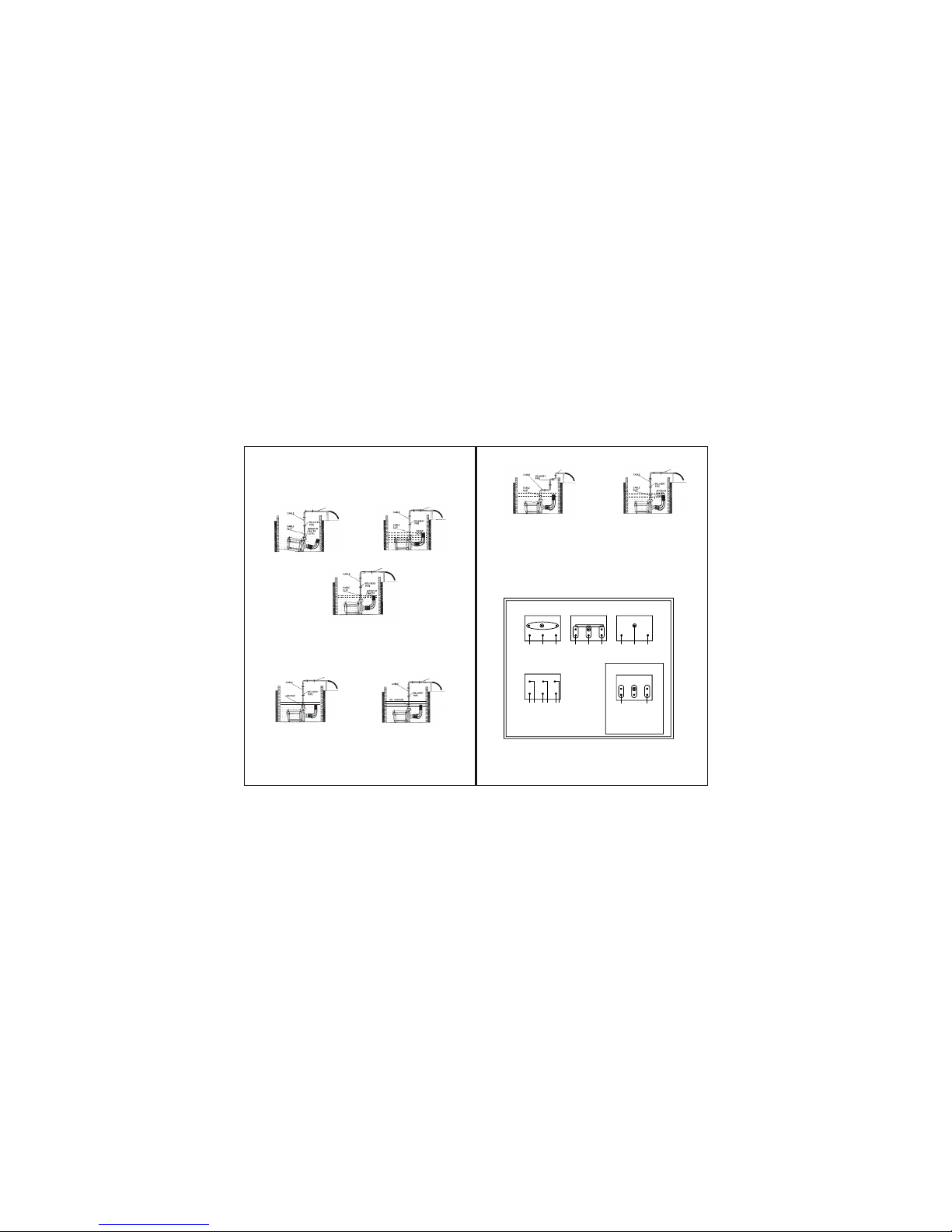
WRONG WRONG
Fig. 5.1
5.2 Guideline for Installation :
5.2.1 Location : The pump should be installed in horizontal position and submerged in
the water more than 1 meter . This will eliminate dry run and pump will give better
performance. The pump does not require any foundation ; however if installing dug
cum borewell , surface should be plain . The pump should not be installed in tilted
position. (Ref. fig. 5.1)
5.2.2 Guideline for Piping :
ØPipe size should be as per flange size to g et h igher dischar ge. It i s n ot
recommended to reduce pipe size. If length of delivery pipe is more than 3 m., use
hig her p ipe (P leas e refe r tabl e 1.1 a nd 1. 2 for pr oper pipe s ize) .
ØThe pi ping shoul d be airt ight . A ny leak age in p ipe may d rast icall y
affect the performance of the pump. ( ref. fig. 5.2 )
ØThe suction pipe should be as short as possible for getting better dischar ge.
( in case of dug cum borewell type arrangement. )
ØNo. of bends and other fittings should be as minimum as possible to reduce
frictional losses. ( ref. fig. 5.3 )
ØAdequate supports should be provided to pipes so that its dead weight should
not fall on delivery casing completely.
RIGHT
Fig. 5.2
RIGHT
6 Guideline for Electrical Connections :
ØProper earthing connection should be made at the bolts provided for earthing.
ØProper size of cable should be used between supply and motor terminals to
minimize voltage drop and to carry full load current (FLC) as well as the maximum
current in the operating voltage range specified.
4
ØFor delivery pressure more than 20 meters, it is recommended to install a check
( non-return ) valve in the discharge line. The check valve placed near the pump
is to protect the pump from excessive backpressure to prevent the water running
back through the pump in case of sudden failure of prime mover .
No. OF LEADS 3
V1 U1
W1
U1
V2
W2
CONNECTION
STAR OR DELTA
No. OF LEADS 3
V
U
W
TO LINES
STAR DELTA STARTING
No. OF LEADS 6
V2U2V1W2
W2 U1
CONNECTION DIAGRAM OF
THREE PHASE MOTORS
LEADS FROM
MOTOR
SINGLE PHASE 50 Hz
SUPPLY
CONNECTION DIAGRAM OF
SINGLE PHASE MOTOR
PHASE NEUTRAL
ØNuts at terminal should be tightened properly.
ØNo. of joints in cable should be less as possible, preferably joints should be
avoided.
Fig. 5.3
WRONG
CORRECT
 Loading...