

KIRLOSKAR GK Series, GKP Series, GK 7A, GKP 7A, GK 10 Instruction On Installation, Operation And Maintenance
...
INSTRUCTIONS ON
INSTALLATION,
OPERATION AND
MAINTENANCE FOR
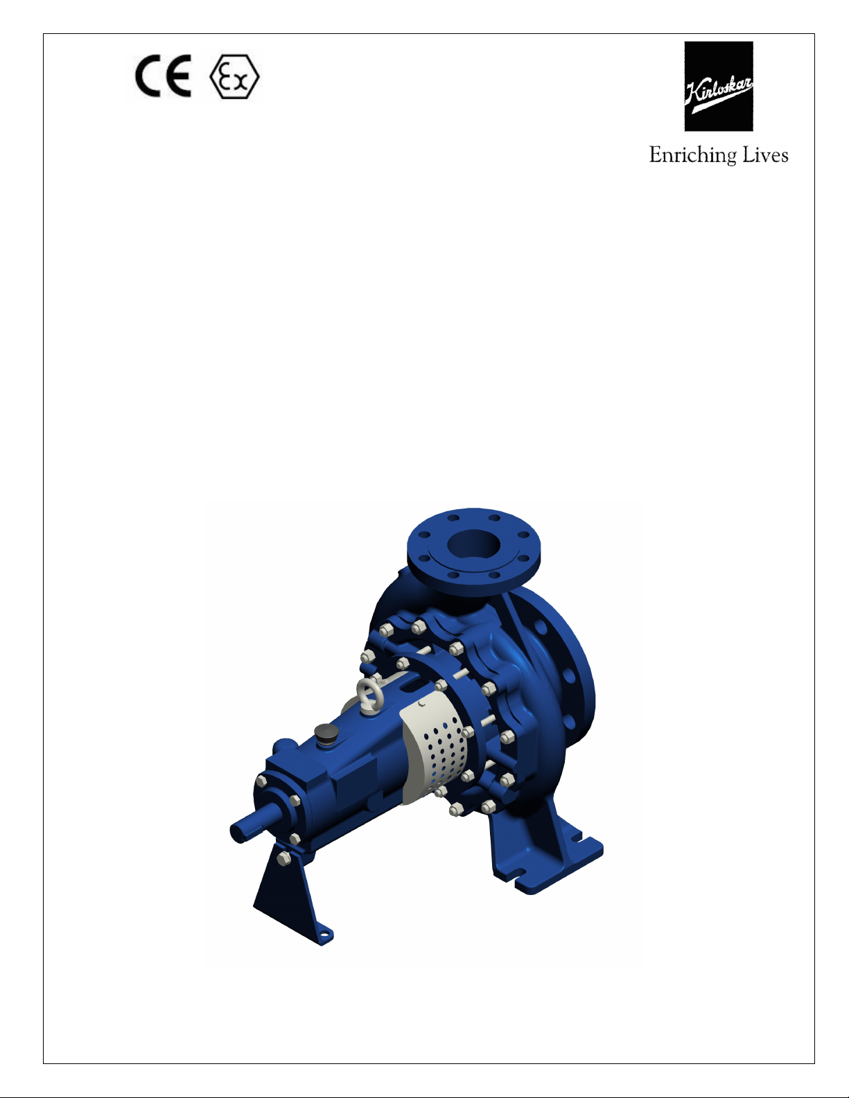
KIRLOSKAR PUMP
TYPE GK(P)
IOM/GK(P)/CONICAL ISSUE DATE: 10.11.2015
Page 1 LAST REV. DATE: 01.08.2019
KIRLOSKAR BROTHERS LIMITED
REGD. OFFICE UDYOG BHAVAN, TILAK ROAD PUNE-411002
WARRANTY
We warrant that the pump supplied from us is free from defective
material and faulty workmanship. This warranty holds good for a
period of 12 months from the date of commissioning the equipment
or 18 months from the date of dispatch from our factory, whichever
is earlier. Our liability in respect of any complaint is limited to
replacing part/parts free of charge ex-works or repairs of the
defective part/parts only to the extent that such replacement / repairs
are attributable or arise solely from faulty workmanship or defective
material.
This warranty holds good only for the products manufactured by us.
KIRLOSKAR BROTHERS LIMITED
IOM/GK(P)/CONICAL ISSUE DATE: 10.11.2015
Page 2 LAST REV. DATE: 01.08.2019

CONTENTS
PART A: ATEX SAFETY MANUAL
PART B:
INSTRUCTIONS ON INSTALLATION, OPERATION AND
MAINTENANCE FOR KIRLOSKAR PUMP TYPE GK(P)
1. GENERAL
2. SAFETY INSTRUCTIONS
3. EQUIPMENT SCHEDULE
3.1 INSTALLATION
3.2 MOUNTING AND ALIGNMENT
4. OPERATION
4.1 EQUIPMENT DESCRIPTION
4.2 EQUIPMENT OPERATION
5. MAINTENANCE MANUAL
5.1 MAINTENANCE EHS INSTRUCTIONS
5.2 GENERAL MAINTENANCE DOCUMENTS
5.3 PREVENTIVE MAINTENANCE
5.4 CORRECTIVE MAINTENANCE
6. TECHNICAL DATA
Note: A copy of
maintenance of ‘Kirloskar pumps’
General instructions for installation, operation &
is attached at the end of this
manual.
IOM/GK(P)/CONICAL ISSUE DATE: 10.11.2015
Page 3 LAST REV. DATE: 01.08.2019
PART A: ATEX SAFETY MANUAL
TRAINING
It is recommended and a part of the CE regulations that users personnel who will be
involved in the installation, operation and/or maintenance of KBL products should
have the opportunity of an initial training period, which can be carried out either at
KBL works or customers premises by arrangement.
This training is offered by KBL in 3 different forms.
A. Informal training in your maintenance workshop by our Technical Sales
Representative on a Free of Charge basis.
B. Formal training in your training rooms by our skilled training personnel using
visual aids, ‘hands on’ equipment, etc., at an agreed cost to be confirmed.
C. Formal training at KBL Premises by our skilled training personnel using visual
aids, ‘hands on’ equipment, etc., at an agreed cost to be confirmed.
It is your responsibility to request your preferred training method now. KBL will not
consider responsibility for ongoing breakdowns, etc., if training has not been given.
KBL offer a friendly after sales policy but, reserve the right to charge for “call out”
visits that are found to be caused through operator/fitter error.
LIMITATIONS OF USE
KBL products are designed to provide performance generally, as shown in
accompanying literature associated with the individual models or series. All
performance Figures are given in good faith and are based on tests at KBL works
using water at ambient temperature.
Operating temperatures are governed by the materials of construction of parts i.e.
bearings, shaft gland, sealings, seals, etc., and it is the installer’s responsibility to
ensure that these maximum temperatures are not exceeded under any
circumstances.
Performance Figures provided by KBL against individual enquiries are estimates only
and are subject to variations depending upon atmosphere pressure and volumes of
liquid provided by client, and to head losses due to pipe work, valves, etc., which
may be unknown to KBL estimators.
All performance Figures, temperatures, flow rates, dimensions & other details are
subject to change without notice. Due to the wide variety of products handled by
KBL pumps, it is impossible for KBL to give a firm recommendation regarding
materials of construction for pump components. It is the users or specifiers
responsibility to determine the effect of corrosion & abrasion, and the general
suitability of any pump supplied for any individual application. KBL will, however,
give advice in such material selection as it may be able to do so in good faith.
IOM/GK(P)/CONICAL ISSUE DATE: 10.11.2015
Page 4 LAST REV. DATE: 01.08.2019

ESSENTIAL SAFETY REQUIREMENTS (ESR)
ATEX DIRECTIVE 2014/34/EU (EXPLOSION HAZARD SAFETY)
All KBL products that are certified to comply with the Directive also carry a specific
ATEX Safety Manual (Section 5) which must be referred to in conjunction with this
manual. It is the responsibility of the user to ensure that the equipment is correctly
rated for the environment in which it is to be used.
When handling KBL products, please refer weights given in KBL literature. Lifting
equipment may be required in certain cases. Note that all pumps dispatched from
our works are tested with water and during storage, packing and installation, some
water will have remained in the pump body. This water may cause spillage during
handling. Water could react with the products you wish to pump, and it is your
responsibility to check this before putting the pump into operation. Water may also
freeze if the pump is exposed to sub zero temperatures. Do not operate the pump
under these conditions as ice inside the pump may cause damage to working parts
of the pump.
At all times the installer must wear suitable clothing, footwear, goggles, etc., for
personal protection. This particularly applies when the pump is being operated or
maintained.
If the product being processed is hazardous, then provision must be made by the
user to deal with this problem. This can be achieved by either specifying a guardian
or barrier system as part of the original pump specification and constructing pipe
work which can carry the leakage to a safe place.
ATEX SAFETY MANUAL
For Centrifugal GK(P) Pumps and Accessories.
User Instructions to ensure compliance with European Directive 2014/34/EU
1.0 GENERAL
These instructions must always be kept close to the product’s operating location or
directly with the Product. These instructions are intended to facilitate familiarization
with the product and its permitted use to help satisfy ATEX safety requirements.
The instructions may not have taken into account local regulations; ensure such
regulations are observed by all, including those installing the product. Always coordinate repair activity with operations personnel and follow all plant safety
requirements and applicable safety and health/law regulations. These instructions
should be read prior to installing, operating, using and maintaining the equipment in
any region worldwide and in conjunction with the main user instructions provided.
The equipment must not be put into service until all the conditions relating to safety
instructions have been met.
IOM/GK(P)/CONICAL ISSUE DATE: 10.11.2015
Page 5 LAST REV. DATE: 01.08.2019

A.1 DIRECTIVE 2014/34/EU
It is a legal requirement that machinery and equipment put into service within
certain regions of the world shall conform to the applicable CE Marking Directives
for Equipment for Potentially Explosive Atmospheres (ATEX).
Where applicable the Directive covers important safety aspects relating to the
equipment, its use and the satisfactory provision of technical documents. Where
applicable this document incorporates information relevant to these Directives. To
establish if the product itself is CE marked for a Potentially Explosive Atmosphere
check the name plate and the Certification provided.
A.1.1 Disclaimer
Information in these User Instructions is believed to be reliable. In spite of all the
efforts of KIRLOSKAR BROTHERS LTD. to provide sound and all necessary
information, the content of this Manual may appear insufficient and is not
guaranteed by KIRLOSKAR BROTHERS LTD. as to its completeness or accuracy.
A.2 Personnel qualifications and training
All personnel involved in the operation, installation, inspection and maintenance of
the unit must be qualified to carry out the work involved. If the personnel in
question do not already possess the necessary knowledge and skill, appropriate
training and instruction must be provided. If required, the operator may commission
the manufacturer/supplier to provide applicable training.
A.3 Maximum surface temperature (Temperature Class)
Special attention must be paid to the marking on the ATEX name plate as the use
of ‘pirate’ spare parts will invalidate the ATEX certification. It is essential to heed
the instruction prohibiting dismantling of the equipment in a flammable atmosphere
where applicable.
EQUIPMENT MUST BE EARTHED AND ONLY GENUINE KBL SPARES USED DO
NOT DISMANTLE IN FLAMMABLE ATMOSPHERE.
A.4 CE Marking & Approvals
General:
It is a legal requirement that the machinery & equipment put into service in certain
region of the world shall conform with the applicable CE marking directives
covering pump, accessories & instruments in the package for potentially Explosive
Atmosphere (ATEX). The applicable documents incorporating information relevant
to their directives will be provided separately e.g. CE marking & ATEX marking
certification, additional safety instructions & directives etc., as applicable.
Kirloskar pumps GK(P) range of pumps are certified to comply with the ATEX
directives 2014/34/EU & user is to ensure compliance with the European Directive
2014/34/EU.
IOM/GK(P)/CONICAL ISSUE DATE: 10.11.2015
Page 6 LAST REV. DATE: 01.08.2019
Check the product name plate & certification provided to establish that the product
itself is CE marked for Potentially Explosive Atmosphere.
Non CE/ATEX marked.
Marking: An example of ATEX equipment marking is shown below. The applicable
marking will be graved on name plate:
Example:
II 2/3 G/D h Tx Gb/Gc
1 2 3 4 5 6 7 8
1) CE marking
2) Use of equipment in potentially explosive atmosphere
3) Equipment group for surface application
4) Equipment Category 2 (Zone 1) or 3 (Zone 2)
5) G-Gas D-dust
6) Constructional Safety ‘h’ as per EN ISO 80079-36 & 37
7) Temperature Class –T1-450ᑻᑻᑻᑻC T2-300ᑻᑻᑻᑻC T3-200ᑻᑻᑻᑻC T4-135ᑻᑻᑻᑻC T5100ᑻᑻᑻᑻC T6-85ᑻᑻᑻᑻC
8) Equipment Protection Level – Gb (Zone 1) / Gc (Zone 2)
A.5 Avoiding excessive surface temperatures
ENSURE THE EQUIPMENT TEMPERATURE CLASS IS SUITABLE FOR THE HAZARD
ZONE
A.5.1 Pump liquid temperature
Pumps have a temperature class as stated in the ATEX Ex rating on the name plate.
These are based on a maximum ambient of 40ºC (104ºF). Refer to KIRLOSKAR
BROTHERS LTD. for higher ambient temperatures. The surface temperature of the
pump may be influenced by the temperature of the liquid handled. The maximum
permissible liquid temperature depends on the temperature class and must not
exceed the values in the table applicable below. The temperature rise at the seals,
bearings and due to the minimum permitted flow rate is taken into account in the
temperatures.
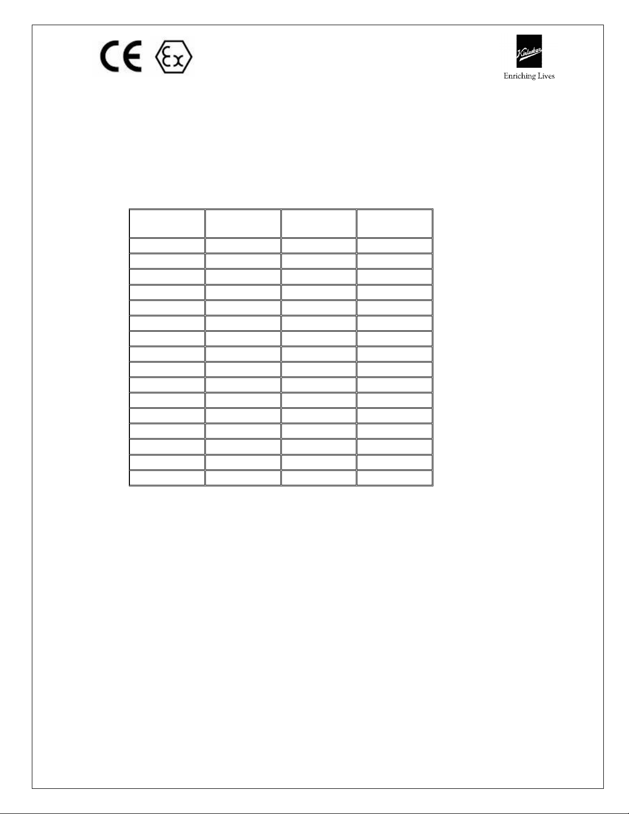
Maximum permitted liquid temperature for GK(P) pumps:
Temperature
Class to
EN 13463–1
Maximum
Surface temperature
Permitted
Temperature limit of
liquid handled
Depending on material
and Construction
variant.
T4 1350C (2750F) 1050C (2210F)
T3 2000C (3920F) 1750C (3470F)
T2
3000C (5720F)
2500C (4820F)
Else product to be treated as
Consult Kirloskar
Brothers Ltd.
Consult Kirloskar
Brothers Ltd.
Consult Kirloskar
Brothers Ltd.
IOM/GK(P)/CONICAL ISSUE DATE: 10.11.2015
Page 7 LAST REV. DATE: 01.08.2019

Where there is any risk of the pump being run for prolonged periods against a
closed or partially closed valve generating high liquid and casing external surface
temperatures, it is recommended that users fit an external surface temperature
protection device.
A.5.2 Additional requirements for self-priming conditions
Where the system operation does not ensure control of priming, and the maximum
permitted surface temperature of the T3 Class could be exceeded, it is
recommended for users to fit an external surface temperature protection device.
A.6 Preventing the build up of explosive mixtures
ENSURE PUMP IS PROPERLY FILLED WHENEVER POSSIBLE AND DOES NOT RUN
DRY FOR LONGER THAN 5 MINUTES CONTINUOUSLY
Ensure the pump and relevant suction and discharge pipeline system is totally filled
with liquid during the pumping operation, so that an explosive atmosphere is
prevented. If the operation of the system cannot avoid this condition, ensure that
the pump does not run dry for more than 5 minutes continuously.
To avoid potential hazards from fugitive emissions of vapour or gas to atmosphere
the surrounding area must be well ventilated.
A.7 Preventing sparks
To avoid the potential hazard from random induced current generating a spark, the
earth stud on the pump casing or foot must be connected. Avoid electrostatic
charge: Do not rub non-metallic surfaces with a dry cloth for cleaning, etc; ensure
the cloth is damp.
A.8 Preventing leakage
The pump must only be used to handle liquids for which it has been approved to
have the correct corrosion resistance. Avoid entrapment of liquid in the pump and
associated piping due to closing of suction and discharge valves, which could cause
dangerous excessive pressures to occur if there is heat input to the liquid. This can
occur particularly if the pump is stationary. Bursting of liquid containing parts due
to freezing, must be avoided by draining or protecting the pump and ancillary
systems. If leakage of liquid to atmosphere can result in a hazard, the installation of
a liquid detection device is recommended.
A.9 Maintenance of the GK(P) pump to avoid the hazard
CORRECT MAINTENANCE IS REQUIRED TO AVOID POTENTIAL HAZARDS WHICH
GIVE A RISK OF EXPLOSION
The responsibility for compliance with maintenance instructions is with the plant
operator. To avoid potential explosive hazards during maintenance, the tools,
cleaning and painting materials used must not give rise to sparking or adversely
affect the ambient conditions. Where there is a risk from such tools or materials,
maintenance must be conducted in a safe area.
It is recommended that a maintenance plan and schedule is adopted, in line with
the user instructions provided, to include the following:
IOM/GK(P)/CONICAL ISSUE DATE: 10.11.2015
Page 8 LAST REV. DATE: 01.08.2019

A. Any auxiliary systems installed must be monitored, if necessary, to ensure they
function correctly.
B. Check for any leaks from gaskets and seals. The condition of the mechanical
seal must be checked regularly to ensure correct functioning.
C. Check that the duty condition is in the safe operating range for the pump.
D. Check that dirt and dust is removed from operational areas of the pump.
E. Inspect the GK(P) pumps at least every 1000 running hours and renew if any
sign of damage is apparent.
A.10 Additional Safety Instructions
A) Pumps and ancillary equipment must be drained, cleaned and decontaminated
prior to any change of duty.
B) Where pumps and ancillary equipment contain non-conductive plastic wetted
components, dismantling for maintenance must take place in a safe area away
from the flammable hazard, or the equipment made safe by purging with
nitrogen.
C) When installing a pump either for the first time or after maintenance, a check
must be made to ensure that the earth connection terminal on the pump and
any external metalwork is at ground potential.
D) Where a counter or count and stop device is fitted, it is for indicating the
number of cycles run only, and not to use as a means of process flow control or
for performing a safety function.
E) Ensure nozzle forces and bending moments should not exceed the maximum
permissible values as specified in technical documents.
PART B: INSTRUCTIONS ON INSTALLATION, OPERATION AND
MAINTENANCE FOR KIRLOSKAR PUMP TYPE GK(P)
1. GENERAL:
1.1 ‘KIRLOSKAR’ make GK(P) pumps are used for handling various types of
chemical liquids. These pumps are manufactured to close tolerance and are
of rigid construction. However, proper installation, operation and
maintenance are equally important to ensure trouble free service. This
booklet covers important guidelines and instructions for installation,
operation and maintenance. These instructions should be followed carefully
for satisfactory performance of the pumping unit. Only mechanical aspects
are dealt within this booklet.
1.2 Applications:
GK(P) pumps are mainly used in process industries like petrochemicals,
nuclear, refinery, fertilizer, paper, sugar, etc., and power plants. The pump
can handle corrosive acids, alkalies, salt solutions, caustics, hydro-carbons,
oils, liquefied gases, condensates, viscous liquids, etc.
IOM/GK(P)/CONICAL ISSUE DATE: 10.11.2015
Page 9 LAST REV. DATE: 01.08.2019
32/16
32/26
65/26NHS
65/32HS
40/13
50/26
80/40N
40/20A
65/20
100/32N
1.3 Nomenclature: GK(P)32/13
GK(P) - Global Kirloskar (Process) Pump.
32 - Delivery size in mm.
13 - Impeller diameter in cm.
1.4 This booklet covers instructions for following types GK(P), GK(P)J, GK(P)
CLM of GK(P) series.
GK(P)
UNIT – 7
32/13 25/26A 65/26HS 65/32
32/20 40/26 80/26HS 80/32
32/20A 40/32 50/32HS 80/40
40/16 50/32 100/26
40/20 65/16 100/32
50/13 65/26 100/40
50/16 65/26N 125/26
50/20 80/16 125/32
65/13 80/20 125/40
32/16A 80/26 125/40N
50/16A 100/16 150/32
100/20 150/32N
150/40
Description of GK(P) pumps.
GK(P)- GK(P) pumps with enclosed impeller.
GK(P)J- GK(P) pumps with jacketed delivery casing and casing cover or
only casing cover as per application / customer requirement.
GK(P)CLM GK(P) pumps with Centre Line Mounting arrangement.
1.5 The complete range of ‘GK(P)’ pumps is covered by 4 driving units thereby
reducing inventory and achieving interchangeability.
1.6 Name plate information:
Every pump has the name plate fitted to bearing housing provided with
necessary identification of the pump and its specific hydraulic characteristics.
The name plate must not be removed. Loss of this plate could make
identification impossible. This in turn could affect safety and cause difficulty in
obtaining spare parts.
GK(P)
UNIT – 7A
GK(P) UNIT
– 10
GK(P) UNIT
– 12
IOM/GK(P)/CONICAL ISSUE DATE: 10.11.2015
Page 10 LAST REV. DATE: 01.08.2019
ENRICHING LIVES KIRLOSKAR BROTHERS LIMITED
1.7 Pumps when properly installed & given due care in operation & maintenance
should operate satisfactorily for a long period.
1.8 When the pump is received, sometime before the actual use of pump, it
should be inspected & located in dry place. The coupling should be rotated
once in a month to prevent pitting of bearing surfaces.
1.9
Contact Information
REGD. OFF:
UDYOG BHAVAN, TILAK ROAD,
PUNE-41102 (INDIA)
CORPORATE OFFICE: “YAMUNA”,
SURVEY NO-98/3-7,
PUNE-MUMBAI HIGHWAY,
BANER, PUNE -411 045 (INDIA)
WORKS:
KIRLOSKARWADI,
416308,
DIST.:SANGLI (INDIA)
TEL: 091 020- 2440 0770
FAX: 091 020- 2427 0156
Note: The information in this document may sometimes be of generic nature and
applicable to various company products irrespective of its specific application &
use. Additional instructions if any shall be specified on individual project
drawings & documents furnished to the buyer against specific order.
Where a conflict exists between the contents herein and the actual equipment
supplied, the user must make an engineering judgment, else contact KBL.
Kirloskar Brothers reserves the right to change the construction & design of the
products at any time without being obliged to change products already supplied
earlier.
2. Safety Instructions:
2.1 General Information
Before performing any actions detailed within this instruction, the Site Health
and Safety instructions shall be read and fully understood. The instructions in
this document shall also be read and fully understood.
TEL: 091 020- 2721 4444
FAX: 091 020- 2427 0879
TEL: 091 02346- 221 055
FAX: 091 02346- 222 311
Whenever the equipment is operated, maintained or used in any way, the
procedures detailed within the Health and Safety Dossier (DHS) and any
procedures detailed within these instructions shall be followed. The pump
IOM/GK(P)/CONICAL ISSUE DATE: 10.11.2015
Page 11 LAST REV. DATE: 01.08.2019
supplied by Kirloskar Brothers Limited (KBL) has been designed with safety in
mind; where hazards cannot be eliminated, the risk has been minimized by the
use of guards and other design features. Some hazards cannot be guarded
against and the instructions below MUST BE COMPLIED WITH for safe
operation. These instructions cannot cover all circumstances. It is the
responsibility of the user of the equipment for maintaining safe working
practices at all times. The pumps are supplied with stickers for hazard, caution
and safety wherever these are applicable.
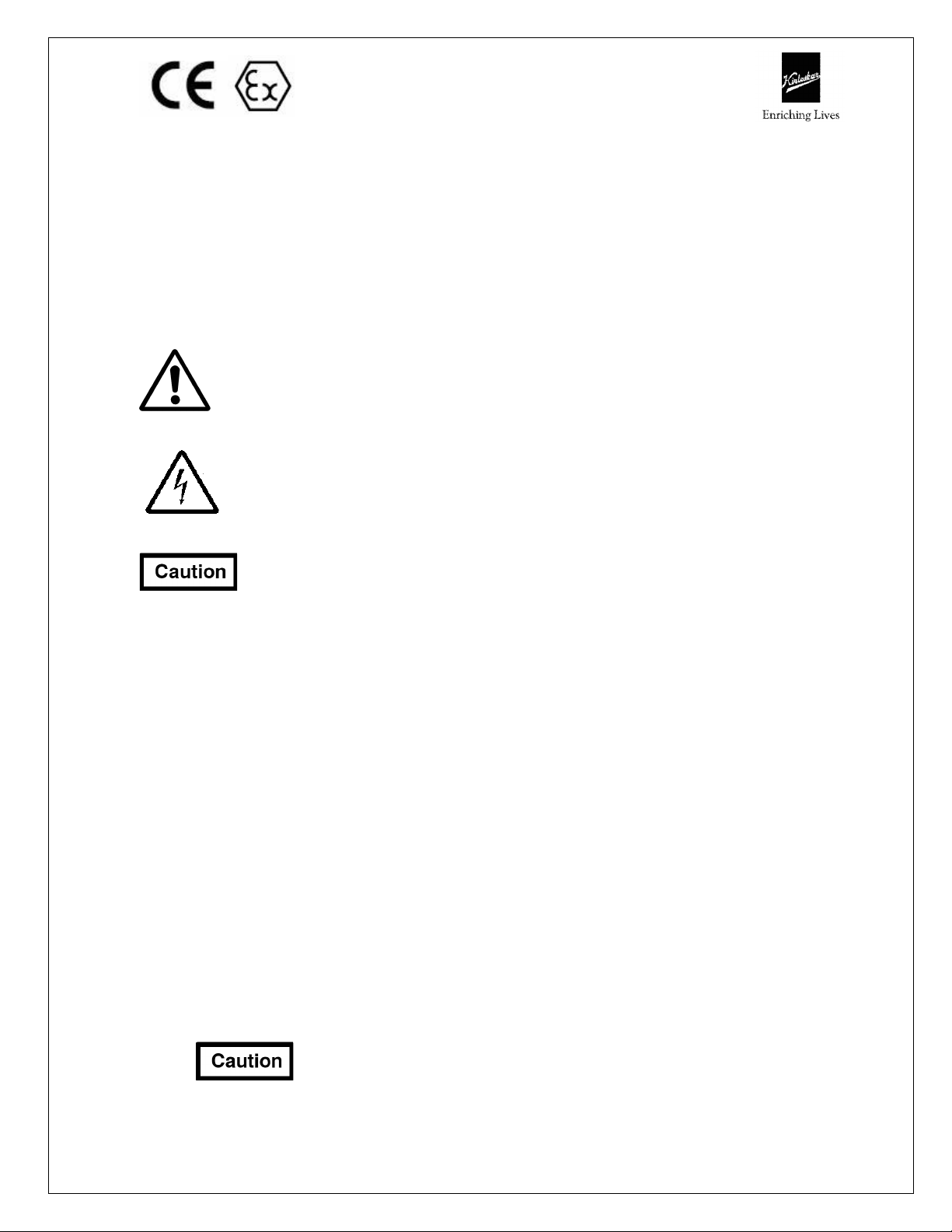
2.1.1 Within the manual, safety instructions are marked with safety symbols.
Hazard.
This symbol refers to general mechanical aspects of safety.
Hazard.
This symbol refers to electrical safety.
This symbol is used to introduce safety instructions whose nonObservance may lead to damage to the machine and its functions.
2.1.2 KBL products are designed for installation in designated areas, which are to
be kept clean and free of obstructions that may restrict safe access to the
controls and maintenance access points.
Pump name plate is fitted to each unit and must not be removed. Loss of
this plate could make identification impossible. This in turn could affect
safety and cause difficulty in obtaining spare parts. Should accidental loss or
damage occur, contact KBL immediately.
2.1.3 Access to the equipment should be restricted to the personnel responsible
for installation, operation and maintenance and they must be trained,
adequately qualified and supplied with the appropriate tools for their
respective tasks.
2.1.4 KBL firmly insists that all personnel responsible for installation, operation and
maintenance of the equipment must read the manual before any work is
done.
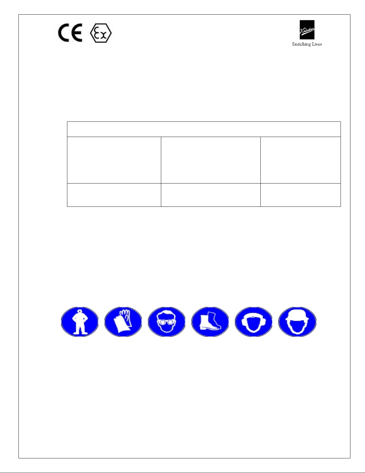
2.1.5 Ear defenders should be worn where the specified equipment noise level
exceeds locally defined safe levels. Safety glasses or goggles should be
worn where working with pressurized systems and hazardous substances.
Other personal protection equipment must be worn where local rules apply.
2.2
could catch on the controls or becomes trapped in the equipment.
DO NOT wear loose or frayed clothing or jewellery, which
IOM/GK(P)/CONICAL ISSUE DATE: 10.11.2015
Page 12 LAST REV. DATE: 01.08.2019
2.3 Operation of the equipment for the application other than for which it is
supplied can increase the risk from hazards. Please consult KBL before
making such change in the application of the equipment.
2.4 Improper installation, operation and maintenance of the product supplied by
KBL could result in injury or death.
2.5
In case of GK(P)CLM pumps which are handling fluid at very
high temperature, the operator should avoid touching the pump in running
condition.
while operating GK(P)CLM pumps meant for High temperatures.
Use safety equipments like hand gloves and safety shoes
2.6 Transport handling and storage instructions:
2.6.1 Transport.
Pumps are dispatched in duly assembled condition. Lubricating oil in the
bearing housing is drained prior to dispatch of pump. Pumps are protected against
corrosion and packed for transport by normal road, rail and sea carriers.
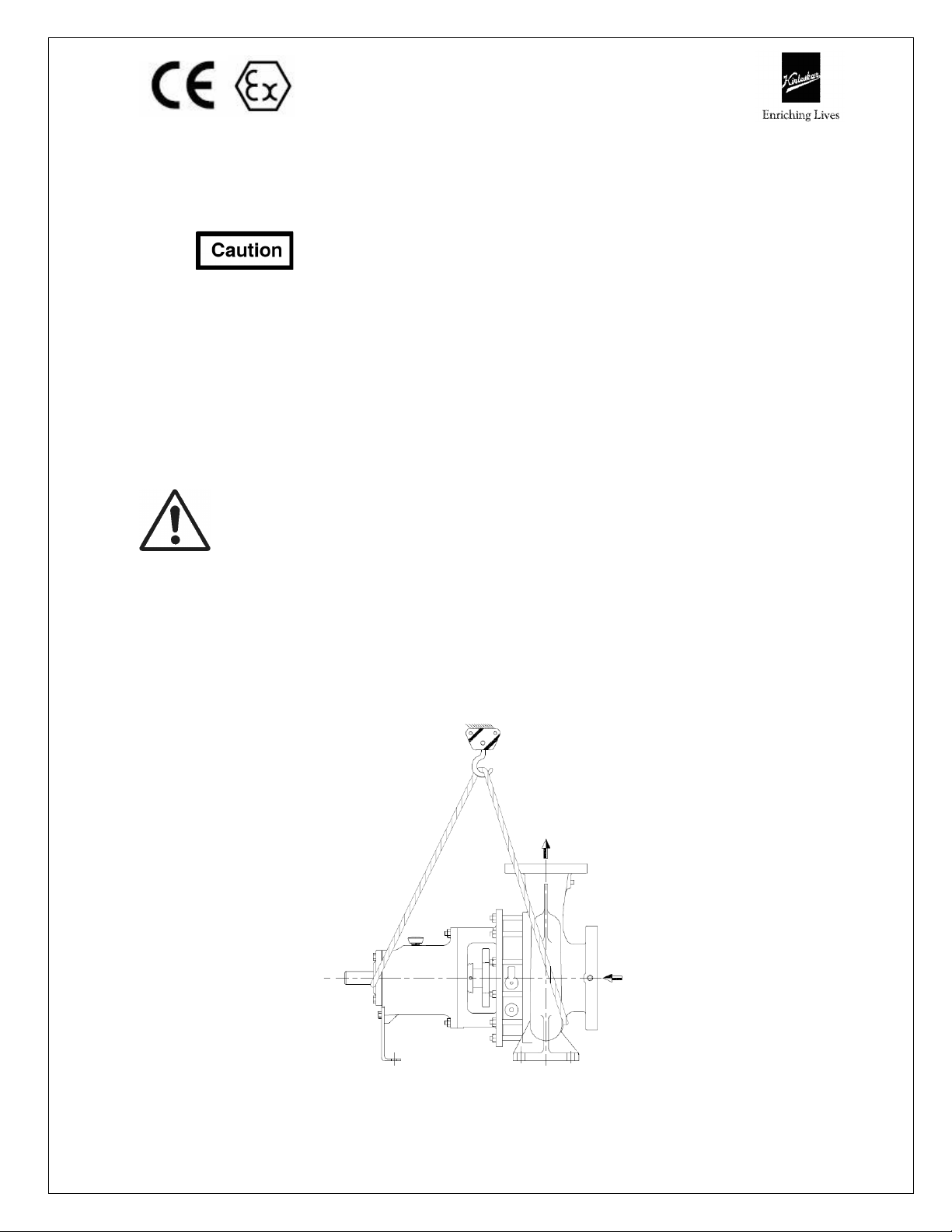
2.6.2 Handling
Crushing hazard
When lifting the pump or pump set, use lifting equipment having a safe working
load rating suitable for the weight specified. Use suitable slings for lifting any pump
not provided with lifting points.
The use of suitable forklift truck and four chain crane sling equipment is
recommended but locally approved equipment rating may be used.
Pump should be slung as shown.
Lifting of bare shaft pump
IOM/GK(P)/CONICAL ISSUE DATE: 10.11.2015
Page 13 LAST REV. DATE: 01.08.2019
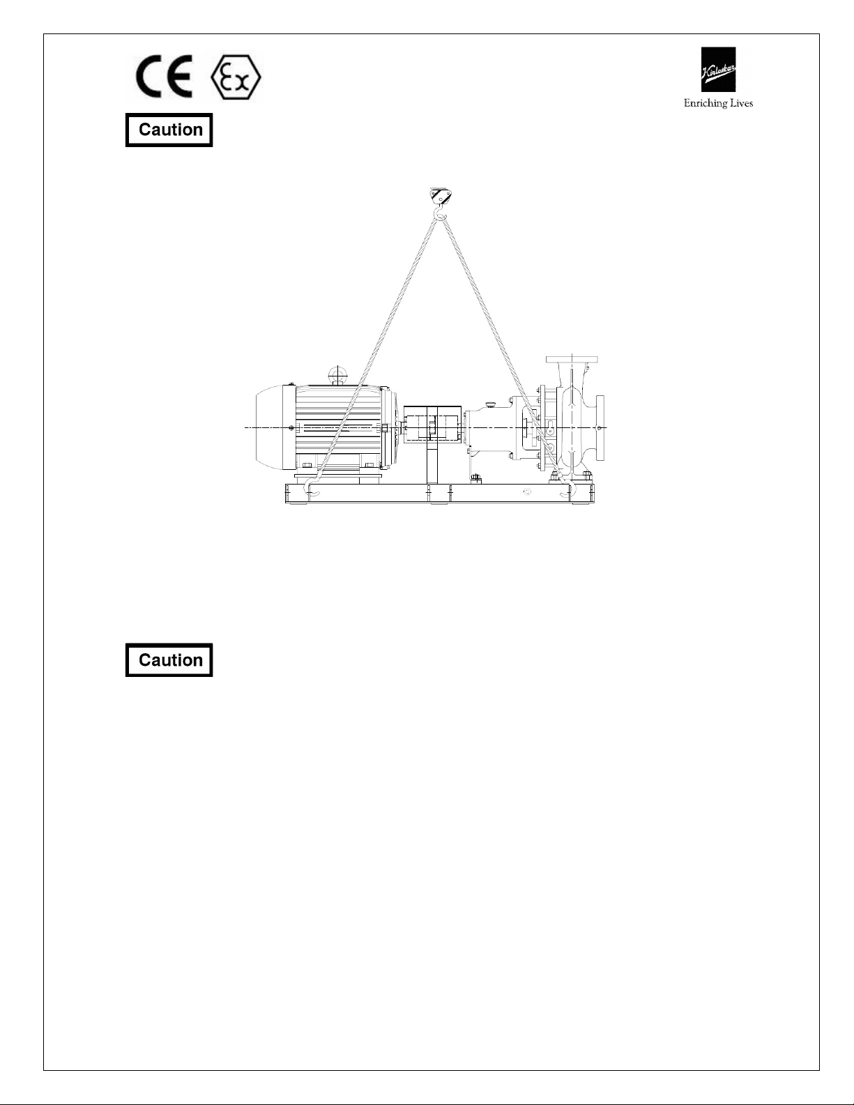
Pump set must be lifted from the lifting holes provided using suitable four chain
lifting equipment.
Lifting of Pump set
2.6.3 Storage.
2.6.3.1 Temporary storage for up to six weeks.
If the pump unit is not to be used immediately it should be stored carefully in a
horizontal position, in a sheltered, dry location.
Additional rust preventive should be applied to all unpainted carbon
steel or cast iron parts and should not be removed until final installation.
2.6.3.2 Long Term Storage.
If the pump is not to be installed and operated soon after arrival, store it in a clean,
dry place, having slow, moderate changes in ambient temperature. Step should be
taken to protect the pump from moisture, dust, dirt, and foreign bodies. It is
recommended that the following precautions to be taken:
a) Ensure that the bearings are packed with the recommended grease, to prevent
moisture from entering around the shaft.
b) Remove the glands, packings and lantern rings from the stuffing box if the pump
is equipped in this manner. If the pump is equipped with mechanical seal,
dismantle and coat the seal with light oil.
c) Ensure that suction and discharge branches of the pump and all other openings
are covered with cardboard, wood or masking tape to prevent foreign objects
entering the pump.
d) If the pump is to be stored where there is no protective covering, it is advisable
to cover the unit with a tarpaulin or other suitable covering.
IOM/GK(P)/CONICAL ISSUE DATE: 10.11.2015
Page 14 LAST REV. DATE: 01.08.2019
e) The pump shaft should be manually rotated periodically to prevent pitting of the
bearing surfaces due to moisture.
Shearing Hazard
DO NOT place fingers or hands etc., into the suction or discharge pipe outlets
and do NOT touch the impeller, if rotated this may cause severe injury. To prevent
ingress of any objects, retain the protection covers or packaging in place until
removal is necessary for installation. If the packaging or suction and discharge
covers are removed for inspection purposes, replace afterwards to protect the
pump and maintain the safety.
Fill the bearing housing with recommended oil to ensure that the shaft and bearings
remain rust free.
2.6.3.3 Exposed or Extreme Conditions Storage.
For exposed storage or extreme variants in atmospheric or environmental
conditions, please refer to KBL for special storage instructions to suit the conditions
acceptable.
3. Equipment schedule:
3.1 INSTALLATION:
3.1.1 For location, preparing foundation, installation, alignment, piping, general
maintenance, trouble shooting, etc., the instructions given in our publication
-’GENERAL INSTRUCTIONS FOR INSTALLATION, OPERATION AND
MAINTENANCE OF KIRLOSKAR CENTRIFUGAL PUMPS’ which is also
printed along with this booklet must be followed very carefully. If the pump
is drawing liquid from the vessel under vacuum, then vacuum equalizing
connection piping must be made as per instruction given in above
publication. The external sealing connection to the pump, if applicable, must
be made after installing and before commissioning the pump. Pump on hot
service must have final coupling alignment made with the unit at its
operating temperature.
3.1.2 Receiving pump
Upon receipt of the pump, a visual check should be made to determine if any
damage occurred during transit or handling. The main items to look for are:
a) Broken or cracked equipment, including base, motor or pump feet and
flanges.
b) Bent shaft.
c) Broken motor end bells, bent eyebolts or damaged boxes of motor.
d) Missing parts.
e) Pump shaft rotates freely.
Parts or accessories are sometimes wrapped individually or fastened to the
equipment. If any damage or losses have been incurred; promptly notify your
IOM/GK(P)/CONICAL ISSUE DATE: 10.11.2015
Page 15 LAST REV. DATE: 01.08.2019
KBL representative, KBL Dealer and the transport company who delivered
the pump.
When unloading pump units, lift equally at four or more points from the
base.
DO NOT LIFT ONLY THE DRIVER OR PUMP.
3.1.3 Preparation
• Before installing the pump, clean the suction and discharge flanges
thoroughly.
• Remove the protective coating from the pump shaft.
• If the pump has been in storage and prepared for storage in the manner
outlined previously, remove all the grease from the bearings. The
bearings should then be flushed with carbon tetrachloride or kerosene
and relubricated. Make sure rust preventives on liquid wetted
components cleaned thoroughly prior to pump put into service. Failing to
this may result into hazardous condition by reaction with pumping media.
3.1.4 Location
• The pump should be installed as near the liquid source as possible, with
the shortest and most direct suction pipe practically. HIS Guidelines for
piping system arrangement should be followed for trouble free long life
service of pump.
• The pump should be installed with sufficient accessibility for inspection
and maintenance. Ample space and head room should be allowed for the
use of an overhead crane or hoist sufficiently strong to lift the unit.
• Make sure there is a suitable power source available for the pump driver.
If motor driven, electrical characteristics should be identical to those
shown on motor data / name plate.
3.1.5 Foundation
• The foundation should be strong enough to reduce vibrations and rigid
enough to avoid any twisting or misalignment.
• The foundation should be poured without interruptions to within 20 to
40 mm of the finished height. The top surface of the foundation should
be well scored and glued before the concrete sets. This provides a
bonding surface for the grout. Foundation bolts should be set in concrete
as shown in Foundation plan / General Arrangement drawing. Allow
enough bolt length for grout, shims, lower base plate flange, nuts and
washers. The foundation should be allowed to cure for several days
before the base plate is shimmed and grouted.
3.1.6 Base plate setting
• Use blocks and shims under base for support at foundation bolts and
midway between bolts, to position base approximately 25 mm above the
concrete foundation with studs extending through hole in the base plate.
IOM/GK(P)/CONICAL ISSUE DATE: 10.11.2015
Page 16 LAST REV. DATE: 01.08.2019

• By adding or removing shims under the base, level the pump shaft and
flanges. The base plate does not have to be leveled. Draw foundation
bolt nuts tight against base plate and observe pump and motor shafts or
coupling hubs for alignment.
• Check to make sure the piping can be aligned to pump flanges without
placing pipe strain on either flange.
• Grout base plate in completely and allow grout to dry thoroughly before
attaching piping to pump (24 hours is sufficient time with approved
grouting procedure).
3.1.7 Grouting procedure
Grout compensates for uneven foundation, distributes weight of unit and
prevents shifting. Use an approved, non-shrinking grout as follows, after
setting and leveling unit
• Build strong form around foundation to content grout.
• Soak top of concrete foundation thoroughly, then remove surface water.
• Base plate should be completely filled with grout and, if necessary, drill
vent holes to remove trapped air.
• After grout has thoroughly hardened, check the foundation bolts and
tighten if necessary.
• Check the alignment after the foundation bolts are tightened.
• Approximately 14 days after the grout has been poured or when the
Grout has thoroughly dried, apply an oil base paint to the exposed edges
of the grout to prevent from air and moisture coming in contact with the
grout.
3.1.8 Suction and Discharge Piping
When installing the pump piping, make sure to observe the following
precautions:
• Piping should always run to the pump. Do not move pump to pipe. This
could make final alignment impossible.
• Both suction and discharge piping should be supported independently and
close to pump so that no strain is transmitted to the pump when the
flange bolts are tightened.
• Use pipe hangers or other supports at necessary intervals to provide
support. When expansion joints are used in the piping system, they must
be installed beyond the piping supports close to the pump.
• It is advisable to increase the size of both suction and discharge pipes at
the pump connection to decrease the loss of head from friction.
• Install piping as straight as possible, avoiding unnecessary bends. Where
necessary, use long sweep 90 degrees bend to decrease friction losses.
• Make sure that all piping joints are air tight. Provide pipe expansions
bellows when hot fluids are to be pumped. Where reducers are used,
IOM/GK(P)/CONICAL ISSUE DATE: 10.11.2015
Page 17 LAST REV. DATE: 01.08.2019
eccentric reducers are to be fitted in suction lines and straight taper
reducers in discharge and vertical lines.
• Misuse of reducers may cause the formation of air pockets in the pipe
and thus preventing the correct operation of the pump.
• The suction pipe should be as short & direct as possible. Where suction
lift is not very high, it is advisable to use a foot valve. Horizontal suction
line must have a gradual rise to the pump.
• The discharge pipe is usually preceded by a non-return valve or check
valve and a discharge gate valve. The check valve is to protect the pump
from excessive back pressure and reverse rotation of the unit and to
prevent back flow into the pump in case of stoppage or failure of the
driver. The discharge valve is used in priming, starting and when shutting
down the pump.
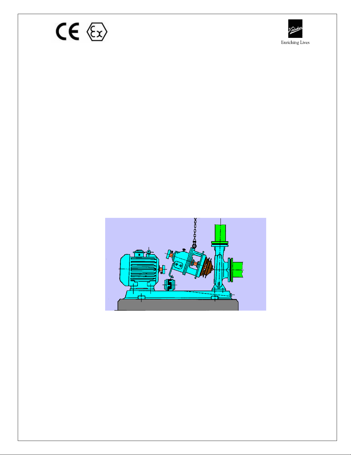
3.2 MOUNTING AND ALIGNMENT
A spacer type flexible coupling is used to connect pump shaft to the driver.
By using spacer type of coupling, the complete rotating unit can be removed
from the volute without removing pump casing or rotor and without
disconnecting piping connections. This also avoids any realignment of pump
and motor after re-assembly of rotating unit. However, other types of
coupling can be supplied against request.
Back pull out assembly of GK(P) pump
3.2.1 ALIGNMENT
The pump driver, if supplied, is correctly aligned on its base plate at the
factory. A certain amount of deformation of the base plate is possible during
transit and it is therefore essential to check alignment, prior to final grouting.
A flexible coupling will only compensate for small amount of misalignment
and should not be used to compensate for excessive misalignment of the
pump and driver shafts.
Inaccurate alignment results in vibration and excessive wear on the bearings,
sleeve or shaft and wear rings.
IOM/GK(P)/CONICAL ISSUE DATE: 10.11.2015
Page 18 LAST REV. DATE: 01.08.2019
ALWAYS REMEMBER “A FLEXIBLE COUPLING IS NOT A UNIVERSAL
JOINT”
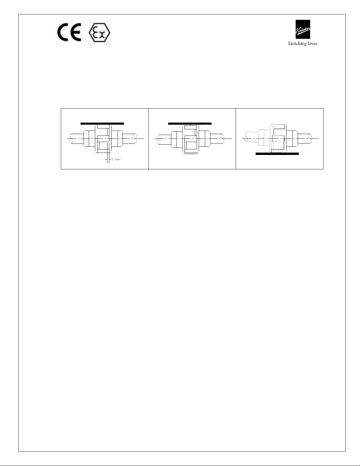
Correct alignment is essential for the smooth operation of the pump. There
are two types of misalignment between the pump shaft and the drive shaft,
which are:
1) Angular misalignment – shaft with axis concentric, but not parallel.
Maximum allowable misalignment is 1°.
STEEL STRAIGHT EDGE
CORRECT
Checking coupling alignment with straight edge
STEEL STRAIGHT EDGE
INCORRECT PARALLEL
MISALIGNMENT
2) Parallel misalignment – shaft with axis parallel, but not concentric.
Maximum allowable misalignment is 0.1 mm.
This misalignment is checked by using a straight edge as shown in Figure
given above. Coupling alignment can be checked with dial gauge Indicator.
Alignment should be performed after the base plate has been properly set
and grout has dried thoroughly according to instructions. Final alignment
should be made by shimming under driver side only.
Alignment should be made at operating temperatures.
After final alignment, it is necessary to dowel pump and driver feet to the
baseplate.
FACTORS THAT MAY DISTURB ALIGNMENT
The unit should be periodically checked for alignment. If the unit does not
stay in line after being properly installed, the following are possible reasons:
a) Setting, Seasoning of the foundation.
b) Pipe strains, distorting or shifting of the machines.
c) Wear of the bearings.
3.2.1.1 Before commissioning the pump set, please ensure:
A) The pipe connections are flushed and tightened properly.
B) Alignment is proper.
C) Auxiliary piping connections such as sealing connections, cooling
connections, etc., are made. Details of sealing liquid are given in our
supply order.
Please refer to Figure given below for plugs and piping connections.
INCORRECT ANGULAR
MISALIGNMENT
STEEL STRAIGHT EDGE
IOM/GK(P)/CONICAL ISSUE DATE: 10.11.2015
Page 19 LAST REV. DATE: 01.08.2019
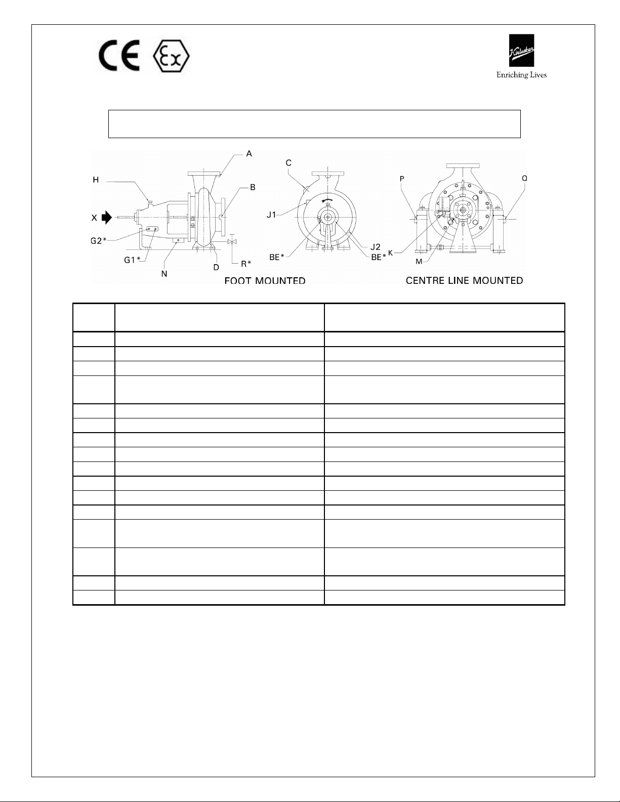
H Air b
reather cap.
On beari
ng housing top.
J1 - St. box jacket he
ating steam inlet.
Casing cover top left.
Code Description Location of connection when viewed from
A Gauge connection discharge side. On pump discharge flange.
B Gauge connection suction side. On suction flange right.
C Flushing line connection. On casing top left.
D Pump casing drain. On pump casing bottom side towards
G1* Bearing housing cooling water inlet. On bearing housing right.
G2* Bearing housing cooling water outlet. On bearing housing right.
GK(P) PUMPS – TAPPINGS CONNECTIONS CHART
driving end
suction.
J2 - St. box jacket heating steam outlet. Casing cover bottom right.
K Constant level oiler. On bearing housing left.
M Bearing housing oil drain. On bearing housing left.
N* Drip pan drain. On bearing housing bottom right.
P Pad cooling water inlet for centre line
mounted pumps.
Q
Pad cooling water outlet for centre
line mounted pumps.
On pad for centre line mounted pump
casing.
On pad for centre line mounted pump
casing.
R* For drain cock and piping. On pump casing bottom.
BE* For bulls eye indicator. On bearing housing both sides.
*
This special provision on request / application requirement only.
– Will be applicable only for jacketed pump.
IOM/GK(P)/CONICAL ISSUE DATE: 10.11.2015
Page 20 LAST REV. DATE: 01.08.2019
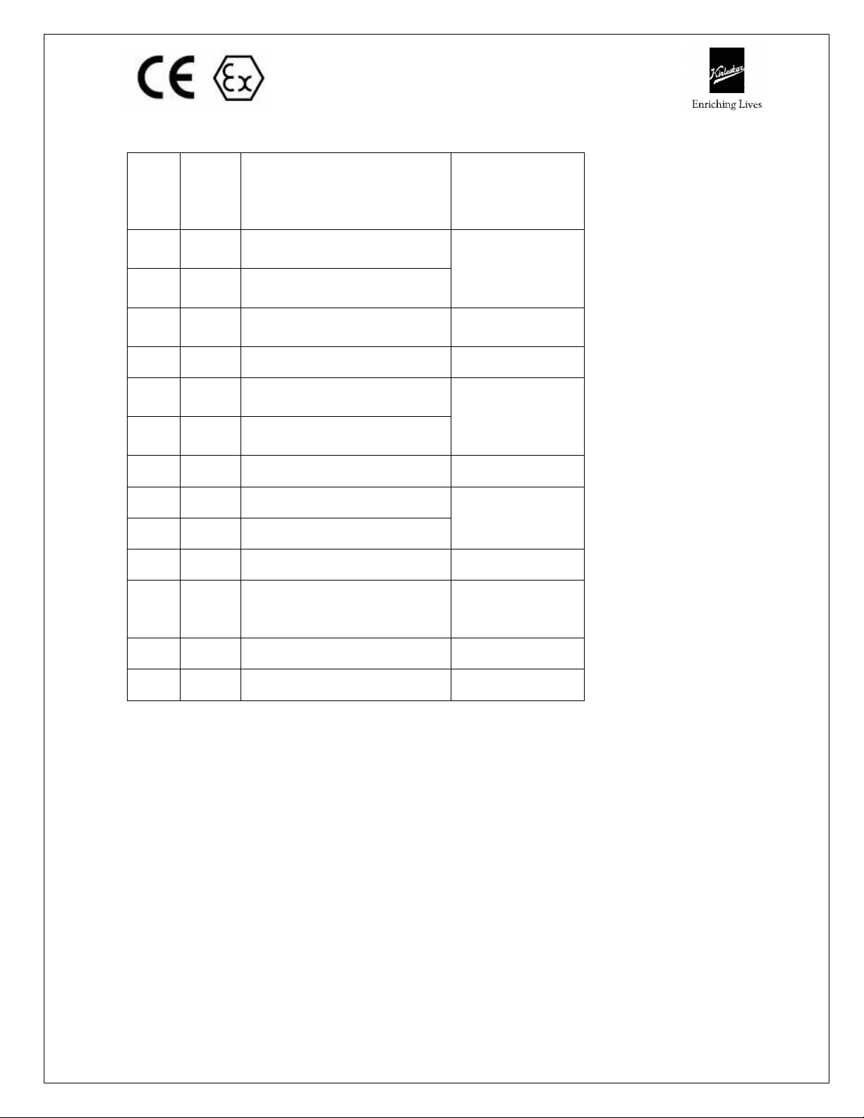
Tapping size details for GK(P) pump:
SR.
NO.
CODE
DESCRIPTION
OF
PIPE
CONN
1 A
2 B
3 C
Gauge connection
discharge side.
Suction Gauge / Vacuum
equalising connection.
Flushing/Sealing conn.
from pump casing.
CONNECTION
4 D Pump casing drain. 1/2
SIZE OF
1/4
1/4
5 G1*
6 G2*
Bearing housing cooling
water inlet.
Bearing housing cooling
water outlet.
1/2
7 H Air breather cap. 20 mm hole
8 K Constant level oiler.
1/4 BSP
9 M Bearing housing oil drain.
10 N* Drip pan drain. 1/2
11
P
Q
Pad cooling water for
centre line mounted pump
inlet & outlet.
1
12 R* Drain cock and piping. 1/2
13 BE* Bulls eye indicator. 1/2 BSP
Notes:
All tappings are in inches and location of connections are specified looking from
arrow “X”.
* This special provision on request / application requirement only and at extra cost.
All connections are NPT except specified.
3.2.1.2 CONSTANT LEVEL OILER
GK(P) pumps are oil lubricated as standard scope of supply. Pump is
provided with constant level oiler.
Procedure for standard KBL make constant level oiler is as given below.
For other than KBL make refer respective make work instruction supplied.
Fix the constant level oiler and fill the oil. Procedure for fitting the
constant level oiler and the method of filling oil is given below.
Constant level oiler has plastic container in Aluminium body as a
standard supply. Connection stem is ¼ inch BSP tapped and its capacity
IOM/GK(P)/CONICAL ISSUE DATE: 10.11.2015
Page 21 LAST REV. DATE: 01.08.2019
 Loading...