

KIRLOSKAR GK32/13B, GK32/13A, GK40/26B, GK65/32B, GK50/26A Instruction On Installation, Operation And Maintenance
...
INSTRUCTIONS ON
INSTALLATION,
OPERATION AND
MAINTENANCE FOR
KIRLOSKAR PUMP
TYPE ‘GK’
KIRLOSKAR BROTHERS LIMITED
REGD. AND HEAD OFFICE UDYOG BHAVAN, TILAK ROAD PUNE-411002
1 IOM/GK/SEP19/00
WARRANTY
We warrant that the pump supplied from us is free from
defective material and faulty workmanship. This warranty holds
good for a period of 12 months from the date of commissioning
the equipment or 18 months from the date of dispatch from our
factory, whichever is earlier. Our liability in respect of any
complaint is limited to replacing part/parts free of charge exworks or repairs of the defective part/parts only to the extent
that such replacement/repairs are attributable or arise solely from
faulty workmanship or defective material.
This warranty holds good only for the products manufactured by us.
KIRLOSKAR BROTHERS LIMITED
2 IOM/GK/SEP19/00

Sr. No. Description
Page No.
1.0 General 04
2.0 Safety Instructions 05
3.0 Equipment Schedule 09
4.0 Operation 12
5.0 Maintenance Manual 14
5.1 Maintenance EHS instructions 14
5.2 General maintenance documents 14
5.3 Overhauling 14
5.3.1 Dismantling 15
5.3.2 Reassembly 18
5.4 Maintenance Tools required 19
5.5 Preventive Maintenance 19
5.5.1 Daily Checks 19
5.5.2 Periodical Checks 19
5.5.3 Annual Checks 20
5.5.4 Mechanical Seal in Pumps 20
5.6 Corrective Maintenance 21
6.0 Technical Data 21
6.1 Direction of Rotation 21
6.2 Bearing Details 21
6.3 Bearing Lubrication 21
6.4.1 Stuffing Box Sealing 22
6.4.2
6.4.3 Stuffing Box Packing & Lantern Ring 22
6.4.4 Gaskets, O-rings & Wear Ring details 23
6.4.5 Interchangeability Chart of Components 26
6.4.6 Recommended Spare Parts 29
7.0 Part Description and Sectional
8.0 Exploded View 36
9.0 General Outline Dimensions 37
10.0 Cut section View 39
Table of contents
Stuffing Box packing specification 22
Drawings 30
3 IOM/GK/SEP19/00
GK32/13
A GK40/26B
GK65/32B
GK32/13B
GK50/26A
GK80/32B
GK32/16
GK50/32A
GK80/40B
GK32/20A
GK65/16B
GK100/26B
GK32/20B
GK65/20B
GK100/32B
GK40/13
GK65/26A
GK100/40A
GK40/
16 GK65/26B
GK100/40B
GK40/20A
GK80/16A
GK12
5/26A
GK40/20B
GK80/20A
GK125/32A
GK50/13
GK80/26A
GK125/32B
GK50/16A
GK100/20A
GK50/20A
GK65/13A
1.0 GENERAL:
1.1 ‘KIRLOSKAR’ make GK series pumps are of back pull out design which enables
to remove the rotating unit of pump for inspection and repairs without
disturbing suction and delivery pipe connections.
1.2 The booklet covers instructions for installation, operation & maintenance of
following models of GK Pumps:
GK
UNIT – 30
Applications:
GK
UNIT – 40
GK
UNIT – 50
GK pumps are mainly used for clean and clear liquids which are free from
suspended solids/particles. Few of the applications are as below:
Water supply, Sprinkling, Air conditioning, Industrial water, Swimming pool water,
Hot water, Fire fighting, Irrigation, Drinking water/Potable water, Cooling water,
Condensate, Clear juice.
1.3 Nameplate information:
Every pump has the following nameplate fitted to bearing housing
(2400000) provided with necessary identification of the pump and its
specific hydraulic characteristics.
Loss of this plate could make
affect safety and cause difficulty in obtaining spare parts.
loss or damage if occur, contact KBL immediately.
The nameplate must not be removed.
identification impossible. This in turn could
Such accidental
4 IOM/GK/SEP19/00

1.4 Pumps when properly installed & given due care in operation & maintenance
should operate satisfactorily for a long period.
1.5 When the pump is received, sometime before the actual use of pump, it should
be inspected & located in dry place. The shaft should be rotated once in a
month to prevent pitting of bearing surfaces.
2.0
2.1 General Information
2.2.1 Within the manual, safety instructions are marked with safety symbols.
Safety Instructions:
Before performing any actions detailed within this instruction, the site Health
and Safety instructions and the instructions in this document shall be read and
fully understood.
Whenever the equipment is operated, maintained or used in any way,
the procedures detailed within these instructions shall be followed. The
pump supplied by Kirloskar Brothers Limited (KBL) has been designed
with safety in mind; where hazards cannot be eliminated, the risk has
been minimized by the use of guards and other design features. Some
hazards cannot be guarded against and the instructions below MUST BE
COMPLIED WITH for safe operation. These instructions cannot cover all
circumstances. It is the responsibility of the user of the equipment for
maintaining safe working practices at all times. The pumps are supplied with
stickers for hazard, caution & safety wherever these are applicable.
Hazard.
This symbol refers to general mechanical aspects of safety.
Hazard.
This symbol refers to electrical safety.
5 IOM/GK/SEP19/00
CA
CACA
CA
UTION
UTIONUTION
UTION
This symbol is used to introduce safety instructions whose
CAUTION
nonobservance may lead to damage to the machine and its
functions.
2.1.2 KBL products are designed for installation in designated areas, which are to be
kept clean and free of obstructions that may restrict safe access to the controls
and maintenance access points.
2.1.3 Access to the equipment should be restricted to the personnel responsible for
installation, operation and maintenance and they must be qualified, adequately
trained and supplied with the appropriate tools for their respective tasks.
2.1.4 This product must be serviced by qualified personnel who are familiar with
the design and operation of this product and the system with the
essential safety aspects involved.
2.1.5 KBL firmly insists that all personnel responsible for installation, operation and
maintenance of the equipment must read the manual before any work is done.
2.1.6 Our guarantee
maintenance and repairs of this pump are carried out in accordance
will be valid only if the installation, operation,
with these
instructions. The plant operator is to make sure that the contents of these
instructions are fully understood by the operating
personnel. During
operation, periodic inspections should be made to assure safe operation
under the prevailing conditions.
2.1.7 Ear defenders should be worn where the specified equipment noise level
exceeds locally defined safe levels. Safety glasses or goggles should be
worn where working with pressurized systems and hazardous substances.
Other personal protection equipment must be worn where local rules apply.
2.1.8 Any modification may be made to the product only after consultation
with the manufacturer. Using spare parts and accessories authorized by
the manufacturer is a relevant safety aspect. Only genuine spare parts
which are in accordance with the original delivery (in the parts list) are to
be used.
2.2
DO NOT
wear loose or frayed clothing or jewellery, which
could catch on the controls or become trapped in the
equipment.
2.3 Operation of the equipment for the application other than for which it is
supplied can increase the risk from hazards. Please consult KBL before making
such change in the application of the equipment.
2.4 Improper installation, operation and maintenance of the product supplied by KBL
could result in injury or death.
2.5 Within the manual, safety instructions are marked with safety symbols.
6 IOM/GK/SEP19/00

2.6
Transport Handling and Storage Instructions:
2.6.1 Transport
Pumps are dispatched in duly assembled condition. Lubricating oil in the
bearing housing is drained prior to dispatch of pump. Pumps are protected
against corrosion and packed for transport by normal road, rail and sea
carriers.
2.6.2 Handling
Crushing Hazard.
When lifting the pump or pump set, use lifting equipment having a safe working load
rating suitable for the weight specified. Use suitable slings for lifting the pump which
is not provided with lifting points.
The use of suitable forklift truck and four chain crane sling equipment is recommended
but locally approved equipment rating may be used.Pump should be slung as shown.
Pump set must be lifted from the lifting holes provided using suitable four chain lifting
equipment.
7 IOM/GK/SEP19/00
2.6.3
Storage:
2.6.3.1 Temporary Storage for up to six weeks.
If the pump unit is not to be used immediately it should be stored carefully in a
horizontal position, in a sheltered, dry location. Additional rust preventive
should be applied to all unpainted carbon steel or cast-iron parts and should not
be removed until final installation.
2.6.3.2 Long Term
If the pump is not to be installed and operated soon after arrival, store it in a
clean, dry place, having slow, moderate changes in ambient temperature.
Step should be taken to protect the pump from moisture,
foreign bodies. It is recommended that the following precautions to be
taken:
a)
Ensure that the bearings are packed with the recommended grease, to
prevent moisture from entering around the shaft.
b)
Remove the glands, packings and lantern rings from the stuffing box
if the pump is equipped in this manner. If the pump is equipped with
mechanical seal, dismantle and coat the seal with light oil.
c)
Ensure that suction and discharge branches of the pump and all other
openings are covered with cardboard, wood or masking tape to
prevent foreign objects entering the pump.
d)
If the pump is to be stored where there is no protective covering, it
is advisable to cover the unit with a tarpaulin or other suitable
covering.
e)
The pump shaft should be manually rotated periodically to prevent
pitting of the bearing surfaces due to moisture.
Storage
.
dust, dirt, and
Shearing Hazard.
Do NOT place fingers or hands, etc., into the suction or discharge pipe outlets
and do NOT touch impeller, if rotated this may cause severe injury.
Fill the bearing housing with recommended grease to ensure that the shaft and
bearings remain rust free.
2.6.3.3 Exposed or Extreme Conditions Storage.
For exposed storage or extreme variants in atmospheric or environmental
conditions, please refer to KBL for special storage instructions to suit the
conditions acceptable.
2.7 Environmental safety
Always keep the station clean to avoid and/or discover emissions.
Waste and emissions regulations
Observe these safety regulations regarding waste and emissions:
• Appropriately dispose of all waste.
8 IOM/GK/SEP19/00
:
• Handle and dispose of the processed liquid in compliance with applicable
environmental regulations.
• Clean up all spills in accordance with safety and environmental procedures.
• Report all environmental emissions to the appropriate authorities.
Electrical installation
For electrical installation recycling requirements, consult your local electric utility.
Recycling guidelines
Always follow local laws and regulations regarding recycling.
3.0
Equipment Schedule:
3.1 Installation:
3.1.1 For location, preparing foundation, installation, alignment, piping, general
maintenance, trouble shooting, etc., the instructions given in our publication ’GENERAL INSTRUCTIONS FOR INSTALLATION, OPERATION AND
MAINTENANCE OF KIRLOSKAR CENTRIFUGAL PUMPS’ which is also printed
along this booklet must be followed very carefully.
3.1.2 MOUNTING AND ALIGNMENT
A spacer type flexible coupling is used to connect pump shaft to the driver. By
using spacer type of coupling, the complete rotating unit can be removed from
the volute without removing pump casing or rotor and without disconnecting
piping connections. This also avoids any realignment of pump and motor after
re-assembly of rotating unit.
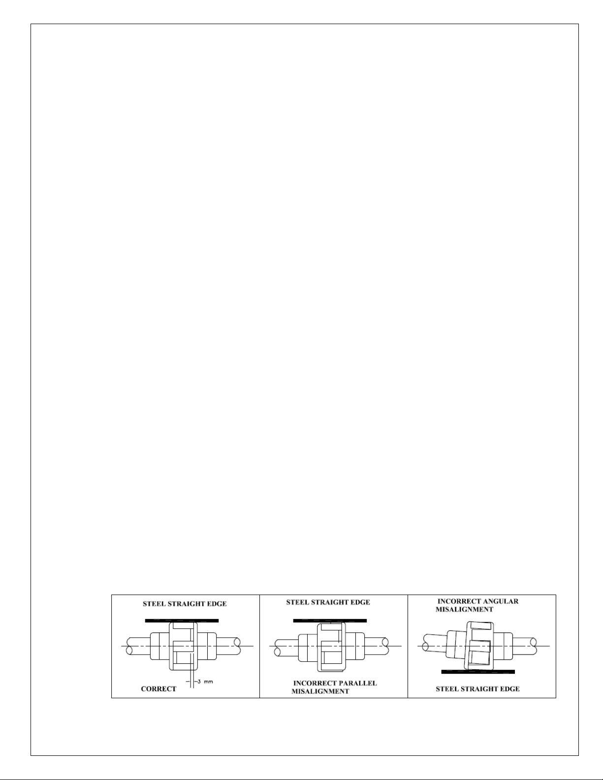
3.1.3 ALIGNMENT
ALWAYS REMEMBER “A FLEXIBLE COUPLING IS NOT A UNIVERSAL
JOINT”.
Correct alignment is essential for the smooth operation of the pump. There
are two types of misalignment between the pump shaft and the drive shaft,
which are:
1) Angular misalignment – Shaft with axis concentric, but not parallel.
Maximum allowable misalignment is 1°.
2) Parallel misalignment – Shaft with axis parallel, but not concentric.
9 IOM/GK/SEP19/00

This misalignment is checked by using a straight edge as shown in figure
given above. Before commissioning the pump set, please ensure:
3) The pipe connections are flushed and tightened properly.
4) Alignment is proper.
5) Auxiliary piping connections such as sealing connections, cooling
connections, etc., are made. Details of sealing liquid are given in our supply
order.
FACTORS THAT MAY DISTURB ALIGNMENT
The unit should be periodically checked for alignment. If the unit does not
stay in line after being properly installed, the following are possible reasons:
a) Setting, Seasoning of the foundation.
b) Pipe strains, distorting or shifting of the machines.
c) Wear of the bearings.
3.1.4 Before commissioning the pump set, please ensure:
A. The pipe connections are flushed and tightened properly.
B. Alignment is proper.
C. Auxiliary piping connections such as sealing connections, cooling connections,
etc., are made.
D. External connection to the pump if applicable, must be made after installation
and before commissioning of pump.
10 IOM/GK/SEP19/00

Following tapings are provided on Pump Casing, Suction Cover and bearing
housing:
11 IOM/GK/SEP19/00

4.0 OPERATION:
4.1 EQUIPMENT DESCRIPTION:
End suction centrifugal pump type GK is from KBL manufactured pump series
which dimensionally conforms to ISO 5199 or EN 22858. The mechanical
assembly comprises a rigid shaft, supported on deep groove ball bearings with a
double shrouded impeller mounted in a removable bearing housing assembly.
This is attached to an end suction volute casing fitted with wear rings and back
vanes. The bearing housing, shaft and impeller assembly can be withdrawn
from the volute for maintenance without disconnection of pipe work.
The discharge branch is positioned vertically upwards while suction branch is
horizontal and is at 90° to discharge nozzle. An additional mounting foot is
fitted at the outer bearing position for stability.
The complete assembly is of rigid construction, being intended for mounting on
suitable base plate with electric motor. A suitable coupling is provided to
transmit the rotational drive between pump and motor. A spacer coupling must
be used to allow the removal of the pump rotating assembly without
disconnecting suction pipe, discharge pipe and motor.
A mechanical seal is used to seal the leakage of pumped liquid across the
shaft. Mechanical seal is optional supply.
4.2 EQUIPMENT OPERATION:
4.2.1 Before starting the pump check the following:
1) The pump rotates freely by hand.
2) Fill in the grease for bearing, if not done earlier. The bearings are packed with
grease initially at the factory. However, if the pump is stored for a longer time it
is necessary to refill the grease in bearings.
3) The direction of rotation of driver. It should correspond to the direction of
rotation of pump.
4) The pump casing and the suction pipeline is fully primed with the liquid.
5) Valve on delivery side is closed.
6) The cock for pressure gauge connection is closed.
4.2.2 Starting the pump.
1) Start the pump. Let the prime mover pickup its full speed.
2) Open the valve on delivery line gradually.
3) Regulate the required flow by adjusting the delivery valve.
4) Open the cock for pressure gauge connection.
4.2.3 During running the pump check the following things and regulate if needed.
1) The pump is running smooth.
2) The flow of sealing liquid [if external liquid is provided for sealing purpose] is
uninterrupted.
3) Leakage through stuffing box is normal. There should be 60-80 drops per
minute.
12 IOM/GK/SEP19/00
4) The bearings are not getting abnormally hot.
5) Head and capacity developed by the pump is as specified.
6) Power consumption is within limit.
7) Ensure that there is no mechanical friction in the pipe.
8) Stop the pump immediately, if any defects are detected. Do not start the pump
unless the defects are rectified.
4.2.4 During stopping the pump
1) Close the valve on the delivery line.
2) Stop the motor.
3) Close the cooling water and sealing liquid connections.
4) If the pump is not required to be operated for a long time, drain the casing
completely. If the pump is required to be stored for a long time, the bearing
housing should be dried internally with hot air and should be flushed with
moisture free protective such as light oil or kerosene.
Be aware of the hazards relating to the pumped fluid, especially the danger from
inhalation of noxious and toxic gases, skin and eye contact or penetration.
Electric Shock and Accidental Starting Hazard:
Isolate the equipment before any maintenance work is done. Switch off the
mains supply, remove fuses, apply lockouts where applicable and affix suitable
isolation warning signs to prevent inadvertent re-connection.
In order to avoid the possibility of maintenance personnel inhaling dangerous
fumes or vapours, it is recommended that maintenance work be carried out
away from the pump location by removal of the rotating unit assembly to a
suitable maintenance area.
Failing to follow right shop practices during equipment operation will result
into failure of product & in turn product warranty gets void.
13 IOM/GK/SEP19/00
5.0 MAINTENANCE MANUAL:
5.1 MAINTENANCE EHS INSTRUCTIONS:
Following hazards may arise during maintenance work.
Fluid Pressure Jet Hazards.
Check and ensure that the pump operates at below the maximum
Working Pressure specified.
Before attempting any maintenance on a pump,
to work on.
purge away any
operator should carry
before starting work. To avoid
wear protective clothing as
The pump must be flushed thoroughly with suitable cleaner to
of the product left in the pump components. The plant
this out and a certificate of cleanliness obtained
any risk to health it is also advisable to
recommended by the site safety officer,
especially when removing old packing that may be contaminated.
5.2 GENERAL MAINTENANCE DOCUMENTS
Maintenance documents:
a) Pump Sectional assembly drawing with part list
b) Pump Outline dimension drawing
c) Mechanical seal assembly / GA drawing
d) Foundation plan drawing
e) Pump data sheet
Specific Maintenance data:
5.3 Overhauling:
With normal daily operating spell, the pump will be due for overhaul after
about 5000 working hours. This work should be done by skilled personnel.
Procedure for dismantling and re-assembly
While dismantling and re-assembling, the cross-sectional assembly drawing and
specification part list should be referred.
ensure that the unit is safe
5.3.1 DISMANTLING
Follow the following simple steps to dismantle the pump.
5.3.1.1 Isolate power supply to motor.
5.3.1.2 Shut off valves controlling flow to and from the pump.
5.3.1.3 Drain the liquid from pump by removing the drain plug or open the pump
casing drain cock.
5.3.1.4 We recommend matching the punch mark of the coupling halves.
14 IOM/GK/SEP19/00
5.3.1.5 In case of the pumps with spacer type flexible couplings, disconnect coupling
(pump half and motor half) from the coupling spacer and remove coupling
spacer. In case of ordinary flexible couplings, remove the motor from the
base.
5.3.1.6 Remove the support foot (25100) hold down bolts.
5.3.1.7 Adjust string or chain tension to support the weight of the back pull out
assembly.
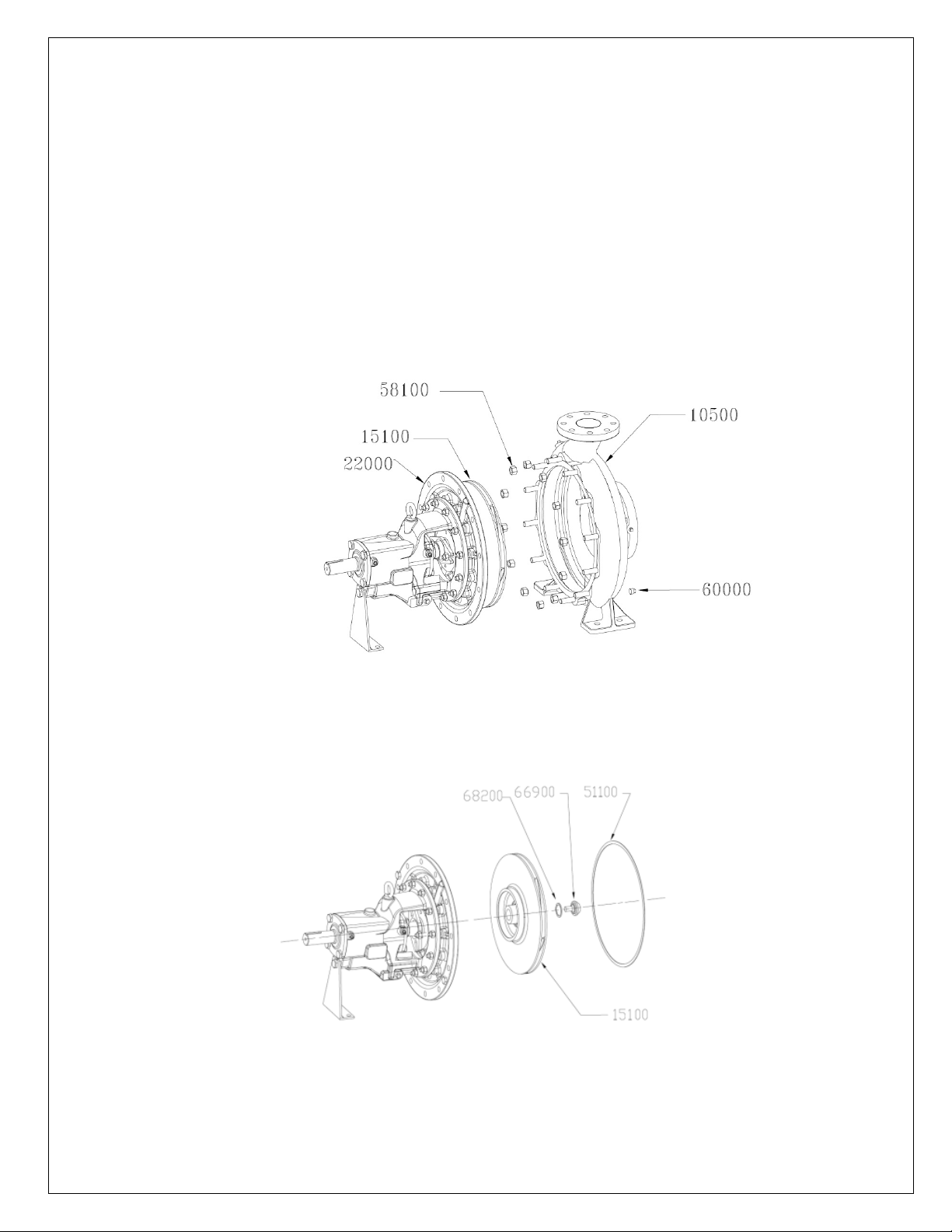
5.3.1.8 Remove the hexagonal nuts (58100) from casing stud holding the casing
cover (22000) to pump casing (10500).
5.3.1.9 Screw the release bolts provided in casing cover. Turn bolts evenly through a
quarter turn at both sides.
5.3.1.10 Slightly pull out the driving unit till impeller (15100) clears the pump casing
(10500).
5.3.1.11 Place this rotating unit on a table or clear place for further dismantling.
5.3.1.12 Remove casing gasket (51100).
5.3.1.13 Unscrew the impeller screw (66900) & remove impeller screw gasket
(51500).
5.3.1.14 Take out the impeller (15100) from pump shaft (18000).
15 IOM/GK/SEP19/00
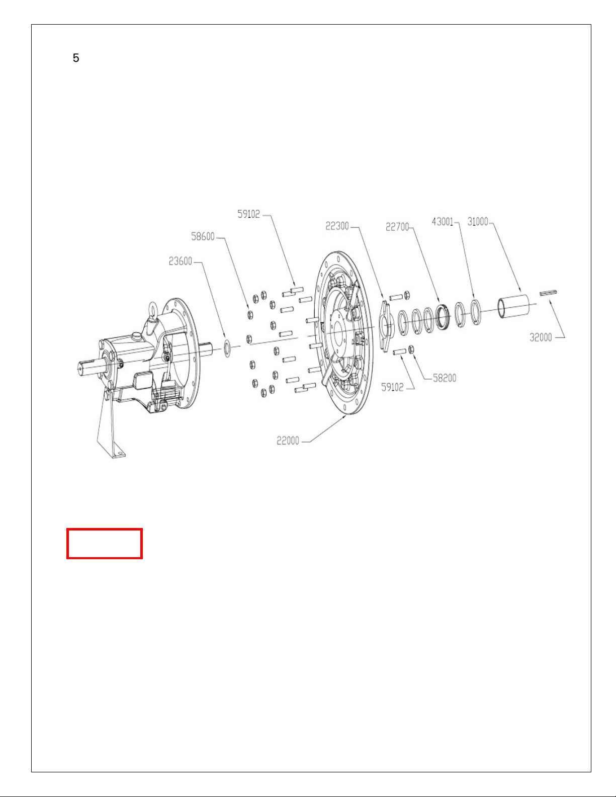
5.3.1.15 Removal of stuffing box with gland packing:
For this, following steps should be taken: Remove the gland (22900) by
taking out bolts used for clamping of the gland. Take out the casing cover
(22000) along with gland packing (43000) and lantern ring (22700).
1) Remove the gland packing rings (43000) and lantern ring (22700).
2) Remove the shaft sleeve (31000) with ‘O’ring (52500).
3) Remove the liquid deflector (23600).
5.3.1.16 Remove the nuts holding the pump casing/casing cover (10500/22000) and
bearing housing (24000).
5.3.1.17 Take out bearing housing (24000).
5.3.1.18 Remove pump half coupling after unscrewing grub screw.
Coupling half should be removed with the help of suitable extraction
CA
CAUTION
UTION
CACA
UTIONUTION
device. To avoid damage to the bearings, coupling half should not be
knocked out of shaft.
5.3.1.19 Take out coupling key (32100).
5.3.1.20 Loosen the bolts holding bearing cover (27000) (driving end). Remove
carefully bearing cover.
5.3.1.21 Force shaft (18000) carefully in the direction of driving end. After DE side
bearing come out along with shaft unclamp the circlip (48500). Now pull
shaft, it will come out along with the bearings & circlip.
16 IOM/GK/SEP19/00
 Loading...