

KIRLOSKAR DB 40/13, DB 32/16, DB 32/20, DB 32/26, DB 40/16 Installation, Operation And Maintenance Manual
...
INSTRUCTIONS ON INSTALLATION,
OPERATION AND MAINTENANCE FOR
KIRLOSKAR PUMP TYPE DB
1
This is a proprietary document of Kirloskar Brothers Limited, Kirloskarvadi-416308, Dist-Sangli (India)
ISSUE DATE: 17.09.2010 LAST REV. DATE:

WARRANTY
We warrant that the pump supplied from us is free from defective
material and faulty workmanship. This warranty holds good for a period
of 12 months from the date of commissioning the equipment or 18
months from the date of dispatch from our factory, whichever is earlier.
Our liability in respect of any complaint is limited to replacing
part/parts free of charge ex-works or repairs of the defective part/parts
only to the extent that such replacement / repairs are attributable or
arise solely from faulty workmanship or defective material.
This warranty holds good only for the products manufactured by us.
KIRLOSKAR BROTHERS LIMITED
KIRLOSKAR BROTHERS LIMITED
REGD. AND HEAD OFFICE UDYOG BHAVAN, TILAK ROAD PUNE-411002
2
This is a proprietary document of Kirloskar Brothers Limited, Kirloskarvadi-416308, Dist-Sangli (India)
ISSUE DATE: 17.09.2010 LAST REV. DATE:

CONTENTS:
1. GENERAL
2. SAFETY INSTRUCTIONS
3. EQUIPMENT SCHEDULE
3.1 INSTALLATION
4. OPERATION
4.1 EQUIPMENT DESCRIPTION
4.2 EQUIPMENT OPERATION
5. MAINTENANCE MANUAL
5.1 MAINTENANCE EHS INSTRUCTIONS
5.2 GENERAL MAINTENANCE DOCUMENTS
5.3 PREVENTIVE MAINTENANCE
5.4 CORRECTIVE MAINTENANCE
6. TECHNICAL DATA
7. SPARE PART LIST & CROSS SECTIONAL DRAWINGS
Note: A copy of General instructions for Installation, operation &
maintenance of ‘Kirloskar pumps’ is attached at the end of this
manual.
3
This is a proprietary document of Kirloskar Brothers Limited, Kirloskarvadi-416308, Dist-Sangli (India)
ISSUE DATE: 17.09.2010 LAST REV. DATE:
1. GENERAL
1.1 This booklet covers instructions for following models of DB pumps.
SHAFT
UNIT –25
SHAFT
UNIT – 35
SHAFT
UNIT – 45
32/13 65/26 100/40
32/16 65/32 125/32
32/20 80/20 125/40
32/26 80/26 150/32
40/13 80/32 150/40
40/16 100/26
40/20 100/32
40/26 125/26
50/13 50/32K
50/16
50/20
50/26
65/13
65/16
65/20
80/16
1.2 Kirloskar DB pumps are back-pull-out design which enables to remove the rotating unit of
pump for inspection and repairs without disturbing the pipe connections and motor by using
spacer type coupling.
1.3 The complete range of DB pump is covered by three driving units thereby reducing inventory
and achieving interchangeability of parts.
1.4 Pumps when properly installed and given due care in operation and maintenance should be
inspected and located in dry place. The coupling should be rotated once in month to prevent
pitting of bearing surface.
1.5 When the pump is received, sometime before the actual use of pump, should be inspected
located in dry place. The coupling should be rotated once in month to prevent pitting of bearing
surface.
2. Safety Instructions
2.1 General Information
Before performing any actions detailed within this instruction, the Site Health and Safety
instructions shall be read and fully understood. The instructions in this document shall also be
read and fully understood.
4
This is a proprietary document of Kirloskar Brothers Limited, Kirloskarvadi-416308, Dist-Sangli (India)
ISSUE DATE: 17.09.2010 LAST REV. DATE:
Whenever the equipment is operated, maintained or used in any way, the procedures detailed
within the Health and Safety Dossier (DHS) and any procedures detailed within these
instructions shall be followed. The pump supplied by Kirloskar Brothers Limited (KBL) has
been designed with safety in mind, where hazards cannot be eliminated; the risk has been
minimized by the use of guards and other design features. Some hazards cannot be guarded
against and the instructions below MUST BE COMPLIED WITH for safe operation. These
instructions cannot cover all circumstances. It is the responsibility of the user of the equipment
for maintaining safe working practices at all times. The pumps are supplied with stickers for
hazard, caution and safety wherever these are applicable.
2.1.1 Within the manual, safety instructions are marked with safety symbols.
Hazard.
This symbol refers to general mechanical aspects of safety.
Hazard.
This symbol refers to electrical safety.
This symbol is used to introduce safety instructions whose non-Observance may
lead to damage to the machine and its functions.
2.1.2 KBL products are designed for installation in designated areas, which are to be kept clean and
free of obstructions that may restrict safe access to the controls and maintenance access
points.
Pump nameplate is fitted to each unit and must not be removed. Loss of this plate could make
identification impossible. This in turn could affect safety and cause difficulty in obtaining
spare parts. Should accidental loss or damage occur, contact KBL immediately.
2.1.3 Access to the equipment should be restricted to the personnel responsible for installation,
operation and maintenance and they must be trained, adequately qualified and supplied with
the appropriate tools for their respective tasks.
2.1.4 KBL firmly insists that all personnel responsible for installation, operation and maintenance
of the equipment must read the manual before any work is done.
2.1.5 Ear defenders should be worn where the specified equipment noise level exceeds locally
defined safe levels. Safety glasses or goggles should be worn where working with pressurized
systems and hazardous substances. Other personal protection equipment must be worn where
local rules apply.
2.2
the controls or becomes trapped in the equipment.
2.3 Operation of the equipment for the application other than for which it is supplied can increase
the risk from hazards. Please consult KBL before making such change in the application of
the equipment.
2.4 Improper installation, operation and maintenance of the product supplied by KBL could result
in injury or death.
5
DO NOT wear loose or frayed clothing or jewellery, which could catch on
This is a proprietary document of Kirloskar Brothers Limited, Kirloskarvadi-416308, Dist-Sangli (India)
ISSUE DATE: 17.09.2010 LAST REV. DATE:
2.5 Use safety equipments like hand gloves and safety shoes while operating DB pumps.
2.6 Transport handling and storage instructions:
2.6.1 Transport.
Pumps are dispatched in duly assembled condition. Lubricating oil in the bearing housing is drained
prior to dispatch of pump. Pumps are protected against corrosion and packed for transport by normal
road, rail and sea carriers.
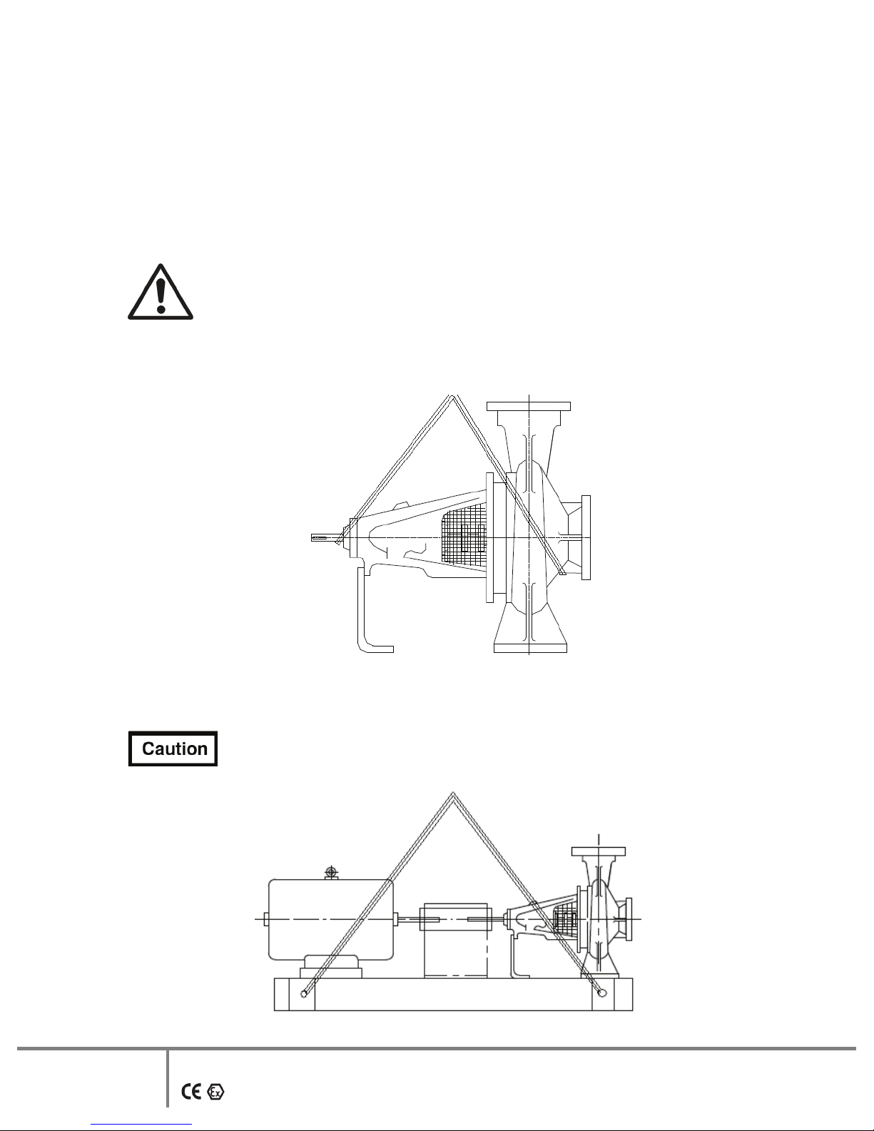
2.6.2 Handling
Crushing hazard
When lifting the pump or pump set, use lifting equipment having a safe working load rating suitable
for the weight specified. Use suitable slings for lifting any pump not provided with lifting points.
The use of suitable forklift truck and four chain crane sling equipment is recommended but locally
approved equipment rating may be used.
Pump should be slung as shown.
Pump set must be lifted from the lifting holes provided using suitable four chain
lifting equipment.
6
This is a proprietary document of Kirloskar Brothers Limited, Kirloskarvadi-416308, Dist-Sangli (India)
ISSUE DATE: 17.09.2010 LAST REV. DATE:
2.6.3 Storage.
2.6.3.1 Temporary storage for up to six weeks.
If the pump unit is not be used immediately it should be stored carefully in a horizontal position, in a
sheltered, dry location.
Additional rust preventive should be applied to all unpainted carbon steel or cast iron
parts, and should not be removed until final installation.
2.6.3.2 Long Term Storage.
Shearing Hazard
DO NOT place fingers or hands etc. into the suction or discharge pipe outlets and do NOT touch the
impeller, if rotated this may cause severe injury. To prevent ingress of any objects, retain the
protection covers or packaging in place until removal is necessary for installation. If the packaging or
suction and discharge covers are removed for inspection purposes, replace afterwards to protect the
pump and maintain the safety.
Fill the bearing housing with recommended oil to ensure that the shaft and bearings remain rust free.
2.6.3.3 Exposed or Extreme Conditions Storage.
For exposed storage or extreme variants in atmospheric or environmental conditions, please refer to
KBL for special storage instructions to suit the conditions acceptable.
3. Equipment schedule
3.1 Installation:
3.1.1 For location, preparing foundation, installation, alignment, general maintenance, trouble
shooting etc. the instructions given in our publication -’GENERAL INSTRUCTIONS FOR
INSTALLATION OPERATION AND MAINTENANCE OF KIRLOSKAR
CENTRIFUGAL PUMPS’ which is also printed along this booklet must be followed very
carefully. If the pump is drawing liquid from the vessel under vacuum, then vacuum
equalizing connection piping must be made as per instruction given in above publication. The
external sealing connection to the pump, if applicable, must be made after installing and
before commissioning the pump.
3.2 MOUNTING AND ALIGNMENT
A flexible coupling is used to connect pump shaft to the driver.
3.2.1 ALIGNMENT
ALWAYS REMEMBER “A FLEXIBLE COUPLING IS NOT A UNIVERSAL JOINT”
Correct alignment is essential for the smooth operation of the pump. There are two types of
misalignment between the pump shaft and the drive shaft, which are:
1) Angular misalignment – shaft with axis concentric, but not parallel.
7
This is a proprietary document of Kirloskar Brothers Limited, Kirloskarvadi-416308, Dist-Sangli (India)
ISSUE DATE: 17.09.2010 LAST REV. DATE:
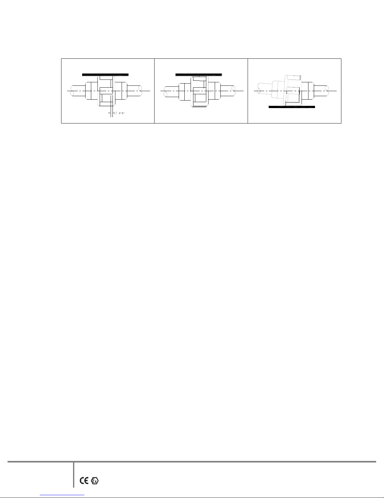
STEEL STRAIGHT EDGE
CORRECT
STEEL STRAIGHT EDGE
INCORRECT PARALLEL
MISALIGNMENT
2) Parallel misalignment – shaft with axis parallel, but not concentric.
This misalignment is checked by using a straight edge as shown in figure given above.
Alternatively it can be checked by any other suitable device like laser.
3.2.1.1 Before commissioning the pump set, please ensure:
A) The pipe connections are flushed and tightened properly.
B) Alignment is proper.
4. Operation
4.1 EQUIPMENT DESCRIPTION:
All ‘DB’ type of pumps are constructed as standard water pumps in accordance with DIN
24255 as far as their main dimensions and performance ratings are concerned. These are
single stage, single suction horizontal shaft, and volute type foot mounted pumps with the
bearing bracket also having a support foot. Mounted pumps with the bearing bracket also
having a support foot. These are centrifugal pumps with enclosed type impeller and are fitted
with standard accessories.
Gland packing or mechanical seal is used to seal the leakage of pumped liquid across the
shaft.
4.2 EQUIPMENT OPERATION.
4.2.1 Before starting the pump check the following:
1) The pump rotates freely by hand.
2) The sealing connections if any, is properly tightened and adjusted.
3) Fill in the grease for bearings, if not done earlier. The bearings are packed with grease
initially at the factory. However, if the pump is stored for longer time it is necessary to
refill the grease bearings.
4) The direction of rotation of driver. It should correspond to the direction of rotation of
pump.
5) The pump casing and the suction pipeline is fully primed with the liquid.
6) Valve on delivery side is closed.
7) Stuffing box packing is properly tightened.
8) The cock for pressure gauge connection is closed.
INCORRECT ANGULAR
MISALIGNMENT
STEEL STRAIGHT EDGE
8
This is a proprietary document of Kirloskar Brothers Limited, Kirloskarvadi-416308, Dist-Sangli (India)
ISSUE DATE: 17.09.2010 LAST REV. DATE:
4.2.2 Starting the pump
1) Start the pump. Let the prime mover pickup its full speed.
2) Open the valve on delivery line gradually.
3) Regulate the required flow by adjusting the delivery valve.
4) Open the cock for pressure gauge connection.
4.2.3 During running the pump check the following things and regulate if needed -
1) The pump is running smooth.
2) The flow of sealing liquid (it external liquid is provided for sealing purpose) is
uninterrupted.
3) Leakage through stuffing box is normal. There should be leakage of 60-80 drops per
minute.
4) The bearings are not getting abnormally hot.
5) Head and capacity developed by the pump is as specified.
6) Power consumption is within limit.
7) Ensure that there is no mechanical friction in the pipe.
8) Stop the pump immediately, if any, defects are detected. Do not start the pump unless the
defects are rectified. Report immediately to the supplier, if it is not possible to rectify the
defects.
4.2.4 During stopping the pump
1) Close the valve on the delivery line.
2) Stop the motor.
3) Close the cooling water and sealing liquid connections.
4) If the pump is not required to be operated for a long time, drain the casing completely. If
the pump is required to be stored for a long time, the bearing housing should be dried
internally with hot air and should be flushed with moisture free protective such as light
oil or kerosene.
5. MAINTENANCE MANUAL
5.1 MAINTENANCE ENVIROMENT, HEALTH AND SAFETY (EHS) INSTRUCTIONS
Following hazards may arise during maintenance work.
Fluid Pressure Jet Hazards
Check and ensure that the pump operates at below the maximum Working Pressure specified.
Hazardous materials:
Wear a suitable mask or respirator when working with chemical material handling.
9
This is a proprietary document of Kirloskar Brothers Limited, Kirloskarvadi-416308, Dist-Sangli (India)
ISSUE DATE: 17.09.2010 LAST REV. DATE:
 Loading...