

Page 1
DP580 Digital Two-way Radio
2
Page 2

T60 Portable PoC Two-way Radio
I
T60 Portable PoC
Two-Way Radio
User Manual
Thank you for choosing Kirisun portable PoC two-way radio.
We believe that the product will bring much convenience to your work and life.
Kirisun portable PoC two-way radio adopts advanced technology and fine technique.
We hope that you will be satisfied with the .quality and functions of the product.
Page 3

I
User Manual
Notice
◆ Please read the manual carefully before using the product. We consider that you have
acquainted with the manual when you start to use the product.
◆ Please keep the manual well for further reference.
◆ The intellectual property of all parts of the product, including accessories, is owned by
Kirisun and its authorized subjects. Without permission of Kirisun and such subjects, no copy,
extraction or translation of such parts is allowed.
◆ The product is subject to change because of upgrading or improvement. Kirisun reserves the
right to change the specifications of software and hardware mentioned in the manual from time
to time without prior notification. The specifications and information in the manual is only for
your reference.
◆ Despite of careful verification, the manual might contain mistakes. Kirisun reserves the right
of final interpretation of the manual.
Page 4

T60 Portable PoC Two-way Radio
III
Safety Precaution
◆ The two-way radio can be repaired only by professional technicians. Users should not
disassemble it by themselves.
◆ To avoid problems caused by electromagnetic interference or electromagnetic
incompatibility, please turn off the radio in a place where you are instructed to do so, for
example, a hospital, a health care center and an aircraft.
◆ In a vehicle with an air bag, please keep the radio out of the expansion area of the air bag.
◆ Do not replace or charge the battery in flammable or explosive environment.
◆ Please turn off the radio near a blast zone or thunder zone.
◆ Do not use the radio if the antenna is damaged, otherwise slight burning might occur when
the antenna contacts the skin.
◆ Make sure the antenna is installed properly before using the radio. A radio not installed with
an antenna is liable to damage while transmitting signals.
◆ When the radio is transmitting, keep it vertical and keep the microphone 5 cm away from
your mouth.
◆ Keep the radio at least 2.5 cm away from your body when the radio is transmitting.
Page 5

I
User Manual
Battery
◆ Contact of conductive substance on human body, for example, jewelry, a key and a bead
necklace, with an exposed battery terminal may result in damage to personal belongings and injury
like burn caused by a high temperature after the battery is short circuited with such substance.
Please handle a charged battery carefully, especially when you put it in a pocket, wallet or metallic
container. To reduce risk of injury, avoid exposure to fire, disassembly or pressing.
◆ The ambient temperature of a power supply unit or a voltage transformer to the charger should
not be higher than 40°C (104°F).
◆ Turn off the radio before charging it. The battery cannot be charged properly if you use the radio
while charging it.
◆ Connect the radio to the charger only when the battery needs to be charged. Continuous charging
will shorten battery life. Do not use the charger as a holder.
◆ For the best battery performance, you are suggested to replace the battery after using it for one
year.
Page 6

T60 Portable PoC Two-way Radio
1
Contents
1. Using the Battery ............................................................................................. 2
2. Using the Accessories ..................................................................................... 4
3. Appearance ..................................................................................................... 8
4. Programming Keys .......................................................................................... 9
5. LED Indicator ................................................................................................. 11
6. Icons.............................................................................................................. 12
7. Basic Operation ............................................................................................. 13
8. Technical Specifications ................................................................................ 20
Page 7

保修卡
2
1. Using the Battery
1.1 Notice for Charging
The radio is delivered uncharged. Before using the radio for the first time, please charge the battery.
If the battery is not used for a long time or run out, please charge it before using it again. It is
necessary to charge and discharge the battery for two or three times to attain the best performance
of it. When you see a warning of low voltage on the radio, please charge or replace the battery.
Notes:
Do not short out battery terminals or discard the battery in fire.
When charging the battery installed on the radio, please power off the radio so that the battery
can be charged fully.
Please take the radio and battery out of the charger when not charging the battery. Continuous
charging will shorten battery life.
Stop charging the battery if it is fully charged, otherwise its cycles of charging and discharging
will be reduced.
Try to keep the battery indoors under a temperature of about 25℃. The battery is liable to fail
after being kept in a low temperature of below -10℃ for a long time.
Under a temperature above 35℃ or below -10℃, the discharge capacity of the battery might
reduce. This is decided by the physical characteristics of lithium battery.
Page 8
3
1.2 Charging
You can charge the battery using one of the following methods.
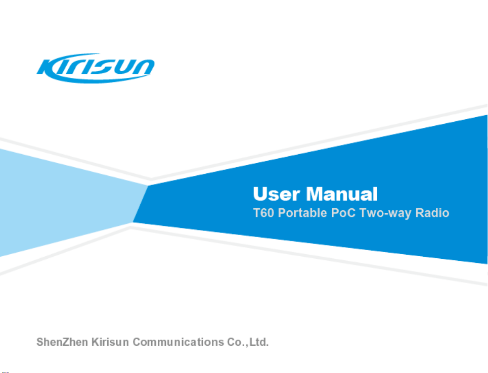
(1) Charging via Micro USB Port on Right Side
a. Open the cover of external interfaces on the right side of the radio to find the
Micro USB port.
b. Connect the port using the programming/charging cable to charge the radio.
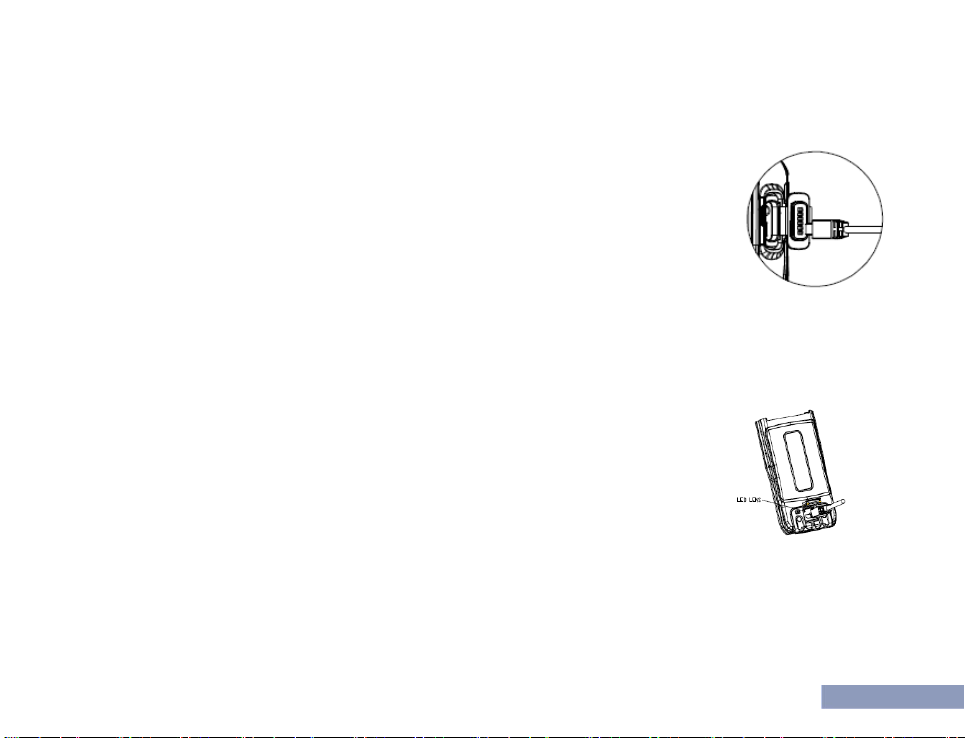
(2) Charging via Micro USB port on Bottom Side
a. Uninstall the battery.
b. Connect the radio to the Micro USB port at the bottom of the radio using the data/charging cable
to charge the radio. Green LED indicator light will be on beside the port.
(3) Charging via Desktop Charger (Optional)
a. Place the desktop charger on a horizontal surface, and keep off
flammables.
b. Plug the power adapter of the charger into an AC power socket, and
connect the power adapter cable to the jack at the back of the charger. Green
LED indicator light will be on.
Page 9

保修卡
4
c. Put the radio (with the battery installed) into the charger to start charging.
Red LED indicator light will be on. Ensure good contact between the battery
and the charging terminals.
d. After charging for about 6 hours, red light will be off and green light on.
Now the battery is fully charged. For optimized battery performance,
continue charging for 1 to 2 hours, and then take out the radio.
e. Unplug the power adapter.
Note:
The radio is delivered uncharged. Before using the radio for the first time, please charge the
battery.
For a new battery or a battery that has been stored for more than 2 months, it is necessary to
charge it for several times to achieve normal battery capacity. Please charge the battery every
three months at least.
To maintain service life and performance of the battery, do not charge a battery that has been
fully charged or before a warning of low voltage is shown on the radio. After charging, take the
battery out of the charger.
When you see a warning of low voltage, please charge the battery before using it again. To
maintain the service life and performance of the battery, do not power on the radio intentionally.
Page 10

5
2. Using the Accessories
2.1 Installing/Uninstalling the Battery
◆Installing the Battery
(1) Press the upper part of the belt clip gently so that it goes up. (Figure ①)
(2) Align the battery with the battery holder at the back of the radio, and then insert the battery.
(Figure ②)
(3) Push the battery in the direction indicated until the latch
is in position. (Figure ③)
(4) Press the upper part of the battery until it is latched.
(Figure ④)
◆Uninstalling the Battery
(1) Power off the radio.
(2) Slide the latch in the indicated direction, and the battery will go up. (Figures ① and ②)
(3) Slice the battery in the indicated direction to take it down. (Figure ③) If the belt clip is installed,
please first press the upper part of it so that it goes up.
Page 11

保修卡
6
Note:
Do not short out battery terminals or discard the battery in fire.
Do not disassemble the battery casing.
2.2 Installing/Uninstalling the Antenna
To install the antenna, plug the threaded end into the antenna interface, and
rotate the antenna clockwise until it is tight.
To uninstall the antenna, rotate it counterclockwise.
2.3 Installing/Uninstalling Belt Clip
To install the belt clip, align the two screw holes on the belt clip with the two at the
back of the radio, and fasten the clip using screws. To uninstall the belt clip,
loosen the screws, and then take off the belt clip.
Page 12

7
2.4 Connecting Programming/Charging Cable
Open the cover of external interfaces on the right side of the radio, find the
Micro USB port, connect the port to a PC using the programming/charging
cable, and write/read parameters using the attached programming
software.
2.5 Connecting an Earphone (Optional)
To use an earphone, open the earphone cover at the upper part of the right
side of the radio, and then plug the earphone connector into the jack.
Page 13

保修卡
8
3. Appearance
Page 14

9
SN
Item
SN
Item
1
Side Key 1
11
LED Indicator
2
PTT Key
12
Microphone
3
Side Key 2
13
Screen
4
Antenna
14
Right Navigation Key
5
Left Menu Key
15
Right Menu Key
6
Left Navigation Key
16
Keypad
7
Speaker
17
External Interfaces
Open the cover to find the
earphone interface and Micro
USB port.
8
Emergency Alarm Key
18
Belt Clip
9
Channel Knob
19
Battery
10
Power/Volume Knob
When the radio is off, rotate it
clockwise to power on the radio;
when the radio is on, rotate it to
adjust the volume, or rotate it
counterclockwise until a “Ka da”
sound is heard to power off.
20
Battery Latch
4. Programming Keys
4.1 Programming Keys
Page 15

保修卡
1
SN
Function
Usage
1
Invalid
No response for key pressing
2
Broadcast
remaining battery
capacity
Voice broadcast of remaining battery capacity
3
Broadcast user
name
Voice broadcast of the user name of the radio
4
Broadcast group
name
Voice broadcast of the name of the group the radio is in
5
Download and play
back voice record
Play 5 previous voice records (with voice recording enabled)
6
Contact list
Display/broadcast contact information
7
Emergency Alarm
Send an emergency alarm
To cater to users’ habits, programmable keys (i.e. two side keys and one top key) are provided,
which can be set as shortcut keys through programming by your dealer.
To program a key, connect the programming/charging cable to the Micro USB port of the radio, and
then program using the attached programming software.
The following functions can be achieved through programming keys.
Page 16

11
LED Indicator State
Device State
Red light on
- No SIM card is installed, or it is installed improperly (with voice
prompt “No SIM card is installed”).
- Fail to unlock the PIN code of the SIM card.
Green light on
- During a call (i.e. individual/group/all call).
Yellow light on
- The device is in individual-call standby state.
- The device is not configured on the server (with voice prompt “Not
configured”).
- The device is expired.
- The device is in standby state or call setup state under duplex talk.
Red light flashes fast
- Network registration fails because of an inactivated SIM card or
overdue charge.
- Device registration fails because of poor wireless network
connection.
Green light flashes slow
- Network registration is successful, and the device enters standby
state.
Yellow light flashes fast
- The device is powered on.
5. LED Indicator
The states of the LED indicator are described in the following table.
Page 17

保修卡
1
LED Indicator State
Device State
No indication
- The device is powered off.
Icon
Description
G/3G received signal strength
2G/3G/4G
E: 2G GPRS transmission;
3G: 3G WCDMA transmission
4G: 4G LTE transmission
Wi-Fi signal strength
Searching GPS satellite signals
GPS signals acquired
In group call
In individual call
Unread emergency alarm message
6. Icons
The following screen icons are used to indicate the state of the radio.
Page 18

13
Icon
Description
Bluetooth enabled, searching for Bluetooth device
Connected to Bluetooth device
Remaining battery capacity
Unread short message
7. Basic Operation
7.1 Powering On/Off
When the radio is off, rotate the Power/Volume knob clockwise until a click is heard to power on the
radio.
When the radio is on, rotate the Power/Volume knob counterclockwise until a click is heard to turn
off the radio.
7.2 Standby State
After the radio registers successfully, it enters standby state so as to save battery consumption to
the greatest extent.
Page 19

保修卡
1
7.3 Adjusting the Volume
When the radio is on, rotate the Power/Volume knob clockwise to increase the volume or
counterclockwise to decrease it.
7.4 Selecting a Group
You can select a group using one of the following methods.
Method 1: After the radio registers successfully and enters standby state, rotate the Group knob to
select a group.
Method 2: In the standby interface, press the Menu key to enter the Menu interface, press navigation
keys to select Group List and then a group, and then press the OK key.
7.5 Initiating a Call
After switching to a group successfully (note: groups are set under the management platform), press
the PTT key to call the default contacts of the current group. If no contact is online, you will hear a
voice prompt “No online group member”, and then transmission request will be interrupted.
7.6 Receiving a Call
After switching to a group successfully (note: groups are set under the management platform), if a
Page 20

15
group member initiates a call, the radio will have green LED indicator light on, and receive traffic
from the group.
7.7 Delayed Callback Admission
Use this function to delay admitting the radio to a group call for a period of time.
7.8 Priority Call
You may set different priorities for different radios, so that a radio with a higher priority can initiate a
call before a radio with a lower priority does and interrupt an ongoing call.
7.9 Call Types
Individual Call
To make an individual call, take the following steps.
1) Entering Individual-Call Mode
Press the programmed Individual Call key (a side key or the top key; for details, see 2. Programming
Keys) to enter individual-call mode.
2) Selecting a Callee Radio
Select a radio, and it will be broadcast.
Page 21

保修卡
1
Note: You may select a callee radio from the Contact List.
3) Initiating an Individual Call
Make sure the radio is normal state (i.e. green light flashes slow). Press the PTT key.
After the call is set up successfully, yellow light will be on, and the callee’s name and call type will be
displayed on the LCD screen. When the callee receives the call, yellow light will be on, and the
caller’s name will be displayed on the LCD screen.
After the call ends, the caller and the callee will have yellow light on.
-Call TOT for Voice
After an individual call is set up, if no voice data is exchanged during 30 seconds, the call will end
and there is voice prompt “Voice timeout”. Then, the caller and callee return respectively to the
group they belong to.
7.10 All Call
An all call is of the highest priority. When an all call is initiated, other calls (including group calls and
individual calls) will be released so as to insert the all call.
Only a special user is privileged to initiate an all call, and such a user is configured via the network
management platform.
Note:
Page 22

17
The default call duration for all types of calls is 60 seconds, which can be modified through the
network management platform. If call duration exceeds this value, the call will end automatically.
7.11 Downloading and Playing Back Video Records
Downloading and Playing Back Video Records
You can download and play back the latest 5 voice records. To achieve this, enable voice recording
and playback under the management platform, and then press the key programmed for downloading
and playing back voice record (for details, see 2. Programmable Keys).
Viewing and Playing Back Video Records
In the standby interface, press the Menu key to enter the Menu interface, press navigation keys to
select Call Records, and then view or play back the latest 30 voice records.
7.12 Submitting Position Information
The radio is positioned through a built-in GPS module, and positioning information is submitted to
the management platform. Real-time position and track of the radio can be displayed on a GIS map
under the platform or via dispatcher software.
7.13 Low-Battery Reminder
Page 23

保修卡
1
When remaining battery capacity is below 10%, there is voice prompt “Low battery, please charge”.
When remaining battery capacity is below 5%, there will be voice prompt “Low battery, please
charge” at an interval. Please replace the battery, or power off the radio and charge the battery.
7.14 Remote Programming
Partial parameters of the radio can be set via the management platform, distributed to the radio via a
2G (GPRS), 3G (WCDMA) or 4G (LTE) network and activated, for example, group settings, terminal
names, functions and permissions.
7.15 Wi-Fi
In the standby interface, press the Menu key to enter the Menu interface, select Settings and then
Wi-Fi, and then enable or disable Wi-Fi function.
After Wi-Fi is enabled, the radio can scan Wi-Fi nearby networks in real time, and a password can be
set.
7.16 Emergency Alarm
To send/exit an emergency alarm, hold down the top key. (Please have the key programmed
beforehand using the attached PC tool.)
Page 24

19
There are two alarm modes as below, which can be set by going to “Menu” “Settings” “Alarm
Modes”.
a. Silent Alarm: Under this mode, the radio sends an emergency alarm silently, and receive an alarm
with voice prompt “SOS alarm from ***”.
b. Alarm and call: If silent alarm is disabled, the radio sends an emergency alarm and rings a siren,
and receive an alarm and rings a siren with voice prompt “SOS alarm from ***”.
To view sent alarms and received alarms, go to “Menu” “Message Records” “SOS Messages”.
7.17 Advanced Functions
Activation, stunning, killing and monitoring of the radio and voice playback can be achieved via
dispatcher software.
Page 25

保修卡
2
General
Communication System
& Frequency Bands
GSM/GPRS: 850
WCDMA/HSPA: B5
FDD-LTE: B4/5/7/17
Storage Temperature
-40℃ ~ + 80℃
Operating Temperature
-20℃ ~ + 40℃
Water and Dust
Resistance
IP 54
Dimension (H*W*D)
115mm*54mm*30mm (battery included, antenna
excluded)
Weight
330g (battery and antenna included)
Screen
160*128 pixels, monochrome screen
Keypad
Qwerty
Battery
3600mAh Li-ion
Operating Voltage
3.7V DC
Standby Duration
(3600mAH battery)
2G: 22 hrs (GPS on), 25 hrs (GPS off)
3G: 15 hrs (GPS on), 16 hrs (GPS off)
8. Technical Specifications
Page 26

21
4G: 13 hrs (GPS on), 15 hrs (GPS off)
Transmitter
Transmitting Power
2G: 33dBm±2dB
3G: 24dBm+1/-3dB
4G: 23dBm+1/-3dB
Audio Distortion
5% (typical)
Receiver
Receiving Sensitivity
2G:BER < 0.001 when Îor = -106.7 (-108) dBm
3G: BER < 0.001 when Îor = -106.7 (-108) dBm
4G:BER < 0.001 when Îor = -98 (-100) dBm
Audio Power
1W
Audio Distortion
5% (typical)
Page 27

保修卡
2
FCC Statement
15.19 Labeling requirements.
This device complies with part 15 of the FCC Rules. Operation is subject to the following
two conditions: (1) This device may not cause harmful interference, and (2) this device
must accept any interference received, including interference that may cause undesired
operation.
15.21 Information to user.
Any Changes or modifications not expressly approved by the party responsible for
compliance could void the user's authority to operate the equipment.
15.105 Information to user.
This equipment has been tested and found to comply with the limits for a Class B digital
device, pursuant to Part 15 of the FCC Rules. These limits are designed to provide
reasonable protection against harmful interference in a residential installation. This
equipment generates uses and can radiate radio frequency energy and, if not installed and
used in accordance with the instructions, may cause harmful interference to radio
communications. However, there is no guarantee that interference will not occur in a
particular installation. If this equipment does cause harmful interference to radio or
television reception, which can be determined by turning the equipment off and on, the
user is encouraged to try to correct the interference by one or more of the following
measures:
-- Reorient or relocate the receiving antenna.
-- Increase the separation between the equipment and receiver.
-- Connect the equipment into an outlet on a circuit different from that to which the receiver
Page 28

23
is connected.
-- Consult the dealer or an experienced radio/TV technician for help.
Specific Absorption Rate (SAR) information:
This product meets the government's requirements for exposure to radio waves. The
guidelines are based on standards that were developed by independent scientific
organizations through periodic and thorough evaluation of scientific studies. The
standards include a substantial safety margin designed to assure the safety of all persons
regardless of age or health.
FCC RF Exposure Information and Statement The SAR limit of USA (FCC) is 1.6 W/kg
averaged over one gram of tissue. This device was tested for typical body-worn operations
with the back of the handset kept 0mm from the body and 25mm front of face. To maintain
compliance with FCC RF exposure requirements, use accessories that maintain a 0mm
separation distance between the user's body and the back of the handset. The use of belt
clips, holsters and similar accessories should not contain metallic components in its
assembly. The use of accessories that do not satisfy these requirements may not comply
with FCC RF exposure requirements, and should be avoided.
Body-worn Operation
This device was tested for typical body-worn operations. To comply with RF exposure
requirements, a minimum separation distance of 0mm for body and 25 front of face worn
must be maintained between the user’s body, including the antenna. Third-party belt-clips,
holsters, and similar accessories used by this device should not contain any metallic
components. Body-worn accessories that do not meet these requirements may not comply
with RF exposure requirements and should be avoided. Use only the supplied or an
approved antenna.
Page 29

保修卡
2
IC Statement
IC STATEMENT
This device complies with Industry Canada’s licence-exempt RSSs. Operation is subject
to the following two conditions:
(1) This device may not cause interference;
(2) This device must accept any interference, including interference that may cause
undesired operation of the device.
Le présent appareil est conforme aux CNR d'Industrie Canada applicables aux appareils
radio exempts de licence. L'exploitation est autorisée aux deux conditions suivantes: (1)
l'appareil ne doit pas produire de brouillage, et (2) l'utilisateur de l'appareil doit accepter
tout brouillage radioélectrique subi, même si le brouillage est susceptible d'en
compromettre le fonctionnement.
IC SAR warning:
The information listed above provides the user with information needed to make him or her
aware of a RF exposure, and what to do to assure that this radio operates within the FCC
exposure limits of this radio.
The device complies with RF specifications when the device used at 0mm from the body
and 25mm front of face. Third-party belt-clips, holsters, and similar accessories used by
this device should not contain any metallic components. Body-worn accessories that do
not meet these requirements may not comply with RF exposure requirements and should
be avoided.
Page 30

25
 Loading...