

Page 1
M50 PoC Mobile Radio
2
Page 2

M50 PoC Mobile Radio
I
M50 PoC Mobile Radio
User Manual
Thank you for choosing Kirisun PoC mobile radio.
We believe that the product will bring much convenience to your work and life.
Kirisun vehicle-mounted mobile radios adopt advanced technology and fine technique.
We hope that you will be satisfied with the quality and functions of the product.
Page 3

User Manual
II
Notice
◆ Please read the manual carefully before using the product. We consider that you have
acquainted with the manual when you start to use the product.
◆ Please keep the manual well for further reference.
◆ The intellectual property of all parts of the product, including accessories, is owned by
Kirisun and its authorized subjects. Without permission of Kirisun and such subjects, no
copy, extraction or translation of such parts is allowed.
◆ The product is subject to change because of upgrading or improvement. Kirisun
reserves the right to change the specifications of software and hardware mentioned in the
manual from time to time without prior notification. The specifications and information in
the manual is only for your reference.
◆ Despite of careful verification, the manual might contain mistakes. Kirisun reserves the
right of final interpretation of the manual.
Page 4

III
M50 PoC Mobile Radio
Safety Precaution
To prevent fire, personal injury and damage to the radio, please abide by the followings.
◆ According to governmental decrees, it is prohibited to operate radio transmitters
without permission within the area of its jurisdiction. Violation to such stipulations may
result in penalty or arrest. Maintenance of the product can only be performed by
professional technicians.
◆ For safety, it is important for a user to learn knowledge of common hazards before
using a radio transmitter.
◆ Power off the radio in an explosive environment with dangerous gas, dust or mist, for
example, a gas station where you refuel or park a vehicle.
◆ It is suggested to have the radio transmit traffic for not longer than 1 minute
continuously and receive for not longer than 4 minutes at a time. Transmissions for a long
time or continuous operation under high power will result in overheat at the back of the
radio.
Page 5

IV
User Manual
◆ Never disassemble the radio by yourself.
◆ Keep the radio away from continuous direct sunshine. Do not place the radio near a
heater.
◆ Do not place the radio in a place with much dust, moist or splash of water, or on an
unstable surface.
◆In case the radio discharges smell or smoke, power off the radio immediately and
contact the local dealer.
Page 6

M50 PoC Mobile Radio
V
Contents
1. Unpacking ............................................................................................................................ 1
2. Overview ............................................................................................................................... 3
2.1 Appearance .................................................................................................................. 3
2.2 Installation ..................................................................................................................... 5
2.3 Programming Keys ...................................................................................................... 7
2.4 LED Indicator ................................................................................................................ 8
2.5 Icons .............................................................................................................................. 9
3. Basic Functions ................................................................................................................ 11
3.1 Powering On/Off ........................................................................................................ 11
3.2 Standby Mode ............................................................................................................ 11
3.3 Adjusting the Volume ................................................................................................ 12
3.4 Selecting a Group ...................................................................................................... 12
3.5 Initiating a Call ............................................................................................................ 13
3.6 Receiving a Call ................................................................................................ ......... 13
3.7 Delayed Callback Admission ................................................................................... 13
3.8 Priority Call ................................................................................................................. 13
Page 7

User Manual
V
3.9 Call Types ................................................................................................................... 14
3.10 Downloading and Playing Back Video Records .................................................. 20
3.11 GPS Function ........................................................................................................... 20
3.12 Wi-Fi Function .......................................................................................................... 21
3.13 Bluetooth ................................................................................................................... 22
3.14 Fan ............................................................................................................................. 23
3.15 Backlight ................................................................................................................... 23
3.16 Alarm Modes ............................................................................................................ 24
3.17 Language Setting .................................................................................................... 26
3.18 Device Information .................................................................................................. 26
3.19 Advanced Functions................................................................................................ 26
4. Technical Specifications ................................................................................................ 27
4. Troubleshooting ............................................................................................................... 30
Page 8

M50 PoC Mobile Radio
1
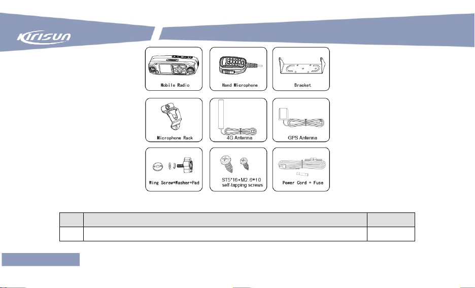
1. Unpacking
Open the packing box carefully and find the parts as listed below. If any item is missing or
damaged, please contact the dealer.
Page 9
2
SN
Item
Quantity
1
Radio
1
User Manual
Please find the following items in the package.
Page 10

M50 PoC Mobile Radio
3
2
Hand Microphone
1
3
Bracket (with four M5*16 self-tapping screws)
1
4
Power Cord
1
5
4G Main Antenna
1
6
GPS Antenna
1
7
ST5*16 self-tapping screw
4
8
Wing screw (including flat washer, spring washer and plastic pad)
2
9
Fuse
1
10
3M Adhesive Sticker
1
11
Certificate of Approval
1
12
User Manual
1
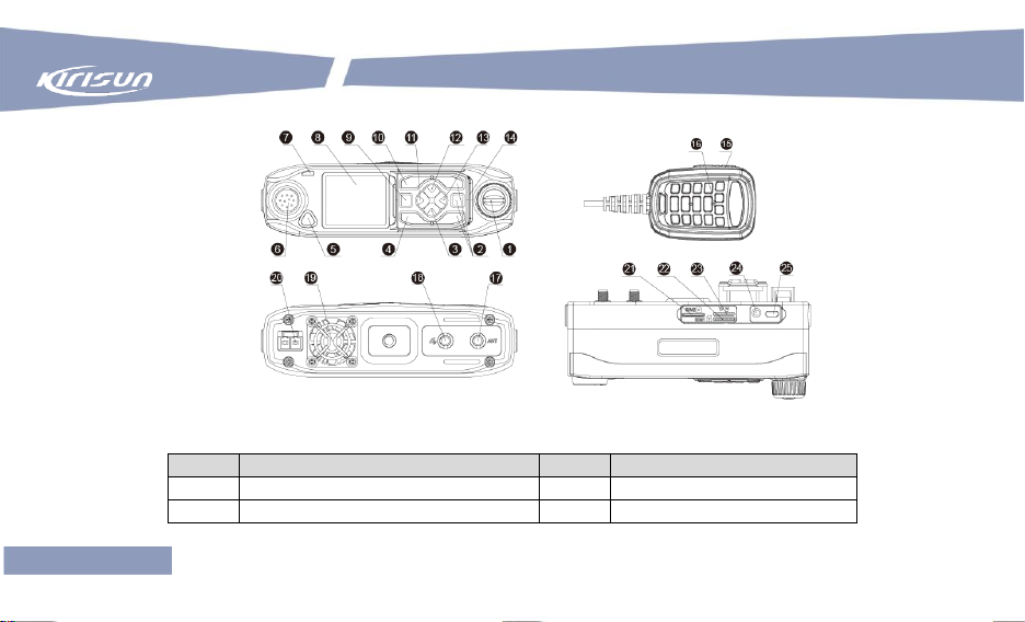
2. Overview
2.1 Appearance
Page 11
User Manual
4
SN
Item
SN
Item
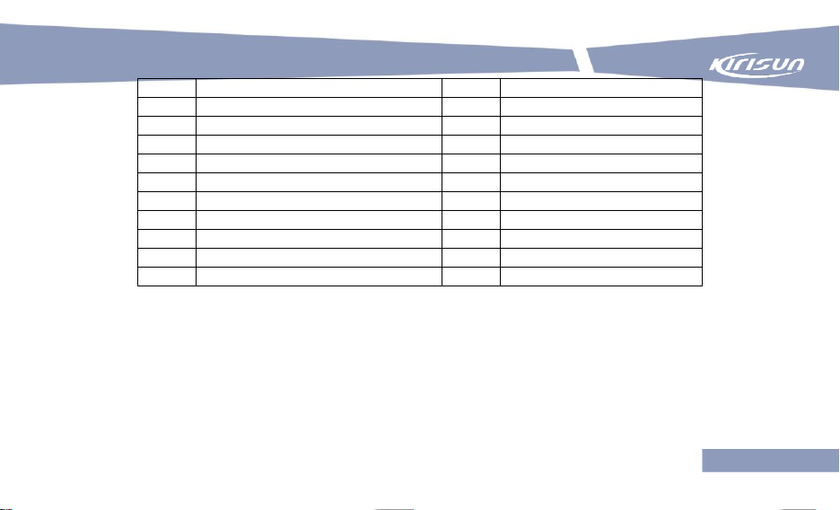
1
Volume Knob
14
Speaker
2
P1~P3 (Programmable Keys)
15
PTT Key
Page 12
M50 PoC Mobile Radio
5
3
Down Key
16
Hand Microphone
4
Return Key
17
Antenna Interface
5
Emergency Alarm Key
18
GPS Antenna Interface
6
Hand Microphone Connector
19
Fan
7
LED Indicator
20
Power Interface
8
LCD Screen
21
SIM Card Slot 2
9
Power Key
22
SIM Card Slot 1
10
Menu Key
23
TF Card Slot
11
Left Key
24
Earphone Jack
12
Up Key
25
USB Port
13
Right Key
2.2 Installation
Attentions:
The radio should be installed in a position where it can be used conveniently and personal
Page 13

User Manual
6
injury can be avoided while driving a vehicle in poor road condition.
While drilling holes, protect the internal wires of a vehicle or of other devices from being
damaged.
Leave enough space behind the radio for wiring.
Make sure the power cord is long enough so that the radio can be maintained with the
power connected.
While replacing the fuse, make sure a fuse meeting requirements is used.
Installation Steps
1. Fix the bracket at a position in a vehicle where operation is convenient using the four M5*16
self-tapping screws.
2. Fix the mobile onto the bracket using the two wing screws.
3. Wire the 3-meter power cord, connect its open end to the engine battery or other power supply
(with supply voltage not higher than 26V). Make sure the red wire is connected to the anode and
Page 14

M50 PoC Mobile Radio
7
the black wire to the cathode. Install the supplied fuse, and connect the power plug to the power
interface at the rear of the radio.
4. Connect the 4G antenna and the GPS antenna respectively according to the indications at the
rear of the radio.
5. Plug the hand microphone (with the direction sign up) into the corresponding interface of the
radio, and rotate clockwise the cover lock on the plug. When the lock contacts the slot on the
radio, press it a bit and continue to rotate it until it is tightened.
6. Fix the magnetic microphone rack at a position for you to operate it conveniently and drive
safely using the three M2.6*10 self-tapping screws to fix the microphone stand onto a position
where operation is convenient, and have the microphone attracted to the rack.
Installing/Uninstalling Hand Microphone
To install the hand microphone, plug the hand microphone (with the direction sign up) into the
corresponding interface of the radio, and rotate clockwise the cover lock on the plug. When the
Page 15

User Manual
8
lock contacts the slot on the radio, press it a bit and continue to rotate it until it is tightened.
2.3 Programming Keys
To cater to users’ habits, the programmable keys P1, P2 and P3 can be set as shortcut keys
through programming by your dealer.
The following functions can be achieved through programming keys.
Page 16

M50 PoC Mobile Radio
9
Shortcut Key
Operation
Function
P1
Press
Broadcast group name
Press and hold
Download and play back video records
P2
Press
Broadcast user name
Press and hold
Enter individual-call mode
P3
Press
Enable/disable Bluetooth
Press and hold
Enable/disable Wi-Fi
Indicator State
Device State
Red light on
A. No SIM card is installed, or it is installed improperly (with voice prompt “No
SIM card is installed”).
B. Fail to unlock the PIN code of the SIM card.
Green light on
A. During a call (i.e. individual/group/all call).
B. The device is powered on.
2.4 LED Indicator
The states of the LED indicator are described in the following table.
Page 17

User Manual
10
Yellow light on
A. The device is in individual-call standby state.
B. The device is not configured on the server (with voice prompt “Not
configured”).
C. The device is expired.
D. The device is in standby state or call setup state under duplex talk.
Red light flashes
fast
A. Network registration fails because of an inactivated SIM card or overdue
charge.
B. Device registration fails because of poor wireless network connection.
Green light flashes
slow
Network registration is successful, and the device enters standby state.
No indication
The device is powered off.
Icon
Description
2.5 Icons
The following screen icons are used to indicate the state of the radio.
Page 18

M50 PoC Mobile Radio
11
Icon
Description
2G/3G/4G received signal
strength indication
Wi-Fi received signal strength
indication
Searching GPS satellite signals
GPS signals acquired
In group call
In individual call
In all call
Under dispatching
Unread short message
3. Basic Functions
Page 19

12
User Manual
3.1 Powering On/Off
Powering On
When the radio is off, supply a voltage of 12~24V, and the radio will be powered on
automatically within about 30s.
When the radio is in soft off state, you can start it by pressing and holding for 3s before
release.
Powering Off
When the radio is on, you can power it off by pressing and holding for 5s before release.
3.2 Standby Mode
Press , and the radio will enter standby mode so as to save battery consumption to the
greatest extent.
Page 20

13
M50 PoC Mobile Radio
3.3 Adjusting the Volume
In the main interface, rotate the Volume knob clockwise to increase the volume or
counterclockwise to decrease it.
3.4 Selecting a Group
In the main interface, you can switch to another group in the zone by pressing / on the
hand microphone or by pressing / on the radio.
In the main interface, select Menu, Group List and then a group.
3.5 Initiating a Call
Page 21

14
User Manual
If the current channel has been mapped (under the management platform), you can call the
default contract of the channel by pressing the PTT key on the hand microphone.
3.6 Receiving a Call
If the current channel has been mapped (under the management platform), the radio will output
voice after receiving an individual call or a group call on the channel.
3.7 Delayed Callback Admission
Use this function to delay admitting the radio to a group call for a period of time.
3.8 Priority Call
You may set different priorities for different radios, so that a radio with a higher priority can
Page 22

15
M50 PoC Mobile Radio
initiate a call before a radio with a lower priority does and interrupt an ongoing call.
3.9 Call Types
Group Call
After the radio is powered on, it enters group-call standby state, and the radio may be in a valid
group with green light flashing slowly or an invalid group (that is not configured) with red light on.
To make a group call, take the following steps.
(1) Selecting a Group
Select a group by pressing / on the hand microphone or by pressing / on the radio.
(2) Initiating Group Call
Make sure the radio is in normal state (i.e. green light flashes slowly), and then press the PTT
key and hold. Then,
Page 23

16
User Manual
If another radio in the group is online, a group call will be initiated, with green light on and
the group name and call type icon displayed on the screen.
When a callee receives the call, it will have green light on and the group name, the group
type and the caller name displayed on the screen.
When the call is over, the callee will ring a short tone “Di” and green light will flash slowly.
If no radio in the group is online, green light will flash once and “No answer” will be
displayed on the screen. Release the PTT key to end the call, and the radio will enter
group-call standby state.
Individual Call
To make an individual call, take the following steps.
(1) Setting Contact List
Under the management platform, set contacts for the radio.
(2) Entering Individual-Call Mode
Page 24

17
M50 PoC Mobile Radio
Take one of the following methods to enter individual-call mode.
Press the shortcut key P2 and hold.
In the main interface, select Menu and then Contacts.
(3) Selecting a Contact
Go to the Contact interface, select a contact, and then press the OK/Menu key on the hand
microphone or on the radio.
(4) Initiating Individual Call
Make sure the radio is in normal state (i.e. green light flashes slowly), and then press the PTT
key and hold. Then,
If the callee is online and idle, an individual call will be initiated, with green light on and the
callee name and call type icon displayed on the screen.
When the callee receives the call, it will have green light on and the caller name displayed
on the screen.
When the call is over, both the caller and the callee will ring a short tone “Di” and green
Page 25

18
User Manual
light will flash slowly.
If the callee is offline or is busy, green light will flash once and “No answer” will be
displayed on the screen. Release the PTT key to end the call, and the radio will return to
the previous interface.
After an individual call ends, the caller will return to its previous state. Within 5s after an
individual ends, the callee may call the caller back by pressing the PTT key, or exit individual-call
state and return to its previous state without any operation.
Note:
An individual call has a higher priority than a group call does. An individual call can be made
cross two groups, no matter which group the callee is in.
The default call duration for an individual call is 40 seconds, which can be modified through a
configuration tool. If call duration exceeds this value, the call will end automatically.
All Call
Page 26

19
M50 PoC Mobile Radio
An all call is of the highest priority. When an all call is initiated, other calls (including group calls
and individual calls) will be released so as to insert the all call.
To make an all call, take the following steps.
(1) Selecting a Group
If an all-call group has been configured for the radio under the management platform, you may
select the group by pressing the Menu key to enter the Menu interface and then selecting Group
List.
(2) Initiating All Call
Make sure the radio is in normal state (i.e. green light flashes slowly), and then press the PTT
key and hold. Then,
If a member radio in the group is online (in idle, individual-call, group-call or duplex
transmission), an all call will be initiated, with green light on and the group name and call
type icon displayed on the caller screen. When a callee receives the call, it will switch
Page 27

20
User Manual
to all-call mode, and will have green light on and the group name, group type and caller
name displayed on the screen. When the call is over, the callee will ring a short tone “Di”
and green light will flash slowly.
If no member radio in the group is online, green light will flash once and “No answer” will be
displayed on the caller screen. Release the PTT key to end the call, and the radio will
return all-call standby state
After an all-call ends,
A callee will exit all-call state and return to its previous state if no radio (either the caller or a
callee) calls within 30s; the caller will keep waiting for an all-call unless it exits the group
(through the menu or by rotating the Channel knob).
If the caller exits the group (in all-call standby state or all-call state), all callees will also exit
all-call state and return to their previous states. Change of group types will be shown on
screens.
Page 28

21
M50 PoC Mobile Radio
Note:
It is suggested that only a special user is privileged to initiate an all call.
The default call duration for an all call is 30 seconds, which can be modified through a
configuration tool. If call duration exceeds this value, the call will end automatically.
3.10 Downloading and Playing Back Video Records
To download and play back the latest 5 voice records, enable voice recording and playback
under the management platform, and then press and hold the shortcut key P1.
To view and play back the latest 30 call records, in the main interface select Menu and then
Call Records.
3.11 GPS Function
The radio is positioned through a built-in GPS module, and positioning information is submitted
Page 29

22
User Manual
to the management platform. Real-time position and track of the radio can be displayed on a GIS
map under the platform or via dispatcher software.
Enabling/Disabling GPS Function
In the main interface, select Menu, Settings and then GPS On/Off, and then press the Menu key
on the hand microphone/radio or the Volume knob to enable or disable GPS function.
3.12 Wi-Fi Function
Enabling/Disabling Wi-Fi
In the main interface, select Menu, Settings and then Wi-Fi, and then the Menu key on the hand
microphone/radio or the Volume knob to enable or disable Wi-Fi function.
Setting Wi-Fi Network Password
Page 30

23
M50 PoC Mobile Radio
Enable Wi-Fi, select Scan to scan nearby Wi-Fi networks. Select a network, and you will be
prompted to set a password. Press OK to go to the password setting interface. Set a password
by inputting numbers or English letters using the microphone keypad. (You can switch to another
input mode by pressing #.)
Viewing and Deleting Wi-Fi Networks
You can view or delete saved networks by selecting Saved Networks.
3.13 Bluetooth
Enabling/Disabling Bluetooth
In the main interface, select Menu, Settings and then Bluetooth, and then press the Menu key on
the hand microphone/radio or the Volume knob to enable or disable Bluetooth.
Pairing
Page 31

24
User Manual
Enable Bluetooth, select Scan to scan nearby Bluetooth devices. Select a device, and you will be
prompted for pairing. Press OK to start pairing the device and the radio.
Viewing Paired Devices
You can view paired devices by selecting Paired Devices.
3.14 Fan
In the main interface, select Menu, Settings and then Fan, press the Menu key on the hand
microphone/radio or the Volume knob, and then select Enable, Disable or Auto.
After selecting Auto, select 45°C, 55°C or 65°C (i.e. the fan is on when the radio reaches the
temperature, and is off when the radio is under the temperature).
3.15 Backlight
Page 32

25
M50 PoC Mobile Radio
In the main interface, select Menu, Settings and then Backlight Level, press the Menu key on the
hand microphone/radio or the Volume knob, and then select Low, Medium or High by pressing
arrow keys.
3.16 Alarm Modes
Selecting Silent Receiving or/and Silent Sending
In the main interface, select Menu, Settings and then Alarm Modes, press the Menu key on the
hand microphone/radio or the Volume knob, and then select Silent Receiving or/and Silent
Sending.
Silent Receiving
When silent receiving is enabled, there will be LED indication but no voice prompt when an alarm
is received.
When silent receiving is disabled, there will be LED indication and voice prompt when an alarm is
Page 33

26
User Manual
received.
Silent Sending
When silent sending is enabled, there will be LED indication but no voice prompt when an alarm
is sent.
When silent sending is disabled, there will be LED indication and voice prompt when an alarm is
sent.
Alarm Message
When an alarm is sent/received, a textual message will be generated on the caller/callee. To
view sent/received alarms, go to “Menu” “Message Records” “SOS Messages”.
Sending an Alarm
To send an alarm, press the orange Emergency Alarm key.
Page 34

27
M50 PoC Mobile Radio
3.17 Language Setting
In the main interface, select Menu, Settings and then Language Setting, press the Menu key on
the hand microphone/radio or the Volume knob, and then select Chinese, English, Turkish or
Greek.
3.18 Device Information
In the main interface, select Menu, Settings and then Device Info, press the Menu key on the
hand microphone/radio or the Volume knob, and then view the IMEI NO., software version and
system version.
3.19 Advanced Functions
Page 35

User Manual
28
General
Communication System & Frequency Bands
TDD-LTE: Band 40(only for CE band)
FDD-LTE: Band 1/3/4/5/7/8/17/20/28A
WCDMA: Band 1/5/8
GSM/GPRS: 850/900/1800 MHZ
Wi-Fi: 2.4GHz/5GHz
Operation Temperature
-20℃ ~ + 50℃
Storage Temperature
-40℃ ~ + 80℃
Operating Voltage
DC12-24V
Dimension (H*W*D)
152.6mm*43.4mm*49mm
Activation, stunning, killing and monitoring of the radio and voice playback can be achieved via
dispatcher software.
4. Technical Specifications
Page 36

M50 PoC Mobile Radio
29
Weight
≤250g (radio only)
Screen
160*128 pixels, monochrome
Water and Dust Resistance
IP54
Transmitter
Transmitting Power
GSM850/900 MHZ
33dBm (+2/-2dB)
DCS1800 MHZ
30dBm (+2/-2dB)
WCDMA
24dBm (+1/-3dB)
FDD-LTE/ TDD-LTE
23dBm (+2/-2dB)
Frequency Stability
±0.1 ppm
Audio Distortion
5% (typical)
Receiver
Frequency Stability
±0.1 ppm
Receiving Sensitivity
GSM/GPRS
≤ -102dBm
WCDMA
B1≤-106dBm
Page 37

User Manual
30
B5≤-104dBm
B8≤-103dBm
FDD-LTE
≤-97dBm (bandwidth:
10M)
TDD-LTE
≤-94dBm (bandwidth:
20M)
Audio Power
1W
Audio Distortion
5% (typical)
Failure
Description
Reason
Solution
Startup failed
Loose power plug
Make sure the plug is in position.
4. Troubleshooting
Page 38

M50 PoC Mobile Radio
31
Failure
Description
Reason
Solution
Battery/supply voltage
below 6V
Ensure a supply voltage of at least 6V.
Burnt fuse
Replace the fuse with a new one, make
sure correct connection of the anode and
cathode of power supply, and then power
on the radio.
Low, interrupted
or no volume
while receiving
traffic
Low supply voltage
Fully charge the battery before using the
radio, or change for power supply with a
voltage of 10.8V
Low volume
Turn up the volume.
Loosen antenna or not in
position
Power off the radio and install the
antenna properly.
Page 39

User Manual
32
Failure
Description
Reason
Solution
Blocked or destroyed
speaker
Clean the outside of the radio. If the
problem remains, contact your dealer or
an authorized maintenance provider for
examination and repair.
Talk failed
Incorrect platform
parameter settings
- Incorrect channel settings
Set parameters properly and try again.
- Wrong default call group
Select a right group and try again.
GPS positioning
failed
No GPS signals received
at the position
Move to an open and flat area.
Page 40

33
M50 PoC Mobile Radio
FCC Statement
15.19 Labeling requirements.
This device complies with part 15 of the FCC Rules. Operation is subject to the
following two conditions: (1) This device may not cause harmful interference, and (2)
this device must accept any interference received, including interference that may
cause undesired operation.
15.21 Information to user.
Any Changes or modifications not expressly approved by the party responsible for
compliance could void the user's authority to operate the equipment.
15.105 Information to user.
This equipment has been tested and found to comply with the limits for a Class B digital
device, pursuant to Part 15 of the FCC Rules. These limits are designed to provide
reasonable protection against harmful interference in a residential installation. This
equipment generates uses and can radiate radio frequency energy and, if not installed
and used in accordance with the instructions, may cause harmful interference to radio
communications. However, there is no guarantee that interference will not occur in a
Page 41

34
保修卡
particular installation. If this equipment does cause harmful interference to radio or
television reception, which can be determined by turning the equipment off and on, the
user is encouraged to try to correct the interference by one or more of the following
measures:
-- Reorient or relocate the receiving antenna.
-- Increase the separation between the equipment and receiver.
-- Connect the equipment into an outlet on a circuit different from that to which the
receiver is connected.
-- Consult the dealer or an experienced radio/TV technician for help.
During operation, the separation distance between user and the antenna shall be at
least 20cm, this separation distance will ensure that there is sufficient distance from a
properly installed externally-mounted antenna to satisfy the RF exposure requirements.
 Loading...