

Page 1

PT8200
VHF /UHF MOBILE RADIO
SERVICE MANUAL
V070828
Page 2

PT8200 SERVICE MANUAL
DANGEROUS!!
Do not connect AC power or the DC power that
exceeds the specified input value with any
connector or terminals of the radio. Otherwise it will
cause fire or electric shock.
WARNING
Do not reverse power connection.
It may cause harm to the radio if signal input on the
antenna connector is bigger than 20 dBm (100mW).
Do not turn on the power before the antenna or load
connection is completed.
If the antenna has been damaged, do not use the radio.
Damaged antenna may cause tightly burning on skin.
CONTENTS
Chapter 1 Introduction ......................................................2
Chapter 2 Radio ................................................3
Chapter 3 ...................4
Chapter 4 Disassembly For Repair ..........................................5
Chapter 5 ..................7
Chapter 6 ..............................................9
Chapter 7 .............................10
Chapter 8 ...........................................................22
Chapter 9 ...........................................24
Chapter 10 ................................37
Chapter 11 ...............................37
Chapter 12 ................................... 38
Chapter 13 .....................38
Chapter 14 Appendix...................... .................. .....39
Mode Combinations.................................
Circuit Description.....................................
Semiconductor Data..
Description of Components........
Adjustment
PCB Diagram..............
Interface Functions................
Packing...................................
Troubleshooting................
Specifications Parameters................
.......
Overview.......
................
It's better to avoid putting it in rain or snow, or any other
liquid to ensure its life and performance.
STATEMENT
Kirisun Electronic (Shenzhen) Co., Ltd owns the copyright
of KSP8200 software.
Unauthorized Duplication of KSP8200 software is strictly
prohibited.
Kirisun Electronic (Shenzhen) Co., Ltd owns the copyright
of the MCU software.
Kirisun Electronic (Shenzhen) Co., Ltd owns the copyright
of the radio outward/structure/circuit design.
Kirisun Electronic (Shenzhen) Co., Ltd owns the copyright
of this service manual. Unauthorized publication is
prohibited.
Kirisun Electronic (Shenzhen) Co., Ltd owns the
trademarks KIRISUN , , .
1
Page 3
PT8200 SERVICE MANUAL
Chapter 1 Introduction
1.1 Introduction
This manual applies to the service and maintenance of PT8200 series of
FM mobile radio, and is designed for the engineers and professional
technicians that have been trained by our company. In this manual you
can find all the information of product service. Kirisun reserves the rights
to modify the product construction and specification without notice in
order to enhance product performance and quality. You can also log on
our website www.kirisun.com to download the latest service manual or
contact your local dealer or us.
Read this manual before repair the product.
1.2 Service Precautions
Safety
Avoid skin contacting with the antenna connector and PCB.
Do not reverse the power polarities.
If signal input is bigger than 20dBm (100mW) it may cause damage to
the radio.
Do not turn on the power before the antenna and load connection is
completed.
Do not use the radio if the antenna has been damaged. Contact the
damaged antenna will cause lightly burning on the skin.
Repair service can only conducted by professional technicians.
Electromagnetism Interference
It's prohibited to use or repair the radio in the following places:
Hospital, health center, air port
Any area with a potentially explosive atmosphere (where the air contains
gas, dust and smog, etc.), such as the storage or transportation facilities.
Any area of dynamite or exploder.
Change Components
All the components use in repair service should be supplied by
Kirisun.
Other components of the same models available on the market are not
surely able to use in this product and we do not guarantee the quality of
the product using such components.
Please fill in the following forms if you want to apply for any components
from Kirisun.
Component Application
Radio M o del/
Model
Compo
nent
No.
pecifications
S
Mat e r i a l Serial
No.
Qua
ntity
Installation Condition
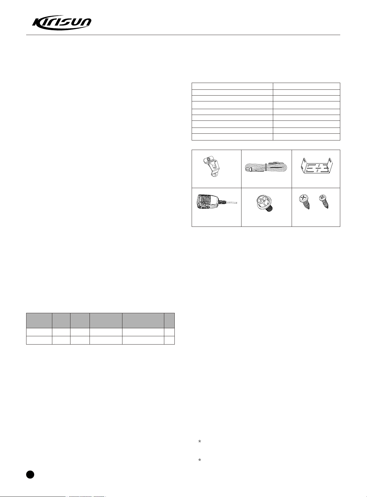
1.Unpack
Please check the host in the package and the supplied accessories in
the following table before using. Any articles are found lost or damaged,
please contact the distributor without delay.
Accessories
Fixed bracket
Power Cable
Hand Microphone
Microphone Hanger
M4*10 Combination Screw
M4*16 Self-tapping Screw
M5*16 Self-tapping Screw
Instruction Manual
Microphone Hanger
Hand Microphone
2. Licenses
Rules require that the radio installation point (mobile station or base
station) needs permission license. The license carrier guarantees that
the RF power, frequency and frequency deviation comply with the
license requirements. The radio assembling or operation must be
conducted by the license-authorized technicians.
3. Installation Preparation
3.1 Description
Every radio has been adjusted and checked before the shipment. Before
installation it's better to check if the radio transmitting or receiving is
normal to make sure its proper operation.
3.2 Test
Connect all the cables and accessories to test the radio.
Transmitter frequency, deviation, and power output should be
checked, as should receiver sensitivity, squelch operation, and
audio output. Signlling operation should be verified.
Power Cable
M4*10 Combination
Screw
Quantity
1
1
1
1
4
2
4
1
Fixed bracket
M5*16 / M4*16
Self-tapping Screw
1.3 Service
All the Kirisun products are subject to the service warranty.
The main unit of the radio is guaranteed for free service of 24 months.
Accessories (such as battery pack, power adapter, antenna or charger)
are guaranteed for free service of 6 months. Earphones are wearing
parts and out of warranty.
In one of the following situations, charge free service will not be
available.
No valid service warranty or original invoice.
Malfunction caused by disassembling, repairing or reconstructing the
radio by the users without permission.
Wearing and tearing or any man-made damage such as mechanical
damage, burning or water leaking.
Product serial number has been damaged or the product trademark is
difficult to identify.
After the warranty expires, lifetime service is still available. And we also
provide service components to service stations and service staff.
2
4. Installation Steps
4.1 Introduction
Check the car and decide how and where to install the radio antenna
and accessories. Allocate the cable in a proper place to avoid pressing
or squeezing it. And pay attention to the heat scattering of the radio
equipments.
4.2 Antenna
The most ideal place for antenna is the center of an open and flat
conduction region. It usually at the center of the car top or at the top of the
luggage cabinet. Stick the ground wire at the top of the luggage cabinet
and the car outer shell and make sure to connect the luggage cabinet with
the ground.
4.3 Connection of Power Cable
First of all, please check whether there is a hole for the power
cable on the insulating board. If no, please bore the board with the
suitable drill bit and fix a rubber grommet on it.
Afterwards, please have the cable pass through the insulating
board and lead from the car into the car engine. Connect the red
Page 4
PT8200 SERVICE MANUAL
conductor to the positive terminal of the accumulator and the black con-
-ductor to the negative terminal.
At last, ring the remained conductor and fix it.
Note: Please maintain the sufficient relaxation of the power cable to
make it convenient to dismantle the radio in the state of power
connection.
4.4 Radio Installing
Warning: For passengers' safety, please fix the radio firmly on the fixed
bracket so that the radio will not be loosened in case of collision.
The fixed bracket is taken as an example. Draw the position and drill a
hole on the instrument panel first, and then install the fixed bracket with 4
M5*16 self-tapping screws. (Note: please fix the radio at the position con-
-venient for operation and control, and leave an enough space for fixation
and connection of the cable.)
Slide the radio into the fixed bracket and fix it with 4 M4*10 combination
screws (plus plain washer and spring washer). (Different combinations of
fixing holes are selectable to adjust the radio to the proper height and visual
angle.)
Connect the antenna and the power cable to the radio.
Install the microphone hanger at the position easy to use, with 2 M4*16
self-tapping screws. (The microphone and its cable should be fixed at the
position not affecting safe driving.)
Connect the microphone to the microphone jack on the front
panel of the radio and put it on the hanger.
Note: When replacing the protective tube for the power cable, please
use the one of the same specification without fail. It is not allowed to
change it into the tube of higher capacity.
4.5 If you do not intend to use the external speaker, fit the supplied speaker
-jack cap to stop dust and sand getting in.
Chapter 2 Radio Overview
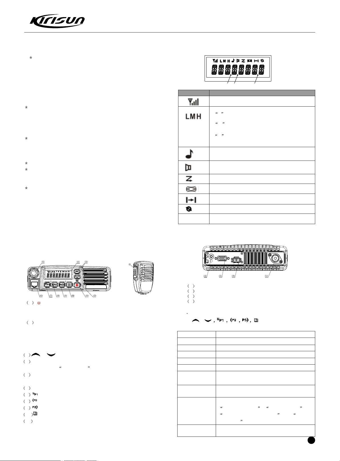
2.2 Display Screen
P1 P2 P3
Display Description
It means the receiving signal strength. 4 lines
means the strongest signal.
Transmission power level
L means the transmission of signal for the
radio at the lower power;
M means the transmission of signal for the
radio at the medium power;
H means the transmission of signal for the
radio at the high power;
Call Received indicator.
The radio receives a selective call/call alert.
Monitor State Indicator.
Scan Indicator.
Companding Indicator.
Talkaround Indicator.
Scrambler Indicator.
P2
OST Indicator.
2.3 Rear Panel
2.1 Description of External View
1 Antenna Interface
2 Power Interface
3 15-Pin Connector for accessories.
1 power button
Press this button for a long time (more than 1.5 seconds) to swith the
radio on/off.
2 LED indicator
The red indicator will light while transmitting;the green indicator will
light when it receives the carrier.
The led flashes orange on received correct DTMF/2Tonesignalling.
The red indicator flashes in the scanning process.
3 / button (programmable button)
4 LCD display screen
For details, see LCD Display .
5 Volume Control knob
To be used to adjust volume.
6 Microphone/Programming Interface
7 button (programmable button)
8 button (programmable button)
9 button (programmable button)
10 button (programmable button)
11 PTT button (on the hand microphone)
Press the PTT button first, and then speak to the microphone to
transmit the voice to the other. Release to receive.
4 External Speaker Interface
2.4 Programmable Button Function
/ can be programmed as
one of the following functions.
Buttons Function Description
0. None No function
1.Channel Up Select the next channel
2.Channel Down Select the previous channel
3.Zone Up Select the next zone
4.Zone Down Select the previous zone
5.Display Channel
Frequency
6.Display Channel
Name
7.Display Mode
Switch
8.OST Change the setup of preset CTCSS/DCS for the
current channel.
Press this button and the LCD will show the
frequency of the current channel.
Press this button and the LCD will show the
name of the current channel.
Press this button and the LCD will show
Channel Number , Channel Name ,
Zone Number, Zone Name and Channel
Frequency alternately.
3
Page 5

PT8200 SERVICE MANUAL
Buttons Function Description
Press this button to make selection among the
9.Power level
high, medium and low transmission power, and
Selection
H , M and L will be shown on the LCD
to represent the current transmission power.
Press this button to enter the Squelch Level
10.Squelch Level
Selection
Adjustment Mode first, and then press the
/ button to adjust the level. Press the button
to save the selected squelch level and
quit this mode.
11.Key lock To toggle between locking/unlocking your radio
keypad.
12.Scan Start/end the scanning function of system.
13.Nuisance
Delete
When one channel continually generated
unwanted noise,this allow you temporary remove
the channel from the current active scan.
14. Voice
Companding
Start/end the voice compression/expansion
function.
Start/end the public address function.
15. Public
Address
Press this button and the function will be actived.
Press the PTT button and speak to the micro-
-phone so that you can hear your voice through
the external speaker . Press this button once
again and return to the normal user mode.
16.Scrambler Enable or Disable voice scrambler function.
Buttons Function Description
26.Call Button 1 Sends the DTMF/2Tone code assigned to call
1 key.
27.Call Button 2 Sends the DTMF/2Tone code assigned to call
2 key.
28.Call Button 3 Sends the DTMF/2Tone code assigned to call
29.Call Button 4
30.Menu Select
/Enter
31.Horn Alert
3 key.
Sends the DTMF/2Tone code assigned to call
4 key.
To enter the menu mode or make menu
selections.
Enables the horn alert
32.Tenancy
33.Lone worker
34.Scan List Edit
35.GPS
Information View
36.VOX Level
Selection
Press this button to view tenancy remained time.
Enables lone worker function
Press this button and the radio will enter the
fast menu mode for scan list edit. For details,
see Menu Operation .
Press this button and the radio will enter the
menu mode of GPS Information Menu.
Press this button to enter the VOX Level Adju-
-stment Mode . Press / button to adjust
VOX level. Press button to save the selected
VOX level and quit this mode.
17. Home
Channel
18.Talkaround
19.VOX Selection
20. Monitor
momentary/
Call Cancel
21.Monitor/
Call Cancel
22.Squelch off
monmentary/
Call Cancel
23.Squelch off
/Call Cancel
24.Emergency
Alarm
25.Radio Call
Changes to the home channels.
Switch the radio between talkaround and
repeater mode.
Enable or disable the VOX function.
Hold this button to close CTCSS, DCS, 2Tone
/DTMF signalling according to the set data.
Loosen this button to return to the normal
operation. Press this button in the selective call
state to quit such a state.
Press this button to trigger this function and the
CTCSS, DCS, 2Tone/DTMF signalling will be
closed, so you can receive the signal that can't
be heard in the normal operation. Press this
button again to return to the normal operation.
Press this button in the selective call state to quit
such a state.
Hold this button to open the squelch. loosen this
button to return to the normal operation.
Press this button in the selective call state to quit
such a state.
Press this button to open squelch, press it again
to returm to normal operation.Press the button in
the selective call state to quit such a state
Enables the emergeney mode.
Press this button and to enter the shortcut menu
mode of Radio Call .For detailed operation,
see Menu Operation .
Chapter 3 Mode Combinations
Mode combinations
Mode Function How to access
User Mode For normal use Power on
Data Progra-
PC
-mming mode
Mode
Test Mode
Firmware Pro-
-gramming Mode
Wired Clone mode
Firmware Version
Information Display
Mode
Data programming mode:
Before leaving the factory, the radio has been set in factory. However,
due to different requirements of users, functional parameters of the
radio like working frequency, channels, CTCSS/DCS and auto scanning,
etc. should be reset. Therefore, the company has specially designed a
set of Chinese/English programming software KSP8200 with friendly
interface, convenient operation and visualized display for setting
functional parameters of the radio.
Reading and writing
frequency data and
other functions
Used to tune the radio
using the PC.
Upgrades the software
when new features are
added
Used to transfer
programming
data from one
radio to another.
Displays the firmware
version information
Receive instructions
from the PC
Receive instructions
from the PC
Receive instructions
from the PC
Hold buttons and
, and connect the
power at the same time
Hold while
connecting the power,
release to enter
the user mode.
4
Page 6
PT8200 SERVICE MANUAL
Steps for setting the functional parameters of the radio by PC are as
follows:
A.Install KSP8200 on the PC.
B.As shown in the figure below, connect the radio and the serial port
of the PC with the special programming cable KSPL-05
PC
(RS232 serial
port)
Programming
cable
KSPL-05
Radio
(MIC/Program
port)
Figure 5-1
C.Turn on the power of the PC.
D.Turn on the power of the radio.
E.Click on KSP8200 to perform the program and run KSP8200.
F.In the main menu of KSP8200, click on [Read] to read the paramete rs
of the radio into the PC; click on [Write] to write the parameters set in
the PC into the radio.
G.As required by the user, the following parameter settings can be
made with KSP8200:
1 Programmable key functions
2 Alert tone
3 Optional functions
4 2-tone/DTMF/MDC/5-tone signaling setup
5TOT
6 Emergency alarm
7 Personality template
8 Scanning function
9 Channel data
Please refer to the Help document of KSP8200 for details.
Caution:
1 Turn off the power of the radio before connection.
2 When reading data from the radio, the indicator of the radio is green,
do not press the PTT during programming; when writing data to the
radio, the indicator of the radio is red.
3 Before editing for the first time, the data should be read from the
radio and properly backed up.
4 If the edited data cannot work normally after being written into the
radio, please open the backup data and rewrite them.
5 Model Information is important information of the radio and
should not be altered.
6 Upon completion of the programming, the radio will be automatically
restarted and return to the User Mode.
Test Mode
According to Figure 5-1, connect the radio and the serial port of the
PC with the special programming cable.
Warning: Before entering the Test Mode, please first connect a highfrequency load of 50 ohm to the antenna port of the radio or connect
the radio to a comprehensive tester.
With the KSP8200 software, enter the adjustment status in the Comp-
-uter Test Mode, you can adjust the following parameters of the radio:
1)Frequency
2)Low/Med/High Power;
3)Max deviation
4)Tone deviation
5)DTMF deviation
6)MSK deviation
7)DCS balancing
8)DCS deviation
9)VOX1-level/10-level
10)CTCSS(67Hz) deviation
11)CTCSS(254.1Hz) deviation
12)Receiving sensitivity
13)9-levle/1-level Squelch open
14)9-levle/1-level Squelch close
15)RSSI
Firmware Programming Mode
The radio is equipped with FLASH ROM internally, when new fea-
-tures are announced, it can be upgraded.
1).Connect the power and enter the User Mode.
2).Run PC software KMU.
3).Connect the radio and the PC with the programming cable.
4).Select the correct serial port, select suitable baud rate according
to the actual situation, 19200 is recommended, and then click on
E.P or E.P.R for downloading. The LCD displays FIRM-
-WARE
5).Press OK to quit after the communication is successful.
6).Just repeat steps 1-5 if you want to program more radios.
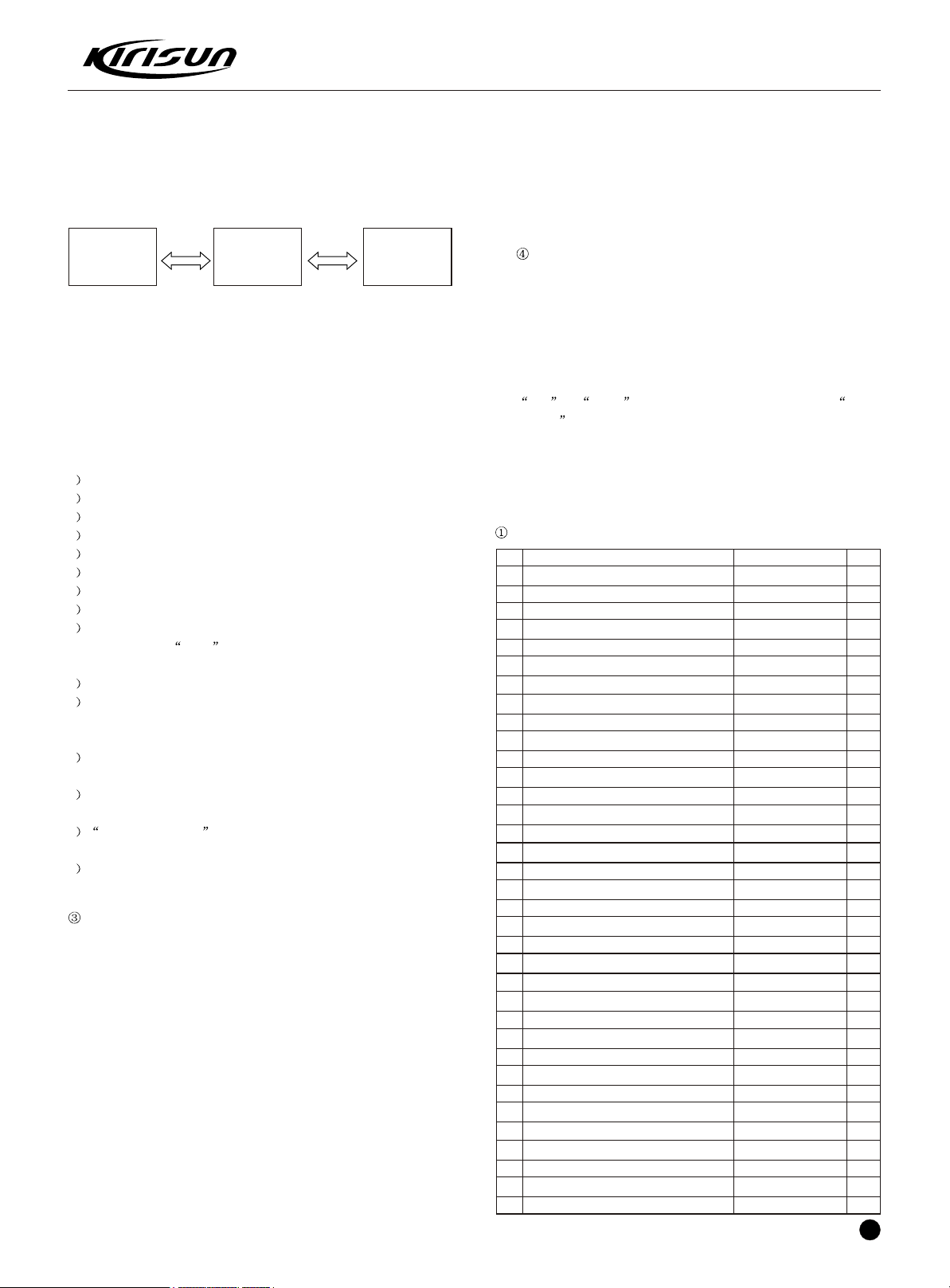
Chapter 4 Disassembly For Repair
Exploded view of the radio
6800 knot circlip
35
PT7200 coding switch nut
34
PT8200 static protection film
33
PT8200 dustproof screen for horn
32
Horn
31
B/W twisted-pair
30
PT8200 horn gasket
29
Flat cable
28
M3.0x25.0 machine screw
27
PT8200 aluminum alloy lower cover
26
PT8200 power module screen
25
M3.0x6.0 machine screw
24
Electric cable
23
PT8200 e-material of main board
22
M2.5x5.0 machine screw
21
PT8200 metal baffle
20
PT8200 plastic buckle
19
PT8200 horn hole plug
18
M3.0x10.0 sems screw
17
PT8200 antenna head
16
Silver-coated jumper cable
15
PT8200 upper/lower cover gaskets
14
PT8200 Aluminum alloy upper cover
13
PT617A VCO screen
12
PT8200 L/R gaskets of panel
11
PT8200 Lower gasket of panel
10
PT8200 Upper gasket of panel
09
M2.6x6.0 tapping screw
08
PT8200 E-material of keyboard
07
PT8200 LCD
06
PT8200 silicon key
05
PT8200 light guide
04
PT8200 lens
03
PT8200 plastic panel
02
PT8200 volume knob
01
O.
Name
N
203-006800-R26
203-007200-R08
204-008200-R08A
204-008200-R07A
121-100000-R19
120-400000-R04
204-008200-R06A
120-400000-R05
301-30250D-R01
203-008200-R02A
203-008200-R05A
301-30060G-R01
120-100000-R15
602-082001-H01
301-25050J-R01
203-008200-R04A
201-008200-R03A
202-008200-R02A
303-30100G-R01
203-008200-R03A
120-500000-R08
204-008200-R04A
203-008200-R01A
203-00617A-R01
204-008200-R03A
204-008200-R02A
204-008200-R01A
302-26060D-R01
602-08200K-H01
107-008200-R01
202-008200-R01A
201-008200-R05A
201-008200-R04A
201-008200-R01A
201-008200-R02A
Material Code
1
1
1
1
1
1
1
1
9
1
1
8
1
1
6
1
1
1
7
1
1
2
1
1
2
1
1
6
1
1
1
1
1
1
1
Quty.
5
Page 7
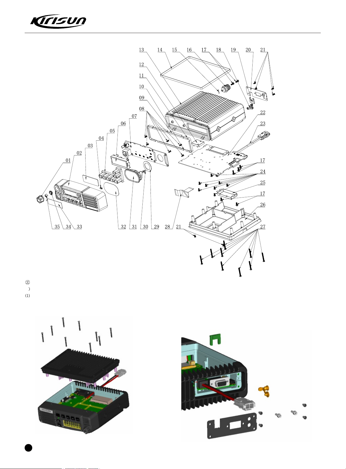
PT8200 SERVICE MANUAL
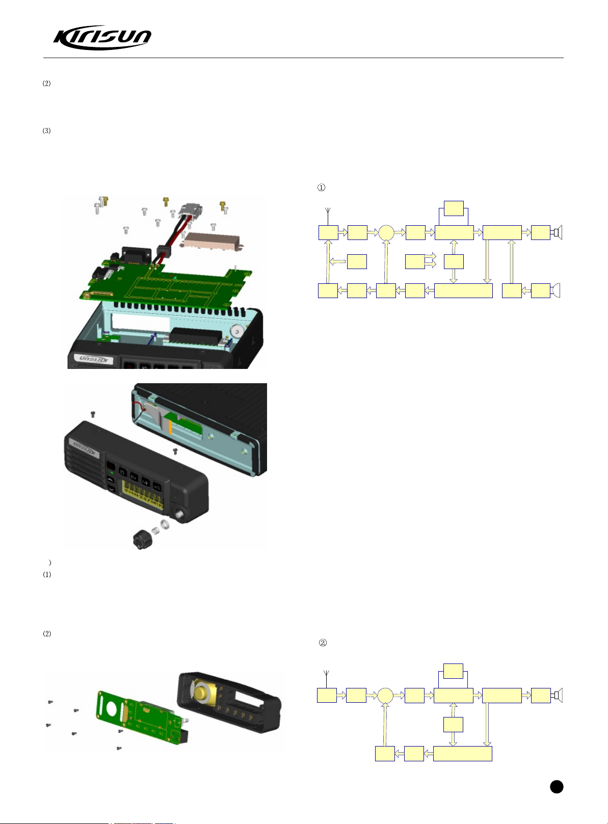
. Instruction for disassembly of the station for maintenance
1 RF-PCB Disassembly
.Release the 9 screws (M3x25) for the upper and lower covers, open
the aluminum alloy lower cover (see the left figure below).
6
Page 8
PT8200 SERVICE MANUAL
ANT SW
D31 D30
RF AMP
Q26
IF SYSTEM
TA31136
MCF
XF1 XF2
RF MAP
RA601317
MIC
AMP
MB15E03 PLL/VCO
CIRCUIT
AF AMP
TDA1519
1st
MIX
Q21
AUDIO
CONVERTER
AK2346
450KHZ
CF1 CF2
SP
MIC
AUTO
AGC
TCXO
16.8MHZ
RX/TX
SWD19½UPB1509
DIVIDE
R AMP
Q23/Q25
16.8MHZ*3
APC
CONTROL
MCU
LCD DRIVER
ALL I/O
ANT SW
D31 D30
RF AMP
Q26
IF SYSTEM
TA31136
MCF
XF1 XF2
MB15E03 PLL/VCO
CIRCUIT
AF AMP
TDA1519
1st
MIX
Q21
AUDIO
CONVERTER
AK2346
450KHZ
CF1 CF2
SP
TCXO
16.8MHZ
RX/TX
SWD19½UPB1509
16.8MHZ*3
.Release the 4 (M2.5x5) screws of the baffle and the 2 fixing screws
of the 15PIN DB socket, remove the metal baffle, the plastic buckle
and the horn hole plug (see the right figure above).
.Remove the power module screen, release the fixing screws of RF
-PCB and audio power amplifier, DC regulating IC, unplug the flat cable
and the h orn cable, welder the antenna head and the power module to
separate t hem from the RF-PCB with the electric iron, carefully remove
the RF-PCB from the aluminum ally upper cover (see the left figure
below)
After the disassembly above, you can carry out corresponding repara-
-tion and adjustment according to the actual malfunction.
Chapter 5 Circuit Description
Circuit composition
The receiving circuit adopts double conversion super-heterodyne mode.
The first IF is 49.95MHz; the second IF is 450kHz. The first local frequ-
-ency signal is provided by the phase-locked loop by controlling the V CO
circuit. The 2nd local frequency signal is provided by the 16.8MHZ
crystal triple frequency.
2 Instruction for disassembly of KEY-PCB
.Unplug the volume knob, remove the knob circlip and the switch nub,
release the 2 M2.5x5 screws for the panel to separate the panel from
the station, separate the horn cable and the horn with an electric iron,
plug out the flat cable to separate the panel with the entire station thor-
-oughly (see the right figure above)
.Release the 6 (M2.6x6) fixing screws for KEY-PCB to take out the
KEY-PCB from the plastic panel (see the figure below)
The transmission frequency is generated by the phase-locked loop by
controlling VCO circuit via the frequency dividing circuit for further
frequenc y division. The composition of the circuit is shown in the figure
above.
Transmission Protection
The power module is provided with overheating protection when
transmitti ng. When the temperature of the power module is higher than
the reference value, the communicator will switch the TX power from
high powe r to low power. Subsequently, if the temperature keeps rising,
the transmission will be stopped
Over-voltage and over-current protection of the power
When the voltage is higher than the reference value of 18V, the
communicator will automatically switch the power control and turn on
or off the power. When the receiving current is higher than the reference
value and when the polarity of the power is reverse, the F841 on the PCB
of the station will automatically cut the power supply.
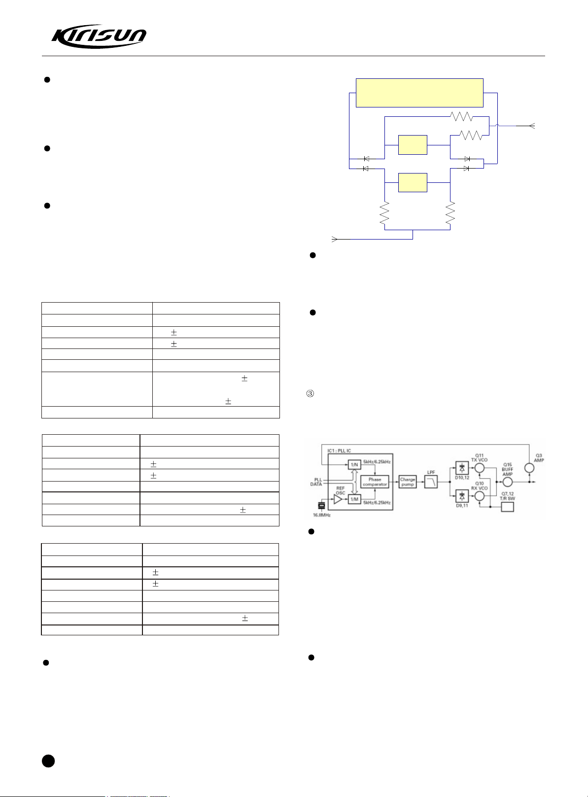
Receiving System
7
Page 9
IF demodulation TA31136
CF1
Wide
CF2
Narrow
D13
D15
Narrow
U401 PIN52
Wide
U401 PIN51
R74
R78
R73
R77
PIN 5
PIN3
1st High frequency amplifier
Signals entering the antenna enters RF amplifier (Q26) via the trans-
-mitting/receiving switching circuit (D30/D31) and the band-pass filter
(L48, L38 and variodes: D50, D26). After being amplified, the signals
are filtered by the band-pass filters (L30, L51 and the variodes: D21,
D22) before entering the 1st mixer (Q21).
1st mixer
Signals from RF amplifier and the 1st local frequency from VCO are
synthesized to generate the 1st IF of 49.95MHz. And then the 1st IF
enters the 2 single-chip crystal filter (XF1 XF2) for further elimination
of parasitic signals and then sent to the IF amplifier
IF amplifier
After being amplified by Q19, the 1st IF signal enters U102 (Ta31136).
When the signal is mixed with the 2nd local signal in U102 again, the
2nd IF signal of 450kHz is generated. Before being amplified, the 2nd
IF enters the 450kHz ceramic filter (broad: CF1, narrow: CF2) for further
elimination of unnecessary signals as well as modulation and demo-
-dulation in U102.
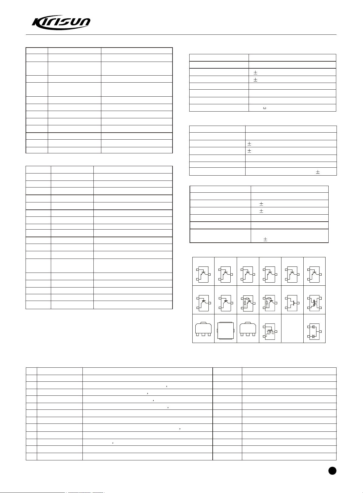
Parameters of the receiving components
Item Rated Value
Rated central frequency 49.95MHz
Pass band width 5.0kHz or higher at 3dB
35dB stop band width 20.0kHz or lower
Pulse 1.0 dB or lower
Insertion loss 5.0 dB or lower
Guaranteed attenuation 80 dB or higher at fo 1MHz
Parasitic signal: 40 dB or
higher within fo 1MHz
Terminal impedance 350 /5.5 pF
Table 1 Crystal filterXF1/XF2
Item
Rated central frequency
Pass band width
35dB stop band width
Pulse
Insertion loss
Guaranteed attenuation
Terminal impedance
Table 2 Ceramic filterCF1
Item
Rated central frequency
Pass band width
35dB stop band width
Pulse
Insertion loss
Guaranteed attenuation
Terminal impedance
Table 3 Ceramic filter Cf2
Broad/Narrow switching circuit
The broadband control port (pin 51) and narrowband control port (pin
52) of the CPU are used for switching between ceramic filters. When
the broadband control port is at high level, the ceramic filter SW diode
(D13, D15) allows the CF1 to receive broadband signals. When the
narrowband control port is at high level, the ceramic filter SW diode
(D13, D15) will allows CF2 to receive narrowband signals (The circuit
is shown in the figure below).
8
Rated Value
450kHz
6.0kHz or higher
12.5 kHz or lower
2.0 dB or lower
6.0 dB or lower
35.0 dB or higher within fo 100kHz
2.0k
Rated Value
450kHz
4.5kHz or higher
10.0 kHz or lower
2.0 dB or lower
6.0 dB or lower
60.0 dB or higher within fo 100kHz
2.0k
PT8200 SERVICE MANUAL
Audio signal system
Detection s ignals from the IF IC (U102) enters the amplifier (U601) for
adjusting the gain and be outputted to AK2346(U404) for baseband
signal processing, the output signals are inputted to the audio power
amplifier (U11) for amplification and then be outputted from the speaker.
Squelch circuit
Noise signals outputted from FM IF chip (U102) output are amplified
by the voice amplifier (Q78), the DC voltage corresponding to the noise
level is regulated and outputted, the DC voltage is then sent to the
analog port of the CPU. U102 also outputs the DC level RSSI corres-
-ponding to the IF amplifier input signals.
Phase-locked loop frequency combiner
The phase-locked loop and the voltage controlled oscillator circuit
produce the 1st local oscillation signal of the receiver and the transm-
-itting signals of the transmitter.
Phase-locked loop circuit
The frequency step of the phase-locked loop circuit is 2.5/5.0/6.25kHz.
The reference oscillator signal of 16.8MHz is divided in the chip U101
through a mixer counter to produce reference frequency of 2.5/5.0
/6.25kHz. Signals outputted from the voltage controlled oscillator(VCO)
are buffer ed and amplified via Q15 and then divided by the dual-mode
programmable counter in chip U405. Signals amplified by Q15 are
compared with phase comparators carrying reference signals with
2.5/5.0/6.25kHz in chip U101. Signals output from the phase compar-
-ator controls the voltage to enter a low-pass filter and to control the
oscillation frequency through the voltage controlled oscillator.
Voltage controlled oscillator
The RF rate is generated via Q11 in the transmission mode, the recei-
-ving frequency is generated via Q10 in the receiving mode. The control
signals ge nerate voltage via the phase comparator to the variode (D10
and D12 in the transmission mode, D9 and D11 in the receiving mode).
In the receiving mode, Q12 is cut and Q7 is connected, in the transm-
-ission mode, Q12 is connected and Q7 is disconnected. Output signals
from Q10 and Q11 are amplified by Q15 and sent to U405 frequency
divider.
Page 10
PT8200 SERVICE MANUAL
ANT SW
D31 D30
RF MAP
RA601317
MIC
AMP
MB15E03 PLL/VCO
CIRCUIT
AUDIO
CONVERTER
AK2346
MIC
AUTO
AGC
TCXO
16.8MHZ
RX/TX
SWD19½UPB1509
DIVIDE
R AMP
Q23/Q25
APC
CONTROL
ANT
switch
D31 D30
Power
amplifier
RA601317
RX/TX
switch
D19
Drive
amplifier
Q23/Q25
Low-pass
filter
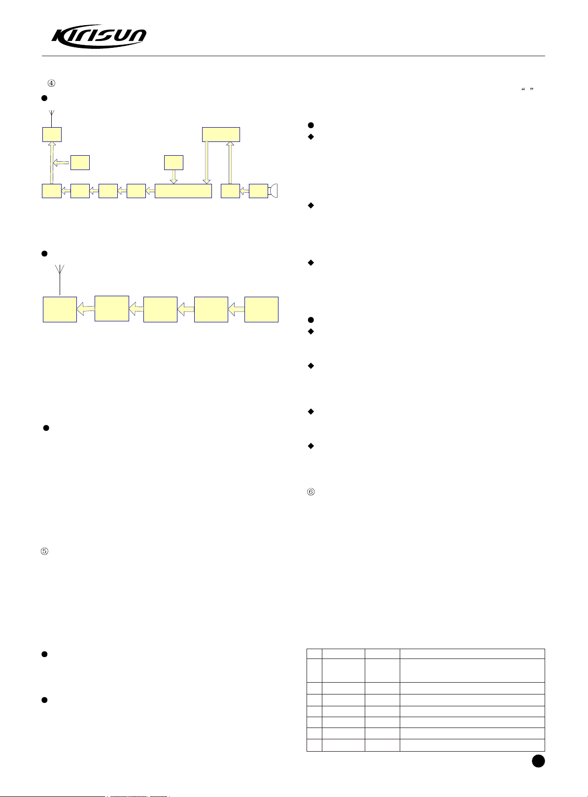
Transmitting system
Block diagram
he transmitting circuit directly produces and amplifies the required
frequency and conducts frequency modulation for carrier signals via
the variode.
Transmitting driving power amplifier circuit
Transmitting signals from the voltage controlled oscillator are amplified
through the frequency division and transmission/receiving selector
diode(D19) and the driving amp lifier(Q23 and Q25), thus providing the
power moduleRA601317M/(RA554047M) with a special level. The
amplified signals then enter a low-pass filter. The low-pass filter
eliminates unnecessary high-frequency harmonics and the acquired
signals enter the antenna terminal.
Auto power control circuit
The auto transmitting power control (APC) circuit adopts the diodes
(D34, D36) to detect part of the power module outputs and provide
control voltage for U202. Through comparison with the reference
voltage outputted from MCU input, U202 generates the error voltage
and outputs from pin 7 of U202 to control the power amplifier Ra6013
17M and transmits output power stable. The composition of the auto
power cont rol circuit is for preventing over current of the power module
due to the fluctuation of the load of the antenna terminal and stabilizing
the output voltage and temperature change of transmission.
Control circuit
The CPU is provided with the following tasks:
1)Embedded Flash Rom, including the control program
2)Controlling the receiving circuit
3)Controlling the transmitting circuit
4)Controlling the display circuit
5)Various function control circuits
6)Communicating data with external devices
Storage circuit
The radio is provided with a 256k-bit EEPROM (U402) for storing pro-
-gramming or testing data.
Display circuit
The display circuit consists of the CPU (U401), the LCD component,
LED and other components. When the communicator is busy and the
LEDG cable is at high level, Q4 is connected and the green LED (D11)
is on. When transmitting, the LEDR cable is at high level, Q8 is conne-
-cted and the red LED (D12) is on, Led D1 to D4 provide the LCD back-
-light, which is on when operating the radio. The LCD is in the *
shape and can display up to 8 digits or letters.
Encoding
CTCSS/DCS:
Outputting CTCSS/DCS signals from the CPU(U401); one channel is
outputted from PIN24 via the low-pass filter and mixed with audio
signals and the external pin DI line, then inputted to the VCO for mod-
-ulation; the other channel is outputted from PIN28 output to TCXO(XI)
for modulation.
2-TONE/5-TONE/DTMF:
PIN2 of the CPU outputs 2-TONE/5-TONE/DTMF coding signals, which
are inputted to the baseband processing IC (U404) via low-pass CR
filter for filtration and deviation control and then sent to the VCO for
modulation.
MSK:
MSK signal is generated by U404, through filtration and frequency
deviation control, it is outputted from PIN7 and sent to VCO for
modulation.
Decoding
CTCSS/DCS
CTCSS/DCS signals are processed and amplified by U403 filter and
sent to PIN92 of MCU for filtration and decoding.
2-TONE/5-TONE
2-TONE/5-TONE signals are filtered and amplified by U503 and receive
waveform transformation via U801 (sine wave into square wave) and
then sent to PIN3 of MCU for filtration and decoding.
DTMF
DTMF signals are filtered and amplified by U503 and sent to PIN2 of
U803 (HT9172) for decoding.
MSK
MSK signal s are filtered, amplified and decoded by U404 and then s ent
to MCU for MSK signal processing and control.
Power circuit
When the POWER switch on the front panel is pressed, the port
connecting the POWER on the display board and the terminal pins of
the CPU is at low level, Pin 80 (SBC) of the CPU is as high level, Q34
is connected, SB SW (Q42) is connected and supplying power to the
communicator (SB). This circuit is provided with the over-voltage prot-
-ection circuit. If 17V or higher voltage is provided to the power cable,
D839 will be connected and supply voltage to the base of Q38. This
voltage makes Q38 connected and Q34 and SB disconnected.
Chapter 6 Semiconductor Data
Processor: M30620
Pin
1
Port Name
PC/TV
In/Out
O
Function
Transmit power and receive sensitivity
adjusting voltage output
2
3
4
5
6
7
DTMF
HSDI
EEP DAT
EEP CLK
BYTE
CNVSS
O
I
I/O
O
I
I
DTMF/2Tone/5Tone/Beep output
Hi-speed data input
EEPROM data input/ output
EEPROM clock output
GND
GND
9
Page 11
PT8200 SERVICE MANUAL
Pin Port Name In/Out Function
8
BSHIFT
9
EXT SPK
10
RESET
11
XOUT
12
VSS
13
XIN
14
VCC
15
NMI
16
DTMF DV
17
RDT
18
TCLK
19
SCLK
20
FreqStab
21
TDATA
22
SideToneVol
23
DI/O
24
CTCSSVCO
25
DIR
26
HNC
27
-
28
CTCSS TCXO
29
TXD1
30
RXD1
31
CLK1
32
RTS1
33
TXD0
34
RXD0
35
RX W/N
36
TX W/N
37
RX SW
38
TX SW
39
HOLD
40
PLL UL
41
PLL STD
42
PLL DAT
43
PLL CLK
44
RD
45
PLL T/R
46
-
47
-
48
Au2
49
Aux1
50
PTT C
51
W/N R1
52
W/N R2
53
AFCON
54
RX MUTE
55
PSW
56
LCD RST
57
LCD BLC
58
LCD DAT
59
LCD WR
60
VCC
61
LCD RD
62
VSS
63
LCD CS
Clock selection control
O
External SPK conversion
O
CPU reset input
I
CPU clock output
O
GND
CPU clock input
I
+5v
+5v
I
DTMF decoding detection
I
AK2346 MSK signal receiving symbol
I
and frame detection input
AK2346 MSK data transmission clock
I
input
AK2346 serial clock output
O
Frequency control output
O
AK2346 MSK data output
O
Side tone volume control output
O
AK2346 serial data input output
I/O
CTCSS/DCS output to the VCO
O
AK2346 serial data input/ output control
O
Speaker alarm control output
O
NC
CTCSS/DCS output TCXO (PWM)
O
PC serial data output
O
PC serial data input
I
NC
NC
GPS serial data output
O
GPS serial data input
I
Receive broad/narrow band switch
O
Transmit broad/narrow band switch
O
Receiving VCO switch
O
Transmitting VCO switch
O
GND
PLL loss of lock detection input
I
PLL enabling control output
O
PLL serial data output
O
PLL clock output
O
NC
PLL transmitting/receiving switch output
O
NC
NC
Programmable auxiliary input/output
I/O
Programmable auxiliary input/output
I/O
Intermediate PTT control output
O
Receive IF broad/narrow band switch
O
Receive IF broad/narrow band switch
O
Audio power amplifier control output
O
Receive mute switch
O
Power key input
I
LCD reset control
O
LCD backlight control output
O
LCD serial data input/ output
I/O
LCD writing clock output
O
+5v
LCD reading clock output
O
GND
LCD chip selection signal output
O
Pin Port Name In/Out Function
64
KEY BLC
65
P4
66
P3
67
P2
68
P1
69
Down Key
70
Up Key
71
R LED
72
G LED
73
SideToneFixed
74
MBLC
75
MIC DAT
76
HOOK
77
PTT
78
MinVol
79
Int Mic Mute
80
8T C
81
8R C
82
SBC
83
DTMF D3
84
DTMF D2
85
DTMF D1
86
DTMF D0
87
NC
88
TEMP
89
RSSI
90
BUSY
91
VOX
92
TI
93
DTMF IN
94
AVSS
95
PA C
96
VREF
97
AVCC
98
IGN
99
Ext Mic Mute
100
HPF PC
Front panel keypad backlight control
O
output
P4 key
I
P3 key
I
P2 key
I
P1 key
I
Down key
I
Up key
I
Transmit LED control
O
Receive LED control
O
Fixed side tone volume control
O
MI keypad backlight control
O
MIC keypad serial data
I/O
Hangup signal input
I
PTT input
I
Min. Volume control
O
MIC mute switch
O
8T power control
O
8R power control
O
SB power control output
O
DTMF receiving signal input
I
DTMF receiving signal input
I
DTMF receiving signal input
I
DTMF receiving signal input
I
NC
I
Temperature detection input
I
Receiving field intensity signal input
I
Squelch level detection input
I
VOX voltage detection input
I
CTCSS/DCS decoding input
I
DTMF decoding input
I
GND
Speech speaker control output
O
+5v
+5v
Ignition sensor input
I
External MIC mute switch
O
High-pass filter switch
O
Chapter 7 Description of Components
Functional description of semiconductor device
Item
U101
U202
U102
IC404
U501
U11
U402
U401
U305
Q23
Q25
Q16
Q20
Q14
Model
MB15E03
TC75W51
TA31136
AK2346
TC75W51FU
TDA1519C
AT24C256
M3062LFGPGP
PST9140NR
2SC3357
2SC3357
2SC4226
2SC4627
2SC4617
Function Description
Phase-locked loop chip
APC driver
IF demodulation
Baseband audio processor
MIC amplifier
AF Power AMP
EEPROM
MCU
Voltage detector reset
Transmitter1st amplifier
Transmitter 2nd amplifier
VCO buffering amplifier
VCO buffering amplifier
VCO power filter
10
Page 12
PT8200 SERVICE MANUAL
3SK318
M: YB-
G1
G2
D
S
G
S
D
CC
C
C
B
B
B
B
E
E
E
E
G
D
S
2SK18 24
Mark: B1
2SC5108
M: MC
C
B
E
M: R24
2SC3356
C
B
E
2SC4617
C
B
E
C
B
E
2SC473 8
KTC4082
C
B
E
2SC1623
M: L6
KTA1298
DTC144EE
M:16
GND
IN
OUT
HT7150-1
RD01MUS1
D
G
S
S
RD07MVS1
RDA0002
1
2
3
DA221
M: K
2SK308NV
DTA144EE
C
B
E
FMMT591
GSD
Item Model Function Description
Q78
U201
2SC2412K
RA601317M
Noise amplifier
Transmitting final power
amplifier IC
Q70
Q423
DTA144EE
DTA144EEAPC output
Wide/narrow band switch
APC output switch
switch
Q21
Q26
Q19
Q605
Q701
Q30/Q29
Q7
Q12
3SK3181st mixer
3SK318RF amplifier
2SC46271st IF amplifier
KRC102SAF Mute
2SC4617LED driver
RAC102S8T/8R switch
2SJ243TX switch
2SJ243RX switch
1st mixer
RF amplifier
1st IF amplifier
AF Mute
LED driver
8T/8R switch
TX switch
RX switch
Diode functional description
Item
D30
D19
D34/D36
D31/D32
D501/D68
D10
D12
D9
D11
D308
DD1/D902
D6
D16
Model
MA4PH633
DAN235
MA742
MA4P1250
MA742
ISV325
ISV325
ISV278
ISV325
ISV325
HZU5ALL
MA2S111
MA2S111
Function Description
Transmitter antenna switch diode
VCO output switch
Power detection diode
Receiver antenna switch diode
AGC control diode
Transmit VCO oscillation varicap
Transmit VCO oscillation varicap
VCO adjust diode
Receive VCO oscillation varicap
Receive VCO oscillation varicap
Output voltage-limiting diode
Loss of lock detection diode
VCO power supply strain
accelerate diode
D18
D70
D13/D15
D21/D22
D26/D50
Ma742
LED red and green
DAN222
ISV305
ISV305
Noise demodulation
Transmit receive indication
Wide narrowband filter control diode
Receive band pass varicap
Receive band pass varicap
Characteristic of XF1/XF2 crystal filter
Item
Nominal center frequency
Transmission band width
40dbstop band width
Ripple
Insertion loss
Ensure attenuation
Terminal impedance
Rated Value
49.95mhz
7.5khz or higher, but within 3db
20.0khz or lower
1.0db or lower
3.0db or lower
80db or higher, but between fo-910khz
1.5k /6pf
Performance and parameter cf1 CF1 LTWC450F
Item
Nominal center frequency
6db band width
50db band width
Ripple
Insertion loss
Ensure attenuation
Rated value
450khz
5.0khz or higher
13.5khz or lower
3.0db or lower
7.0db or lower
45.0db or higher, but between f0 100khz
Performance and parameter CF2 LTWC450G
Item
Nominal center frequency
6Db band width
50dB band width
Ripple
Insertion loss
Guaranteed attenuation
Rated Value
450kHz
3.5kHz or higher
12kHz or lower
3.0dB or lower
7.0dB or lower
45.0dB or higher, between
f0 100kHz
Semiconductor device packaging sketch
PT8200 mainboard BOM / 136-174MHz
No Material Serial No. Name/Spec. Quantity Installation Positon
6PM7-1943-HMB
1
1IS1-UPB1509GV
2
1IME-AT24C256N10SI27
3
1MR3-RA60H1317M
4
1IS3-L7808CV
5
6
7
8
9
10
11
12
1IS1-PST9140NR
1IS3-TDA1519C
1IS1-TA31136FN
1IS1-TA75W01FU
1IS1-AK2346
1IS1-MB15E03SL
1IS1-TC75W51FU
PT8200PCB ,PT8200V-080430.PCB,ROHS
Frequency demultiplier/ UPB1509GV ROHS
Memory IC / AT24CL256AN ROHS
Power module / RA60H1317M ROHS
In-line regulator IC / L7808CV,TO-220 ROHS
Restoration IC / PST9140NR,ROHS
Audio power amplifier / TDA1519C,SIL9,ROHS
IF(FM)demodulationIC / TA31136FN,SSOP ROHS
Operational amplifier / TA75W01FU,ROHS
IC / AK2346 ROHS
PLL IC / MB15E03SL,PLL,16-PIN,SSOP,ROHS
Operational amplifier / TC75W51FU,SSOP8-P-0.65,ROHS
1
1
1
1
1
1
1
1
1
1
1
5
U405
U402
U201
U302
U305
U11
U102
U202
U404
U101
U601, U403, U501, U503, U801
11
Page 13
PT8200 SERVICE MANUAL
No Material Serial No. Name/Spec. Quty Installation Positon
1IS1-XC62FP3502PR
13
1IS1-HT9172
14
1IP1-M16CM3062LFGPGP
15
1IS1-NJM78L05UA
16
1DZ1-02DZ18-X
17
103-00MA77-R01
18
1DS1-DA221
19
1DS1-MA742
20
1DS1-1SS355
21
1DV1-1SV278
22
1DV1-1SV305
23
1DV1-1SV325
24
1DS1-MA4PH633
25
1DS1-MA2S111
26
103-AP1250-R01
27
1DS1-DAN222
28
1DS1-DAN235E
29
1DZ1-HZU5ALL
30
1DZ1-HZU5CLL
31
1DG1-DSM3MA1
32
1TT1-DTA123JE
33
1TT1-DTA144EE
34
1TT1-DTC114EE
35
1TT1-DTC144EE
36
1TT1-KRC102S
37
1TT1-KRC404RTK
38
1TT1-2SA1641-S
39
1TT1-2SA1745-6
40
1TT1-2SA1774-R
41
1TT1-2SA1832-GR
42
1TT1-2SC2412K-Q
43
1TT1-2SC3357
44
1TT1-2SC4116-GR
45
1TT1-2SC4226-R24
46
1TT1-2SC4617-S
47
1TT1-2SC4649-N
48
1TT1-2SC4738-GR
49
1TT1-KTA1664-Y
50
1TF1-2SJ243
51
1TF1-2SK508NV-K52
52
1TF1-3SK318
53
1TF1-2SK1824
54
3SJ3-OVR-SH-209L
55
5FT3-LTM450FW
56
5FT3-LTM450GW
57
5FC3-S49M95-UM5
58
2RS1-16-000O
59
2RS1-16-100J
60
Regulator IC / XC62FP3502PR,SOT-89,ROHS
DTMF decode IC/ HT9172,sop, ROHS
CPU / M16C-M3062LFGPGP,FLASH,100P6Q-A,ROHS
Regulator IC / NJM78L05UA ROHS
Chip regulator diode / 02DZ18(X.Y),ROHS
Chip HF on-off diode / MA77,0805,ROHS
Chip array diode / DA221(ROHM)
Chip on-off diode / MA742(PANASONIC),ROHS
Chipdiode / 1SS355B,ROHS
Chip variable capacitor diode / 1SV278,ROHS
Chip variable capacitor diode / 1SV305,ROHS
Chip variable capacitor diode / 1SV325,ROHS
Chipdiode/ MA4PH633 ROHS
Chip on-off diode / 0603,MA2S111(PANASONIC),ROHS
Chipdiode / MA4P1250-1072T,ROHS
Chip on-off diode / DAN222,(ROHM),ROHS
Chipdiode / DAN235E,ROHS
Chip regulator diode / HZU5ALL(HITACHI),ROHS
Chip regulator diode / HZU5CLL,ROHS
Chipdiode / DSM3MA1,ROHS
Chip triode / DTA123JE(ROHM),ROHS
Chip triode / DTA144EE(ROHM),ROHS
Chip triode / DTC114EE(ROHM),ROHS
Chip triode / DTC144EE(ROHM),ROHS
Chip triode / KRC102S,ROHS
Chip triode / KRC404RTK,ROHS
Chip triode / 2SA1641(S.T),ROHS
Chip triode / 2SA1745(6,7),ROHS
Chip triode / 2SA1774(Q R) ROHS
Chip triode / 2SA1832(G R),ROHS
Chip triode / 2SC2412K,ROHS
Chip triode / 2SC3357 ROHS
Chip triode / 2SC4116-GR ROHS
Chip triode / 2SC4226(R24),ROHS
Chip triode / 2SC4617(S)(ROHM),ROHS
Chip triode / 2SC4649(N,P), 2SC4627 ROHS
Chip triode / 2SC4738(GR),AF,AMPLIFIER(TOSHIBA),ROHS
Chip triode / KTA1664(Y),ROHS
Chip FET (field-effect transistor) / 2SJ243,ROHS
Chip FET / 2SK508NV(K52),ROHS
Chip FET / 3SK318,ROHS
Chip FET / 2SK1824,ROHS
Plug-in Relay / G5V-1,Work voltage 9V/DC,ROHS
Plug-in porcelain filter / LTM450FW,450kHz 7kHz,ROHS
Plug-in porcelain filter / LTM450GW,450kHz 5kHz,ROHS
Plug-in IF filter / 49.95MHz 7.5KHz,U-5*2,ROHS
Chip resistor / 0603,0R 5%,ROHS
Chip resistor / 0603,10R 5%,ROHS
U304
1
U803
1
U401
1
U301, U303, U333
3
D839
1
DD2
1
D23
1
D65, D66, D18, D68, D34, D36, D501
7
D58, D558, D27, D518
4
D14
1
D21, D22, D26, D50
4
D9, D10, D11, D12
4
D30,
1
D16, D6
2
D31, D32
2
D13, D15
2
D19
1
D7, D921
2
DD1
1
D838
1
Q85
1
Q70
1
Q402, Q482, Q682, Q472
4
Q403, Q423
2
Q29, Q30, Q34, Q605
4
Q38
1
Q42
1
Q31
1
Q94
1
Q4
1
Q78
1
Q23, Q25
2
Q501, Q531
2
Q15
1
Q87, Q88, Q89, Q14
4
Q20, Q3, Q6, Q19
4
Q5
1
Q33
1
Q7, Q12
2
Q11, Q10
2
Q21, Q26
2
Q50, Q51, Q52, Q53, Q550, Q752, Q711
7
K101, K102
2
CF1
1
CF2
1
XF1, XF2
2
L50, R32, R44, R277, R316, R505, R347,
20
R352, R353, R354, R355, R563, R358, R413,
3
R559, R5, R315, R346, R887, R367,R15, R112,
R288
2RS1-16-101J
61
2RS1-16-102J
62
Chip resistor / 0603,100R 5%,ROHS
Chip resistor / 0603,1K 5%,ROHS
R107, R133, R167, R289, R298, R88,
13
R239, R502, R616, R159, R160, R150, R236
R172, R181, R853, R815, R827, R809,
47
R814, R10, R281, R808, R689, R664,
R682, R11, R13, R385, R386, R387, R388,
R389, R667, R681, R683, R684, R685, R686,
R687, R688, R970, R971, R984, R988, R989,]
R663, R169, R275, R384, R412, R627, R4,
12
Page 14

PT8200 SERVICE MANUAL
No Material Serial No. Name/Spec. Quty Installation Positon
R46, R290, R869, R235, R117, R843, R7
R216, R60, R243, R251, R293, R414, R418,R309, R34,R39,
63 109-060103-R01
2RS1-16-104J
64
2RS1-16-105J
65
2RS1-16-121J
66
2RS1-16-122J
67
2RS1-16-123J
68
2RS1-16-124J
69
2RS1-16-151J
70
2RS1-16-152J
71
2RS1-16-153J
72
2RS1-16-154J
73
2RS1-16-183J
74
2RS1-16-184J
75
2RS1-16-204J
76
2RS1-16-220J
77
2RS1-16-221J
78
2RS1-16-222J
79
2RS1-16-223J
80
2RS1-16-224J
81
2RE1-16-2402
82
2RS1-16-271J
83
2RS1-16-272J
84
2RS1-16-273J
85
2RS1-16-274J
86
2RS1-16-330J
87
2RS1-16-331J
88
2RS1-16-332J
89
2RS1-16-333J
90
2RS1-16-334J
91
2RS1-16-392J
92
2RS1-16-394J
93
2RS1-16-470J
94
2RS1-16-471J
95
2RS1-16-472J
96
2RS1-16-473J
97
2RS1-16-474J
98
2RS1-16-513J
99
2RS1-16-561J
100
2RS1-16-562J
101
2RS1-16-563J
102
2RS1-16-623J
103
2RS1-16-682J
104
2RS1-16-683J
105
2RE1-16-6803
106
2RS1-16-821J
107
2RS1-16-822J
108
2RS1-16-823J
109
2RS1-16-913J
110
2RS1-20-220J
111
2RS1-50-151J
112
2RS1-50-220J
113
Chip resistor / 0603,10K 5%,ROHS
Chip resistor / 0603,100K 5%,ROHS
Chip resistor / 0603,1M 5%,ROHS
Chip resistor / 0603,120R 5%,ROHS
Chip resistor / 0603,1.2K 5%,ROHS
Chip resistor / 0603,12K 5%,ROHS
Chip resistor / 0603,120K 5%,ROHS
Chip resistor / 0603,150R 5%,ROHS
Chip resistor / 0603,1.5K 5%,ROHS
Chip resistor / 0603,15K 5%,ROHS
Chip resistor / 0603,150K 5%,ROHS
Chip resistor / 0603,18K 5%,ROHS
Chip resistor / 0603,180K 5%,ROHS
Chip resistor / 0603,200K 5%,ROHS
Chip resistor / 0603,22R 5%,ROHS
Chip resistor / 0603,220R 5%,ROHS
Chip resistor / 0603,2.2K 5%,ROHS
Chip resistor / 0603,22K 5%,ROHS
Chip resistor / 0603,220K 5%,ROHS
Chip resistor / 0603,24K 1%,ROHS
Chip resistor / 0603,270R 5%,ROHS
Chip resistor / 0603,2.7K 5%,ROHS
Chip resistor / 0603,27K 5%,ROHS
Chip resistor / 0603,270K 5%,ROHS
Chip resistor / 0603,33R 5%,ROHS
Chip resistor / 0603,330R 5%,ROHS
Chip resistor / 0603,3.3K 5%,ROHS
Chip resistor / 0603,33K 5%,ROHS
Chip resistor / 0603,330K 5%,ROHS
Chip resistor / 0603,3.9K 5%,ROHS
Chip resistor / 0603,390K 5%,ROHS
Chip resistor / 0603,47R 5%,ROHS
Chip resistor / 0603,470R 5%,ROHS
Chip resistor / 0603,4.7K 5%,ROHS
Chip resistor / 0603,47K 5%,ROHS
Chip resistor / 0603,470K 5%,ROHS
Chip resistor / 0603,51K 5%,ROHS
Chip resistor / 0603,560R 5%,ROHS
Chip resistor / 0603,5.6K 5%,ROHS
Chip resistor / 0603,56K 5%,ROHS
Chip resistor / 0603,62K 5%,ROHS
Chip resistor / 0603,6.8K 5%,ROHS
Chip resistor / 0603,68K 5%,ROHS
Chip resistor / 0603,680K 1%,ROHS
Chip resistor / 0603,820R 5%,ROHS
Chip resistor / 0603,8.2K 5%,ROHS
Chip resistor / 0603,82K 5%,ROHS
Chip resistor / 0603,91K 5%,ROHS
Chip resistor / 0805,22R 5%,ROHS
Chip resistor / 2010,150R 5%,ROHS
Chip resistor / 2010,22R 5%,ROHS
27
R419, R812, R816, R877, R392, R600, R101, R106, R727,
R743, R767,R768, R199, R576, R292, R307, R8
17
R188, R258, R503, R506, R504, R657, R256, R204, R245,
R509, R510, R810, R811, R238, R244, R852, R20
4
R525, R526, R527, R561
3
R174, R148, R208
1
R103
5
R562, R539, R699, R467, R700
5
R72, R479, R480, R481, R628
1
R99
5
R201, R252, R12, R56, R55
3
R308, R249, R606
5
R108, R645, R879, R508, R241
5
R540, R541, R542, R543, R488
2
R530, R531
2
R319, R320
1
R300
3
R98, R317, R153
5
R175, R185, R318, R626, R197
13
R73, R74, R291, R297, R301, R302, R304, R305, R698, R77,
R78, R268, R37
3
R40, R545, R149
2
R551, R552
2
R158, R165
5
R51, R314, R507, R67, R87
8
R283, R553, R554, R555, R712, R533, R617, R813
1
R560,
2
R296, R224
3
R163, R221, R233
2
R130, R362
6
R326, R449, R450, R676, R217, R348
3
R146, R266, R247
1
R321
2
R537, R538
2
R203, R186
5
R36, R132, R154, R448, R558
19
R94, R102, R211, R325, R331, R332, R124, R334, R666,
R729, R728, R322, R242, R265, R858, R3, R333, R420, R803
18
R61, R70, R254, R255, R282, R248, R246, R147, R164, R374,
R376, R416, R417, R826, R373, R711, R111, R511
2
R476, R477
1
R544
1
R391
4
R38, R393, R394, R395
3
R516, R517, R218
3
R267, R250, R263
2
R397, R532
2
R453, R383,
3
R536, R546, R564
2
R299, R452
1
R478
4
R382, R534, R179, R306
2
R482, R483
2
R213, R205
1
R257
1
R198
13
Page 15

PT8200 SERVICE MANUAL
No Material Serial No. Name/Spec. Quty Installation Positon
114
2RS1-50-471J
115
2RV3-22ZR-10D
116
3FW1-42932-3023201
2CC1-16-C0G500-100D
117
2CC1-16-C0G500-101J1
118
119
2CC1-16-X7R500-102K
Chip resistor / 2010,470R 5%,ROHS
Plug-in voltage-dependent resistor / 10D220 ROHS
Chip Fuse / 433003,3A/32V,1206 ROHS
Chip capacitor / 0603,10P 5%,50V,C0G,ROHS
Chip capacitor / 0603,100P 5%,50V,C0G,ROHS
Chip capacitor / 0603,1000P 10%,50V,X7R,ROHS
1
R262
1
DD3
1
F841
5
C75, C170, C150, C253, C742
C174, C229, C330, C331, C332, C367, C755
7
79
C38, C83, C184, C187, C188, C194, C197,
C198, C120, C128, C201, C204, C209, C210,
C211, C213, C42, C136, C143, C221, C228,
C232, C239, C251, C48, C49, C146, C154,
C252, C264, C279, C303, C308, C55, C94,
C159, C162, C309, C310, C320, C324, C339,
C344, C102, C168, C169, C358, C364, C365,
C369, C394, C537, C217, C176, C179, C662,
C677, C735, C222, C707, C708, C709, C710,
C711, C712, C713, C714, C715, C716, C717,
C718, C719, C335, C404, C652, C2, C650,
C18, C560
12
2CC1-16-X7R500-103K
120
Chip capacitor / 0603,0.01uF 10%,50V,X7R,ROHS
C576, C577, C881, C882, C618, C638, C242,
C21, C33, C925, C556, C557,
45
2CC1-16-X7R500-104K1
121
Chip capacitor / 0603,0.1uF 10%,50V,X7R,ROHS
C71, C88, C271, C275, C286, C314, C329,
C17, C26, C119, C336, C593, C356, C387,
C34, C37, C558, C888, C28, C127, C135,
C402, C403, C405, C80, C812, C895, C155,
C165, C411, C412, C413, C414, C415, C208,
C237, C416, C417, C418, C807, C811, C333,
C269, C256, C626
C218, C311, C317, C860, C533, C536, C539,
2CC1-16-X7R100-105K
122
Chip capacitor / 0603,1uF 10%,50V,X7R,ROHS
19
C541, C542, C543, C544, C545, C546, C548,
C549, C705, C393, C406, C547
112-063120-R01
123
112-063121-R01
124
112-063123-R01
125
112-063150-R01
126
112-063151-R01
127
112-063180-R01
128
112-063181-R01
129
112-063182-R01
130
112-063200-R01
131
112-063220-R01
132
112-063222-R01
133
134
112-063223-R01
112-063224-R01
135
112-063270-R01
136
112-063271-R01
137
112-063273-R01
138
112-0632R0-R01
139
112-063300-R01
140
112-063330-R01
141
112-063333-R01
142
112-063334-R01
143
112-063392-R01
144
112-0633R0-R01
145
112-063430-R01
146
112-063470-R01
147
112-063471-R01
148
Chip capacitor / 0603,12P 5%,50V,C0G,ROHS
Chip capacitor / 0603,120P 5%,50V,C0G,ROHS
Chip capacitor / 0603,0.012uF 10%,50V,X7R,ROHS
Chip capacitor / 0603,15P 5%,50V,C0G,ROHS
Chip capacitor / 0603,150P 5%,50V,C0G,ROHS
Chip capacitor / 0603,18P 5%,50V,C0G,ROHS
Chip capacitor / 0603,180P 10%,50V,X7R,ROHS
Chip capacitor / 0603,1800P 10%,50V,X7R,ROHS
Chip capacitor / 0603,20P 5%,50V,C0G,ROHS
Chip capacitor / 0603,22P 5%,50V,C0G,ROHS
Chip capacitor / 0603,2200P 10%,50V,X7R,ROHS
Chip capacitor / 0603,0.022uF 10%,50V,X7R,ROHS
Chip capacitor / 0603,0.22uF+80%--20%,16V,Y5V,ROHS
Chip capacitor / 0603,27P 5%,50V,C0G,ROHS
Chip capacitor / 0603,270P 10%,50V,X7R,ROHS
Chip capacitor / 0603,0.027uF 10%,16V,X7R,ROHS
Chip capacitor / 0603,2P 0.25P,50V,C0G,ROHS
Chip capacitor / 0603,30P 5%,50V,C0G,ROHS
Chip capacitor / 0603,33P 5%,50V,C0G,ROHS
Chip capacitor / 0603,0.033uF 10%,16V,X7R,ROHS
Chip capacitor / 0603,0.33uF 10%,50V,X7R,ROHS
Chip capacitor / 0603,3900P 10%,50V,X7R,ROHS
Chip capacitor / 0603,3P 0.25P,50V,C0G,ROHS
Chip capacitor / 0603,43P 5%,50V,C0G,ROHS
Chip capacitor / 0603,47P 5%,50V,C0G,ROHS
Chip capacitor / 0603,470P 10%,50V,X7R,ROHS
2
C216, C163
1
C620
1
C623
2
C189, C300
1
C606
1
C141
1
C78
1
C116
3
C408, C809, C810
4
C407, C25, C685, C506
2
C922, C500
5
C142, C147, C427, C430, C559
3
C602, C622, C575
6
C114, C177, C202, C247, C492, C493
1
C81
C605
1
4
C85, C122, C186, C273
2
C685, C506
3
C138, C363, C483
9
C432, C433, C434, C781, C501, C595, C596,
C597, C615
1
C160
1
C15
5
C118, C86, C97
C266
1
C563, C565, C74
3
C584, C630, C632, C771, C848, C927, C505,
40
, C100, C361
C515, C16, C69, C79, C82, C101, C108, C109,
C111, C112, C157, C230, C290, C295, C298,
14
Page 16

PT8200 SERVICE MANUAL
No Material Serial No. Name/Spec. Quty Installation Positon
149
112-063472-R01
150
112-063473-R01
151
112-063474-R01
152
112-0634R0-R01
153
112-063560-R01
154
112-063561-R01
155
112-063562-R01
156
112-0635R0-R01
157
112-063680-R01
158
112-063683-R01
159
112-0636R0-R01
160
112-0637R0-R01
161
112-063820-R01
162
112-0638R0-R01
163
112-063R50-R01
164
112-063R75-R01
165
112-072105-R01
166
112-072155-R01
167
112-072475-R01
168
112-102104-R01
169
112-102105-R01
170
112-102106-R01
171
112-102106-R03
172
112-102475-R02
173
112-103100-R02
174
112-103102-R02
175
112-103150-R02
176
112-103180-R02
177
112-103270-R01
178
112-1032R0-R02
179
112-103390-R01
180
112-1033R0-R02
181
112-1038R0-R02
182
112-172226-R02
183
112-191477-R01
184
112-201476-R01
185
113-010100-R01
186
114-06E331-R02
187
114-06G101-R03
188
114-06G330-R01
189
114-06G332-R01
190
114-06G390-R01
191
114-06G470-R01
192
114-06GR15-R01
193
114-06GR27-R01
194
114-07E270-R01
195
114-07E390-R01
196
114-08E100-R02
197
114-08E331-R01
198
114-08E561-R01
199
114-08E680-R01
200
115-0006R0-R02
201
115-0009R0-R01
202
115-3R05R0-R05
Chip capacitor / 0603,4700P 10%,50V,X7R,ROHS
Chip capacitor / 0603,0.047uF 10%,16V,X7R,ROHS
Chip capacitor / 0603,0.47uF+80%--20%,16V,Y5V,ROHS
Chip capacitor / 0603,4P 0.25P,50V,C0G,ROHS
Chip capacitor / 0603,56P 5%,50V,C0G,ROHS
Chip capacitor / 0603,560P 10%,50V,X7R,ROHS
Chip capacitor / 0603,5600P 10%,50V,X7R,ROHS
Chip capacitor / 0603,5P 0.25P,50V,C0G,ROHS
Chip capacitor / 0603,68P 5%,50V,C0G,ROHS
Chip capacitor / 0603,0.068uF 10%,16V,X7R,ROHS
Chip capacitor / 0603,6P 0.5P,50V,C0G,ROHS
Chip capacitor / 0603,7P 0.5P,50V,C0G,ROHS
Chip capacitor / 0603,82P 5%,50V,C0G,ROHS
Chip capacitor / 0603,8P 0.5P,50V,C0G,ROHS
Chip capacitor / 0603,0.5P 0.1P,50V,C0G,ROHS
Chip capacitor / 0603,0.75P 0.25P,50V,C0G,ROHS
Chip Ta capacitor / TP MODEL,SIZE P,1uF 20%,10V,ROHS
Chip Ta capacitor / TP MODEL,SIZE P,1.5uF 20%,10V,ROHS
Chip Ta capacitor / TP MODEL,SIZE P,4.7uF 20%,10V,ROHS
Chip Ta capacitor / TS MODEL,SIZE A,0.1uF 20%,35V,ROHS
Chip Ta capacitor / TS MODEL,SIZE A,1uF 20%,16V,ROHS
Chip Ta capacitor / TS MODEL,SIZE A,10uF 20%,6.3V,ROHS
Chip Ta capacitor / TS MODEL,SIZE A,10uF 20%,16V,ROHS
Chip Ta capacitor / TS MODEL,SIZE A,4.7uF 20%,16V,ROHS
Chip porcelain capacitor / 1206,10P 5%,1000V,C0G,ROHS
Chip porc elain capacitor / 1206,1000P 10%,1000V,C0G,ROHS
Chip porcelain capacitor / 1206,15P 5%,1000V,C0G,ROHS
Chip porcelain capacitor / 1206,18P 5%,1000V,C0G,ROHS
Chip porcelain capacitor / 1206,27P 5%,1000V,C0G,ROHS
Chip porcelain capacitor / 1206,2P 5%,1000V,C0G,ROHS
Chip porcelain capacitor / 1206,39P 5%,1000V,C0G,ROHS
Chip porcelain capacitor / 1206,3P 5%,1000V,C0G,ROHS
Chip porcelain capacitor / 1206,8P 5%,1000V,C0G,ROHS
Chip Ta capacitor / TS MODEL,SIZE C,22uF 20%,10V,,ROHS
Plug-in electrolytic capacitor / 10*16,470UF25V, 20%,ROHS
Chip electrolytic capacitor / 6.3*6,47U16V, 20%,,ROHS
Chip trimming capacitor / TZV2Z100A110,3~10p+100,,ROHS
Chip inductor / MLF1608R33K,330nH 10%,0603,,ROHS
Chip inductor/ MLG1608BR10J,100nH 5%,0603,,ROHS
Chip inductor / MLG1608B33NJT,33nH 5%,0603,,ROHS
Chip inductor / MLF1608A3R3K,3.3uH 5%,0603,,ROHS
Chip inductor / MLG1608B39NJ,39nH 5%,0603,,ROHS
Chip inductor / MLG1608B47NJ,47nH 5%,0603,,ROHS
Chip inductor / MLG1608BR15J,150nH 5%,0603,,ROHS
Chip inductor / MLG1608BR27J,270nH 5%,0603,ROHS
Chip wire inductor / C2012C-27NJ,27nH 5%,0805,,ROHS
Chip wire inductor / C2012C-39NJ,39nH 5%,0805,,ROHS
Chip wire inductor / SDWL2520F100JT,10uH 10%,1008,,ROHS
Chip inductor / FSLM2520-R33K,330nH 10%,1008,,ROHS
Chip inductor / FSLM2520-R56K,560nH 10%,1008,,ROHS
Chip wire inductor / C2520CB-68NJ,68nH 5%,1008,,ROHS
Chip air-cored coil / C6342A-50NH,6T,SAGAMI,,ROHS
Chip air-cored coil / B09TJLC,,ROHS
Chip air-cored coil / 0.9*3.0*4.5TR,Positive ,ROHS
C299, C318, C328, C371, C372, C373, C380,
C381, C382, C383, C431, C621, C672, C837,
C850, C871, C766, C322
C552, C555
2
C858
1
C608
1
C95, C743
2
C87
1
C598, C599, C538
3
C619
1
C99, C435, C831
3
C89
1
C924, C921
2
C200, C171, C745
3
C133
1
C479, C564
2
C73, C115, C199, C156, C741, C744, C145
7
C104, C105, C291, C312, C292, C313
6
C77
1
C603, C604
2
C504, C634
2
C561, C609, C610, C611, C612
5
C65, C56
2
C254, C514
2
C836, C590, C607, C27, C35, C123, C267,
8
C978
3
C103, C388, C503
1
C60
2
C366, C296
C289, C689
2
C399
1
C523
1
C305
1
C301
1
C397
1
C338
1
C325
1
C550, C223, C262, C268
4
C288
1
C624, C246
2
TC1, TC2
2
L12, L14
2
L25, L46,
2
L661
1
L13, L15, L19, L20
4
L21
1
L662
1
L24, L29
2
L5, L6, L8, L10
4
L9
1
L11
1
L2
1
L17
1
L27, L26
2
L31, L33
2
L30, L38, L51
3
L48
1
L44, L56, L58, L42, L43
5
15
Page 17

PT8200 SERVICE MANUAL
No Material Serial No. Name/Spec. Quty Installation Positon
203
115-3R06R0-R01
204
115-3R09R5-R02
205
117-000000-R04
206
117-000000-R07
207
117-000000-R08
208
118-000000-R01
209
119-060104-R01
210
119-060332-R01
212
121-100000-R19
213
122-116M80-R02
214
122-13M580-R01
215
122-13M686-R01
216
122-19M830-R01
217
124-010000-001
218
124-020000-R08
219
124-050000-R14
220
124-090000-R01
221
124-110000-R08
Chip air-cored coil / 0.9*3.0*5.5TR,Positive ,ROHS
Chip air-cored coil / 0.5*3.0*9.5TR,Positive ,ROHS
Chip bead/ EMI,FILTER, SMT,BLM11A221S,0603,,ROHS
Chip bead / EMI,FILTER, SMT,BLM41P600SPT,1206,,ROHS
Chip bead / EMI,FILTER, SMT,BLM11A601S,0603,,ROHS
450kHz Phase Frequency Detector / WEI-D-005,450kHz,
(7.0*5.0)mm,,ROHS
Temperature Chip resistor / NTH5G16P42B104K07TH,100K,
0603,,ROHS
Temperature Chip resistor / NTH5G16P39B332J,3.3K 5%,
0603,,ROHS
Speaker / 16 ,7W,SANYO,,ROHS
Temperature-compensated crystal oscillator / TVCGDCSANF,
16.8MHz 2.5PPm ,ROHS
Chip crystal resonator / ZTACC3.58MG,,ROHS
Chip crystal resonator / 3.6864MHz,,ROHS
Chip crystal resonator / 9.8304MHZ-NX5032GA,,ROHS
4PIN Plug-in GPS socket / 1020042008,4PIN,1.27mm,,ROHS
FFC/FPC Connector / 34PIN,P=0.5mm,Horizontal lower
contact with lock ROHS
3.5mm Plug-in Speaker-Mic socket ,ROHS
2PIN Plug-in Speaker socket / WCPW20-02,,ROHS
15PIN Plug-in socket / 2DS-D112-P12(3*5PIN),ROHS
1
L40
1
L45
7
L89, L90, L91, L92, L93, L94, L95
2
L54, L55
8
L112, L4, L7, L16, L18, L28, L333, L771
1
L22
3
Th5, TH14, TH18
1
Th3
1
1
X1
1
X802
1
X6
1
X401
1
CN609
1
CN401
1
EAR
2
CN601, CN606
1
Cn402
PT8200 mainboard BOM / 400-470MHz
No Material Serial No. Name/Spec. Quty Installation Positon
1
101-08200U-R03
2
102-1509GV-R01
3
102-24C256-R02
4
102-554047-R01
5
102-7808CV-R01
6
102-9140NR-R01
7
102-A1519C-R01
8
102-A31136-R01
9
102-A75W01-R01
10
102-AK2346-R01
11
102-B15E03-R01
12
102-C75W51-R01
13
102-FP3502-R01
14
102-HT9172-R01
15
102-M3062L-R01
16
102-M78L05-R01
17
103-00DZ18-R01
18
103-00MA77-R01
19
103-0DA221-R01
20
103-0MA742-R01
21
103-1SS355-R01
22
103-1SV278-R01
23
103-1SV305-R01
24
103-1SV325-R01
25
103-4PH633-R01
26
103-A2S111-R01
27
103-AP1250-R01
28
103-DAN222-R01
29
103-DAN235-R01
30
103-HZU5AL-R01
31
103-HZU5CL-R01
PT8200PCB ,PT8200U-081022.PCB,ROHS
Frequency demultiplier/ UPB1509GV ROHS
Memory IC / AT24CL256AN ROHS
Power module / RA55H4047M ROHS
In-line regulator IC / L7808CV,TO-220 ROHS
Restoration IC / PST9140NR,ROHS
Audio power amplifier / TDA1519C,SIL9,ROHS
IF(FM)demodulationIC / TA31136FN,SSOP ROHS
Operational amplifier / TA75W01FU,ROHS
IC / AK2346 ROHS
PLL IC / MB15E03SL,PLL,16-PIN,SSOP,ROHS
Operational amplifier / TC75W51FU,SSOP8-P-0.65,ROHS
Regulator IC / XC62FP3502PR,SOT-89,ROHS
DTMF decode IC/ HT9172,sop, ROHS
CPU / M16C-M3062LFGPGP,FLASH,100P6Q-A,ROHS
Regulator IC / NJM78L05UA ROHS
Chip regulator diode / 02DZ18(X.Y),ROHS
Chip HF on-off diode / MA77,0805,ROHS
Chip array diode / DA221(ROHM)
Chip on-off diode / MA742(PANASONIC),ROHS
Chipdiode / 1SS355B,ROHS
Chip variable capacitor diode / 1SV278,ROHS
Chip variable capacitor diode / 1SV305,ROHS
Chip variable capacitor diode / 1SV325,ROHS
Chipdiode/ MA4PH633 ROHS
Chip on-off diode / 0603,MA2S111(PANASONIC),ROHS
Chipdiode / MA4P1250-1072T,ROHS
Chip on-off diode / DAN222,(ROHM),ROHS
Chipdiode / DAN235E,ROHS
Chip regulator diode / HZU5ALL(HITACHI),ROHS
Chip regulator diode / HZU5CLL,ROHS
1
U405
1
U402
1
U201
1
U302
1
U305
1
U11
1
U102
1
U202
1
U404
1
U101
1
U601, U403, U501, U503, U801
5
U304
1
U803
1
U401
1
U301, U303, U333
3
D839
1
DD2
1
D23
1
D65, D66, D18, D68, D34, D36, D501
7
D58, D558, D27, D518
4
D14
1
D21, D22, D26, D50
4
D9, D10, D11, D12
4
D30,
1
D16, D6
2
D31, D32
2
D13, D15
2
D19
1
D7, D921
2
Dd1
1
16
Page 18

PT8200 SERVICE MANUAL
No Material Serial No. Name/Spec. Quty Installation Positon
32
103-SM3MA1-R01
33
104-A123JE-R01
34
104-A144EE-R01
35
104-C114EE-R01
36
104-C144EE-R01
37
104-KRC102-R01
38
104-KRC404-R01
39
104-SA1641-R01
40
104-SA1745-R01
41
104-SA1774-R01
42
104-SA1832-R01
43
104-SC2412-R01
44
104-SC3357-R01
45
104-SC4116-R01
46
104-SC4226-R01
47
104-SC4617-R01
48
104-SC4649-R01
49
104-SC4738-R01
50
104-TA1664-R01
51
105-2SJ243-R01
52
105-2SK508-R01
53
105-3SK318-R01
54
105-SK1824-R01
55
106-00G5V1-R01
56
108-CF450F-R01
57
108-CF450G-R01
58
108-XF4995-R01
59
109-060000-R01
60
109-060100-R01
61
109-060101-R01
62
109-060102-R01
63
109-060103-R01
64
109-060104-R01
65
109-060105-R01
66
109-060121-R01
67
109-060122-R01
68
109-060123-R01
69
109-060124-R01
70
109-060151-R01
71
109-060152-R01
72
109-060153-R01
73
109-060154-R01
74
109-060183-R01
75
109-060184-R01
Chipdiode / DSM3MA1,ROHS
Chip triode / DTA123JE(ROHM),ROHS
Chip triode / DTA144EE(ROHM),ROHS
Chip triode / DTC114EE(ROHM),ROHS
Chip triode / DTC144EE(ROHM),ROHS
Chip triode / KRC102S,ROHS
Chip triode / KRC404RTK,ROHS
Chip triode / 2SA1641(S.T),ROHS
Chip triode / 2SA1745(6,7),ROHS
Chip triode / 2SA1774(Q R) ROHS
Chip triode / 2SA1832(G R),ROHS
Chip triode / 2SC2412K,ROHS
Chip triode / 2SC3357 ROHS
Chip triode / 2SC4116-GR ROHS
Chip triode / 2SC4226(R24),ROHS
Chip triode / 2SC4617(S)(ROHM),ROHS
Chip triode / 2SC4649(N,P), 2SC4627 ROHS
Chip triode / 2SC4738(GR),AF,AMPLIFIER(TOSHIBA),ROHS
Chip triode / KTA1664(Y),ROHS
Chip FET (field-effect transistor) / 2SJ243,ROHS
Chip FET / 2SK508NV(K52),ROHS
Chip FET / 3SK318,ROHS
Chip FET / 2SK1824,ROHS
Plug-in Relay / G5V-1,Work voltage 9V/DC,ROHS
Plug-in porcelain filter / LTM450FW,450kHz 7kHz,ROHS
Plug-in porcelain filter / LTM450GW,450kHz 5kHz,ROHS
Plug-in IF filter / 49.95MHz 7.5KHz,U-5*2,ROHS
Chip resistor / 0603,0R 5%,ROHS
Chip resistor / 0603,10R 5%,ROHS
Chip resistor / 0603,100R 5%,ROHS
Chip resistor / 0603,1K 5%,ROHS
Chip resistor / 0603,10K 5%,ROHS
Chip resistor / 0603,100K 5%,ROHS
Chip resistor / 0603,1M 5%,ROHS
Chip resistor / 0603,120R 5%,ROHS
Chip resistor / 0603,1.2K 5%,ROHS
Chip resistor / 0603,12K 5%,ROHS
Chip resistor / 0603,120K 5%,ROHS
Chip resistor / 0603,150R 5%,ROHS
Chip resistor / 0603,1.5K 5%,ROHS
Chip resistor / 0603,15K 5%,ROHS
Chip resistor / 0603,150K 5%,ROHS
Chip resistor / 0603,18K 5%,ROHS
Chip resistor / 0603,180K 5%,ROHS
D838
1
Q85
1
Q70
1
Q402, Q482, Q682, Q472
4
Q403, Q423
2
Q29, Q30, Q34, Q605
4
Q38
1
Q42
1
Q31
1
Q94
1
Q4
1
Q78
1
Q23, Q25
2
Q501, Q531
2
Q15
1
Q87, Q88, Q89, Q14
4
Q20, Q3, Q6, Q19
4
Q5
1
Q33
1
Q7, Q12
2
Q11, Q10
2
Q21, Q26
2
Q50, Q51, Q52, Q53, Q550, Q752, Q711
7
K101, K102
2
CF1
1
CF2
1
XF1, XF2
2
L50, R32, R44, R277, R316, R505, R347,
20
R352, R353, R354, R355, R563, R358, R413,
R559, R5, R315, R346, R887, R367
R15, R112, R288
3
R107, R133, R167, R289, R298, R88, R239,
13
R502, R616, R159, R160, R150, R236
R172, R181, R853, R815, R827, R809, R814,
47
R10, R281, R808, R689, R664, R682, R11,
R13, R385, R386, R387, R388, R389, R667,
R681, R683, R684, R685, R686, R687, R688,
R970, R971, R984, R988, R989, R663, R169,
R275, R384, R412, R627, R4, R46, R290,
R869, R235, R117, R843, R7
R216, R60, R243, R251, R293, R414, R418,
27
R309, R34, R39, R419, R812, R816, R877,
R392, R600, R101, R106, R727, R743, R767,
R768, R199, R576, R292, R307, R8
R188, R258, R503, R506, R504, R657, R256,
17
R204, R245, R509, R510, R810, R811, R238,
R244, R852, R20
R525, R526, R527, R561
4
R174, R148, R208
3
R103
1
R562, R539, R699, R467, R700
5
R72, R479, R480, R481, R628
5
R99
1
R201, R252, R12, R56, R55
5
R308, R249, R606
3
R108, R645, R879, R508, R241
5
R540, R541, R542, R543, R488
5
R530, R531
2
17
Page 19

PT8200 SERVICE MANUAL
No Material Serial No. Name/Spec. Quty Installation Positon
76
109-060204-R01
77
109-060220-R01
78
109-060221-R01
79
109-060222-R01
80
109-060223-R01
81
109-060224-R01
82
109-060243-R01
83
109-060271-R01
84
109-060272-R01
85
109-060273-R01
86
109-060274-R01
87
109-060330-R01
88
109-060331-R01
89
109-060332-R01
90
109-060333-R01
91
109-060334-R01
92
109-060392-R01
93
109-060394-R01
94
109-060470-R01
95
109-060471-R01
96
109-060472-R01
97
109-060473-R01
98
109-060474-R01
99
109-060513-R01
100
109-060561-R01
101
109-060562-R01
102
109-060563-R01
103
109-060623-R01
104
109-060682-R01
105
109-060683-R01
106
109-060684-R01
107
109-060821-R01
108
109-060822-R01
109
109-060823-R01
110
109-060913-R01
111
109-070220-R01
112
109-200151-R01
113
109-200220-R01
114
109-200471-R01
115
111-010000-R01
116
111-030000-R01
117
112-063100-R01
118
112-063101-R01
119
112-063102-R01
18
Chip resistor / 0603,200K 5%,ROHS
Chip resistor / 0603,22R 5%,ROHS
Chip resistor / 0603,220R 5%,ROHS
Chip resistor / 0603,2.2K 5%,ROHS
Chip resistor / 0603,22K 5%,ROHS
Chip resistor / 0603,220K 5%,ROHS
Chip resistor / 0603,24K 1%,ROHS
Chip resistor / 0603,270R 5%,ROHS
Chip resistor / 0603,2.7K 5%,ROHS
Chip resistor / 0603,27K 5%,ROHS
Chip resistor / 0603,270K 5%,ROHS
Chip resistor / 0603,33R 5%,ROHS
Chip resistor / 0603,330R 5%,ROHS
Chip resistor / 0603,3.3K 5%,ROHS
Chip resistor / 0603,33K 5%,ROHS
Chip resistor / 0603,330K 5%,ROHS
Chip resistor / 0603,3.9K 5%,ROHS
Chip resistor / 0603,390K 5%,ROHS
Chip resistor / 0603,47R 5%,ROHS
Chip resistor / 0603,470R 5%,ROHS
Chip resistor / 0603,4.7K 5%,ROHS
Chip resistor / 0603,47K 5%,ROHS
Chip resistor / 0603,470K 5%,ROHS
Chip resistor / 0603,51K 5%,ROHS
Chip resistor / 0603,560R 5%,ROHS
Chip resistor / 0603,5.6K 5%,ROHS
Chip resistor / 0603,56K 5%,ROHS
Chip resistor / 0603,62K 5%,ROHS
Chip resistor / 0603,6.8K 5%,ROHS
Chip resistor / 0603,68K 5%,ROHS
Chip resistor / 0603,680K 1%,ROHS
Chip resistor / 0603,820R 5%,ROHS
Chip resistor / 0603,8.2K 5%,ROHS
Chip resistor / 0603,82K 5%,ROHS
Chip resistor / 0603,91K 5%,ROHS
Chip resistor / 0805,22R 5%,ROHS
Chip resistor / 2010,150R 5%,ROHS
Chip resistor / 2010,22R 5%,ROHS
Chip resistor / 2010,470R 5%,ROHS
Plug-in voltage-dependent resistor / 10D220 ROHS
Chip Fuse / 433003,3A/32V,1206 ROHS
Chip capacitor / 0603,10P 5%,50V,C0G,ROHS
Chip capacitor / 0603,100P 5%,50V,C0G,ROHS
Chip capacitor / 0603,1000P 10%,50V,X7R,ROHS
2
R319, R320
1
R300
3
R98, R317, R153
5
R175, R185, R318, R626, R197
13
R73, R74, R291, R297, R301, R302, R304, R305,
R698, R77, R78, R268, R37
3
R40, R545, R149
2
R551, R552
2
R158, R165
5
R51, R314, R507, R67, R87
8
R283, R553, R554, R555, R712, R533, R617, R813
1
R560,
2
R296, R224
3
R163, R221, R233
2
R130, R362
6
R326, R449, R450, R676, R217, R348
3
R146, R266, R247
1
R321
2
R537, R538
2
R203, R186
5
R36, R132, R154, R448, R558
19
R94, R102, R211, R325, R331, R332, R124, R334,
R666, R729, R728, R322, R242, R265, R858, R3,
R333, R420, R803
18
R61, R70, R254, R255, R282, R248, R246, R147,
R164, R374, R376, R416, R417, R826, R373, R711,
R111, R511
2
R476, R477
1
R544
1
R391
4
R38, R393, R394, R395
3
R516, R517, R218
3
R267, R250, R263
2
R397, R532
2
R453, R383,
3
R536, R546, R564
2
R299, R452
1
R478
4
R382, R534, R179, R306
2
R482, R483
2
R213, R205
1
R257
1
R198
1
R262
1
DD3
1
F841
5
C75, C170, C150, C253, C742
7
C174, C229, C330, C331, C332, C367, C755
79
C38, C83, C184, C187, C188, C194, C197, C198,
C120, C128, C201, C204, C209, C210, C211, C213,
C42, C136, C143, C221, C228, C232, C239, C251,
C48, C49, C146, C154, C252, C264, C279, C303,
C308, C55, C94, C159, C162, C309, C310, C320,
C324, C339, C344, C102, C168, C169, C358, C364,
C365, C369, C394, C537, C217, C176, C179, C662,
C677, C735, C222, C707, C708, C709, C710, C711,
C712, C713, C714, C715, C716, C717, C718, C719,
C335, C404, C652, C2, C650, C18, C560
Page 20

PT8200 SERVICE MANUAL
No Material Serial No. Name/Spec. Quty Installation Positon
112-063103-R01
120
112-063104-R01
121
112-063105-R01
122
112-063120-R01
123
112-063121-R01
124
112-063123-R01
125
112-063150-R01
126
112-063151-R01
127
112-063180-R01
128
112-063181-R01
129
112-063182-R01
130
112-063200-R01
131
112-063220-R01
132
112-063222-R01
133
112-063223-R01
134
112-063224-R01
135
112-063270-R01
136
112-063271-R01
137
112-063273-R01
138
112-0632R0-R01
139
112-063300-R01
140
112-063330-R01
141
112-063333-R01
142
112-063334-R01
143
112-063392-R01
144
112-0633R0-R01
145
112-063430-R01
146
112-063470-R01
147
112-063471-R01
148
112-063472-R01
149
112-063473-R01
150
112-063474-R01
151
112-0634R0-R01
152
112-063560-R01
153
112-063561-R01
154
112-063562-R01
155
112-0635R0-R01
156
112-063680-R01
157
112-063683-R01
158
112-0636R0-R01
159
112-0637R0-R01
160
112-063820-R01
161
112-0638R0-R01
162
Chip capacitor / 0603,0.01uF 10%,50V,X7R,ROHS
Chip capacitor / 0603,0.1uF 10%,50V,X7R,ROHS
Chip capacitor / 0603,1uF 10%,50V,X7R,ROHS
Chip capacitor / 0603,12P 5%,50V,C0G,ROHS
Chip capacitor / 0603,120P 5%,50V,C0G,ROHS
Chip capacitor / 0603,0.012uF 10%,50V,X7R,ROHS
Chip capacitor / 0603,15P 5%,50V,C0G,ROHS
Chip capacitor / 0603,150P 5%,50V,C0G,ROHS
Chip capacitor / 0603,18P 5%,50V,C0G,ROHS
Chip capacitor / 0603,180P 10%,50V,X7R,ROHS
Chip capacitor / 0603,1800P 10%,50V,X7R,ROHS
Chip capacitor / 0603,20P 5%,50V,C0G,ROHS
Chip capacitor / 0603,22P 5%,50V,C0G,ROHS
Chip capacitor / 0603,2200P 10%,50V,X7R,ROHS
Chip capacitor / 0603,0.022uF 10%,50V,X7R,ROHS
Chip capacitor / 0603,0.22uF+80%--20%,16V,Y5V,ROHS
Chip capacitor / 0603,27P 5%,50V,C0G,ROHS
Chip capacitor / 0603,270P 10%,50V,X7R,ROHS
Chip capacitor / 0603,0.027uF 10%,16V,X7R,ROHS
Chip capacitor / 0603,2P 0.25P,50V,C0G,ROHS
Chip capacitor / 0603,30P 5%,50V,C0G,ROHS
Chip capacitor / 0603,33P 5%,50V,C0G,ROHS
Chip capacitor / 0603,0.033uF 10%,16V,X7R,ROHS
Chip capacitor / 0603,0.33uF 10%,50V,X7R,ROHS
Chip capacitor / 0603,3900P 10%,50V,X7R,ROHS
Chip capacitor / 0603,3P 0.25P,50V,C0G,ROHS
Chip capacitor / 0603,43P 5%,50V,C0G,ROHS
Chip capacitor / 0603,47P 5%,50V,C0G,ROHS
Chip capacitor / 0603,470P 10%,50V,X7R,ROHS
Chip capacitor / 0603,4700P 10%,50V,X7R,ROHS
Chip capacitor / 0603,0.047uF 10%,16V,X7R,ROHS
Chip capacitor / 0603,0.47uF+80%--20%,16V,Y5V,ROHS
Chip capacitor / 0603,4P 0.25P,50V,C0G,ROHS
Chip capacitor / 0603,56P 5%,50V,C0G,ROHS
Chip capacitor / 0603,560P 10%,50V,X7R,ROHS
Chip capacitor / 0603,5600P 10%,50V,X7R,ROHS
Chip capacitor / 0603,5P 0.25P,50V,C0G,ROHS
Chip capacitor / 0603,68P 5%,50V,C0G,ROHS
Chip capacitor / 0603,0.068uF 10%,16V,X7R,ROHS
Chip capacitor / 0603,6P 0.5P,50V,C0G,ROHS
Chip capacitor / 0603,7P 0.5P,50V,C0G,ROHS
Chip capacitor / 0603,82P 5%,50V,C0G,ROHS
Chip capacitor / 0603,8P 0.5P,50V,C0G,ROHS
12
C576, C577, C881, C882, C618, C638, C242,
C21, C33, C925, C556, C557,
45
C71, C88, C271, C275, C286, C314, C329,
C17, C26, C119, C336, C593, C356, C387,
C34, C37, C558, C888, C28, C127, C135,
C402, C403, C405, C80, C812, C895, C155,
C165, C411, C412, C413, C414, C415, C208,
C237, C416, C417, C418, C807, C811, C333,
C269, C256, C626
19
C218, C311, C317, C860, C533, C536, C539,
C541, C542, C543, C544, C545, C546, C548,
C549, C705, C393, C406, C547
2
C216, C163
1
C620
1
C623
2
C189, C300
1
C606
1
C141
1
C78
1
C116
3
C408, C809, C810
4
C407, C25, C685, C506
2
C922, C500
5
C142, C147, C427, C430, C559
3
C602, C622, C575
6
C114, C177, C202, C247, C492, C493
1
C81
1
C605
4
C85, C122, C186, C273
2
C685, C506
3
C138, C363, C483
9
C432, C433, C434, C781, C501, C595, C596,
C597, C615
1
C160
1
C15
5
C118, C86, C97, C100, C361
1
C266
3
C563, C565, C74
40
C584, C630, C632, C771, C848, C927, C505,
C515, C16, C69, C79, C82, C101, C108, C109,
C111, C112, C157, C230, C290, C295, C298,
C299, C318, C328, C371, C372, C373, C380,
C381, C382, C383, C431, C621, C672, C837,
C850, C871, C766, C322
2
C552, C555
1
C858
1
C608
2
C95, C743
1
C87
3
C598, C599, C538
1
C619
3
C99, C435, C831
1
C89
2
C924, C921
3
C200, C171, C745
1
C133
2
C479, C564
7
C73, C115, C199, C156, C741, C744, C145
19
Page 21

PT8200 SERVICE MANUAL
No Material Serial No. Name/Spec. Quty Installation Positon
112-063R50-R01
163
112-063R75-R01
164
112-072105-R01
165
112-072155-R01
166
112-072475-R01
167
112-102104-R01
168
112-102105-R01
169
112-102106-R01
170
112-102106-R03
171
112-102475-R02
172
112-103100-R02
173
112-103102-R02
174
112-103150-R02
175
112-103180-R02
176
112-103270-R01
177
112-1032R0-R02
178
112-103390-R01
179
112-1033R0-R02
180
112-1038R0-R02
181
112-172226-R02
182
112-191477-R01
183
112-201476-R01
184
113-010100-R01
185
114-06E331-R02
186
114-06G101-R03
187
114-06G330-R01
188
114-06G332-R01
189
114-06G390-R01
190
114-06G470-R01
191
114-06GR15-R01
192
114-06GR27-R01
193
114-07E270-R01
194
114-07E390-R01
195
114-08E100-R02
196
114-08E331-R01
197
114-08E561-R01
198
114-08E680-R01
199
115-0006R0-R02
200
115-0009R0-R01
201
115-3R05R0-R05
202
115-3R06R0-R01
203
115-3R09R5-R02
204
117-000000-R04
205
117-000000-R07
206
117-000000-R08
207
118-000000-R01
208
119-060104-R01
209
119-060332-R01
210
121-100000-R19
211
122-116M80-R02
212
122-13M580-R01
213
122-13M686-R01
214
122-19M830-R01
215
20
Chip capacitor / 0603,0.5P 0.1P,50V,C0G,ROHS
Chip capacitor / 0603,0.75P 0.25P,50V,C0G,ROHS
Chip Ta capacitor / TP MODEL,SIZE P,1uF 20%,10V,ROHS
Chip Ta capacitor / TP MODEL,SIZE P,1.5uF 20%,10V,ROHS
Chip Ta capacitor / TP MODEL,SIZE P,4.7uF 20%,10V,ROHS
Chip Ta capacitor / TS MODEL,SIZE A,0.1uF 20%,35V,ROHS
Chip Ta capacitor / TS MODEL,SIZE A,1uF 20%,16V,ROHS
Chip Ta capacitor / TS MODEL,SIZE A,10uF 20%,6.3V,ROHS
Chip Ta capacitor / TS MODEL,SIZE A,10uF 20%,16V,ROHS
Chip Ta capacitor / TS MODEL,SIZE A,4.7uF 20%,16V,ROHS
Chip porcelain capacitor / 1206,10P 5%,1000V,C0G,ROHS
Chip porcelain capacitor / 1206,1000P 10%,1000V,C0G,ROHS
Chip porcelain capacitor / 1206,15P 5%,1000V,C0G,ROHS
Chip porcelain capacitor / 1206,18P 5%,1000V,C0G,ROHS
Chip porcelain capacitor / 1206,27P 5%,1000V,C0G,ROHS
Chip porcelain capacitor / 1206,2P 5%,1000V,C0G,ROHS
Chip porcelain capacitor / 1206,39P 5%,1000V,C0G,ROHS
Chip porcelain capacitor / 1206,3P 5%,1000V,C0G,ROHS
Chip porcelain capacitor / 1206,8P 5%,1000V,C0G,ROHS
Chip Ta capacitor / TS MODEL,SIZE C,22uF 20%,10V,,ROHS
Plug-in electrolytic capacitor / 10*16,470UF25V, 20% ,ROHS
Chip electrolytic capacitor / 6.3*6,47U16V, 20%,,ROHS
Chip trimming capacitor / TZV2Z100A110,3~10p+100,,ROHS
Chip inductor / MLF1608R33K,330nH 10%,0603,,ROHS
Chip inductor/ MLG1608BR10J,100nH 5%,0603,,ROHS
Chip inductor / MLG1608B33NJT,33nH 5%,0603,,ROHS
Chip inductor / MLF1608A3R3K,3.3uH 5%,0603,,ROHS
Chip inductor / MLG1608B39NJ,39nH 5%,0603,,ROHS
Chip inductor / MLG1608B47NJ,47nH 5%,0603,,ROHS
Chip inductor / MLG1608BR15J,150nH 5%,0603,,ROHS
Chip inductor / MLG1608BR27J,270nH 5%,0603,ROHS
Chip wire inductor / C2012C-27NJ,27nH 5%,0805,,ROHS
Chip wire inductor / C2012C-39NJ,39nH 5%,0805,,ROHS
Chip wire inductor / SDWL2520F100JT,10uH 10%,1008,,ROHS
Chip inductor / FSLM2520-R33K,330nH 10%,1008,,ROHS
Chip inductor / FSLM2520-R56K,560nH 10%,1008,,ROHS
Chip wire inductor / C2520CB-68NJ,68nH 5%,1008,,ROHS
Chip air-cored coil / C6342A-50NH,6T,SAGAMI,,ROHS
Chip air-cored coil / B09TJLC,,ROHS
Chip air-cored coil / 0.9*3.0*4.5TR,Positive ,ROHS
Chip air-cored coil / 0.9*3.0*5.5TR,Positive ,ROHS
Chip air-cored coil / 0.5*3.0*9.5TR,Positive ,ROHS
Chip bead/ EMI,FILTER, SMT,BLM11A221S,0603,,ROHS
Chip bead / EMI,FILTER, SMT,BLM41P600SPT,1206,,ROHS
Chip bead / EMI,FILTER, SMT,BLM11A601S,0603,,ROHS
450kHz Phase Frequency Detector / WEI-D-005,450kHz,
(7.0*5.0)mm,,ROHS
Temperature Chip resistor / NTH5G16P42B104K07TH,100K,
0603,,ROHS
Temperature Chip resistor / NTH5G16P39B332J,3.3K 5%,
0603,,ROHS
Speaker / 16 ,7W,SANYO,,ROHS
Temperature-compensated crystal oscillator / TVCGDCSANF,
16.8MHz 2.5PPm ,ROHS
Chip crystal resonator / ZTACC3.58MG,,ROHS
Chip crystal resonator / 3.6864MHz,,ROHS
Chip crystal resonator / 9.8304MHZ-NX5032GA,,ROHS
6
C104, C105, C291, C312, C292, C313
1
C77
2
C603, C604
2
C504, C634
5
C561, C609, C610, C611, C612
2
C65, C56
2
C254, C514
8
C836, C590, C607, C27, C35, C123, C267,
C978
3
C103, C388, C503
1
C60
2
C366, C296
2
C289, C689
1
C399
1
C523
1
C305
1
C301
1
C397
1
C338
1
C325
4
C550, C223, C262, C268
1
C288
2
C624, C246
2
TC1, TC2
2
L12, L14
2
L25, L46,
1
L661
4
L13, L15, L19, L20
1
L21
1
L662
2
L24, L29
4
L5, L6, L8, L10
1
L9
1
L11
1
L2
1
L17
2
L27, L26
2
L31, L33
3
L30, L38, L51
1
L48
5
L44, L56, L58, L42, L43
1
L40
1
L45
7
L89, L90, L91, L92, L93, L94, L95
2
L54, L55
8
L112, L4, L7, L16, L18, L28, L333, L771
1
L22
3
Th5, TH14, TH18
1
Th3
1
1
X1
1
X802
1
X6
1
X401
Page 22

PT8200 SERVICE MANUAL
No Material Serial No. Name/Spec. Quty Installation Positon
216
124-010000-001
217
124-020000-R08
218
124-050000-R14
219
124-090000-R01
220
124-110000-R08
Equipment and software for repair
It is necessary to list the equipment and software to repair and test this product.
For repair and test: equipment and software
Name
N
O.
Computer
1.
Programming software
2.
Programming cable
3.
Direct current regulator
4.
therefore power indicator
5.
Frequency indicator
6.
Frequency deviator
7.
Digital multi-meter
8.
Audio signal generator
9.
therefore power attenuator
10.
Standard signal source
11.
Oscilloscope
12.
AF Volt Meter
13.
4PIN Plug-in GPS socket / 1020042008,4PIN,1.27mm,,ROHS
FFC/FPC Connector / 34PIN,P=0.5mm,Horizontal lower contact with lock ROHS
3.5mm Plug-in Speaker-Mic socket ,ROHS
2PIN Plug-in Speaker socket / WCPW20-02,,ROHS
15PIN Plug-in socket / 2DS-D112-P12(3*5PIN),ROHS
Parameter requirements
Above P2, compatib le IBM PC, WINDOWS 98/ME/2000/XPO perating System
KSP8200
KSPL-05
Output voltage: 30V, output electric current: 20A
Test range: 0.5---100W Frequency range: 100MHz1000MHz resistance: 50 SWR 1.0
Frequency range: 0.11000MHzB Frequency accuracy: higher than 1 10-6 Sensitivity: higher than 100mv
Frequency range: DC1000MHz Test range: 0-- 5kHz
Input resistance: above 10M /V DC, capable of measuring voltage, electric current and resistance.
Frequency range: 2---3000Hz Output level: 1---500mv
Decrement: 40db or 50db
Receive power : 100W Frequency range: 10MHz---1000MHz Output level: 0.1uV~32mV (-127dBm~-17dBm)
Frequency range: DC~20MHz Test range: 10mV~20V
Test range: 10mV~10V
1
1
1
2
1
CN609
CN401
EAR
CN601, CN606
Cn402
Recommend how to use: item 6, 7, 8, 10, 11 and 12 which listed in the chart can be substituted by integrated tester HP8921B.
Microphone connecting explanation and function pin.
GREEN
RED
BLACK
BLLE
SHIELD
WHITE
GRAY
E
PTT
MIC-E
MIC
HK
YELLOW
Testing cable for speaker input (E30-3360-08)
21
Page 23

8.1 Adjusting explanation
Table 8.1 Voltage controlled oscillator adjust
Item
Setting
Transmitting lock
voltage
Receive lock
voltage
Table 8.2 Receiving part
Item
Audio
frequency
level
Sensitivity
Squelch
-Open
Squelch
-close
Test condition
Test frequency: Medium Frequency Point
Antenna port input:
RF OUT: -53dBm(501 V)
MOD: 1kHz
DEV: 3.0kHz/1.5kHz(wide/narrow)
audio frequency load: 16
CH: Low Frequency Point
CH: Medium Frequency Point
CH: High Frequency Point
RF OUT: -119dBm(0.25 V)
MOD: 1kHz
DEV: 3.0kHz/1.5kHz(wide/narrow)
CH: Low Frequency Point
CH: Medium Frequency Point
CH: High Frequency Point
Level-9
RF OUT output: -116dBm
Level-1
RF OUT output: -122dBm
CH: Low Frequency Point
CH: Medium Frequency Point
CH: High Frequency Point
Level-9
RF OUT output: -118dBm
Level-1
RF OUT output: -124dBm
Test condition
Power supply voltage
DC Power supply teriminal:13.8V
CH: transmit low frequency point
CH: transmit high frequency point
CH: receive low frequency point
CH: transmit high frequency point
Chapter 8 Adjustment
Instrumentation
Digital
multimeter
Instrumentation
R
signal
F
generator
Oscilloscope
AF Volt Meter
distortion tester
/Integrated tester
Test point
Speaker
interface
PT8200 SERVICE MANUAL
Test pointCVAdjustment parts
Tc2
TC2
TC1
Tc1
Adjustment parts
L22
PC Tuning mode
PC Tuning mode
PC Tuning mode
requirement
0.8V 0.3V
5.5V 0.3V
0.8V 0.3V
5.5V 0.3V
Requirement
(Turning the volume
knob clockwise to
the end) Max. audio
power output
SINAD:
12dB or higher
After adjusting,
switch squelch
open normally
After adjusting,
switch squelch
close normally
After adjusting,
switch squelch
off normally
remarks
review
adjust
review
adjust
Remarks
>= 5W
8.3 Transmitting part
Item
Frequency
Transmitting
high power
Transmitting
medium power
Transmitting
low power
22
Test condition
CH: Medium
Frequency Point
CH: Low Frequency Point
CH: Medium Frequency Point
CH: High Frequency Point
CH: Low Frequency Point
CH: Medium Frequency Point
CH: High Frequency Point
CH: Low Frequency Point
CH: Medium Frequency Point
CH: High Frequency Point
Instrumentation
frequency counter
/ Integration Tester
Power
meter/Integration
Tester
Ammeter
Power
meter /Integration
Tester
Ammeter
Test point
antenna
Adjustment parts
PC Tuning mode
PC Tuning mode
PC Tuning mode
PC Tuning mode
Requirement
Within 100hz
Adjust to50w
Adjust to25w
Adjust to5w
Remarks
Within 2w
Within 1w
Within 0.5w
Page 24

PT8200 SERVICE MANUAL
Item Test condition Instrumentation Test point Adjustment parts Requirement Remarks
Max.
deviation
Modulation
sensitivity
CTCSS
deviation
DCS
deviation
PT8200-01 Testing frequency point
CH: Low Frequency Point
CH: Medium Frequency Point
CH: High Frequency Point
AG: 1kHz/100mV
CH: Low Frequency Point
CH: Intermediate Frequency Point
CH: High Frequency Point
AG: 1kHz/15mV
CH: Low Frequency Point
CH: Medium Frequency Point
CH: High Frequency Point
CTCSS: 67/100HZ/250 Hz
CH: Low Frequency Point
CH: Medium Frequency Point
CH: High Frequency Point
Frequency deviator
/Integration Tester
frequency deviator
/Integration Tester
frequency deviator
/Integration Tester
frequency deviator
/Integration Tester
Antenna
Antenna
Antenna
Antenna
PC Tuning mode
PC Tuning mode
PC Tuning mode
Broadband adjust
to 4 kHz/ narrowband
adjust to 2KHZ
3kHz 0.2kHz: Wide
1.5kHz 0.1kHz: Narrow
0.75kHz: Wide
0.35kHz: Narrow
0.75kHz: Wide
0.35kHz: Narrow
500Hz
50Hz
50Hz
Testing frequency point
Center point
Low Frequency Point
High Frequency Point
PT8200-02 Testing frequency point
Testing frequency point
Centre point
Low Frequency Point
High Frequency Point
Frequency scope: 136MHz174MHz 330MHz--390MHz 400MHz--470MHz 470MHz--520MHz
Transmitting
155.1MHz
136.1MHz
173.9MHz
Transmitting
435.1MHz
400.1MHz
469.9MHz
Receiving
155.05MHz
136.05MHz
173.95MHz
Receiving
435.05MHz
400.05MHz
469.95MHz
23
Page 25

Chapter 9 PCB Diagram
PT8200 SERVICE MANUAL
PT8200-01 TOP Numerical Chart PCB
24
Page 26

PT8200-01 TOP Item Chart PCB
PT8200 SERVICE MANUAL
25
Page 27

PT8200-01 BOTT Numerical Chart PC
PT8200 SERVICE MANUAL
26
Page 28

PT8200-01 BOTT Item Chart PCB
PT8200 SERVICE MANUAL
27
Page 29

MAINBOARD TOP UNIT
PT8200 SERVICE MANUAL
MAINBOARD BOTTOM UNIT
28
Page 30

DISPLAY TOP UNIT
PT8200 SERVICE MANUAL
DISPLAY BOTT UNIT
29
Page 31

PT8200-01 schematic diagram: TX/RX circuit
1
PLL CLK
PLL DA
C837
471
U303
NJM78L05UA
8C
Q34
KRC102S
2
U333
2
Comment : 02DZ18
R827
1K
3
COM
3
10uF/6.3V
COM
OUT IN
D839
OUT IN
C978
1
1
R154
470R
Q38
KRC404RTK
C590
10uF/6.3V
471
C322
PLL LE
FT
DQT/QTT CXO
C329
104
U301
C850
471
C705
C373
1u
471
R887
0R
5C
5G
+B12V
dd3
471
A A
F841
3A
C328
471
D838
DSM3MA1
C288
470uF/25V
R265
4.7K
C299
2SA1641<S.T>
471
Q42
R262
C295
470R
471
C290
471
SB
104
C286
C267
B B
10uF/6.3V
C208
104
COM
C15
3.5C
OUT IN
U304
XC62FP3502PR
DD2
MA77
8C
C16
392
471
NJM78L05UA
1
2
U302
COM
OUT IN
TA7808S
3
104
C275
C268
22uF/10V
C C
D D
1K
R13
1K
R11
1K
R10
1K
15K
22k
R281
R606
R291
C427
223
R307
10K
2
COM
OUT IN
1
NJM78L05UA
5M
SBC
R6
C781
NC
333
R478
R292
C561
4.7U/10V
8.2K
10K
R479
R482
C556
C557
120K
91K
t
103
103
TH3
3.3K
3
C895
104
R72
120K
R12
C222
1.5K
Q6
102
C836
10uF/6.3V
2SC4627
C298
471
R362
3.3K
C320
C393
105
102
2SK1824
R467
12K
Q550
2SK1824
R367
0R
VOLO
VOLI
STF
RX MUTE
CN401
PIN34
5M
33
PWR SW
GND
31
GND
VOLI
29
MIN VOL
VOLO
27
GND
RST
25
BLC
DATA
23
WR
RD
21
CS
KEY LED
19
RXD/HOOK
TXD/PTT
17
KEY4
KEY 3
15
KEY 2
KEY 1
13
DNKEY
UPKEY
11
RLED
GLED
9
MBL/LED
GND
7
CM
GND
5
MIC
ME
3
+B12V
GND
1
8C
C332
C331
C330
101
101
101
C28
104
R666
4.7K
4
VC
GND
C39
1
NC
Q50
R667
L16
1K
BLM11A601S
5C
X1
16.8MHZ
L2
OUT
10uH
2 3
C25
22p
R88
BLM11A601S
100R
C80
L12
C89
104
330nH
68P
L17
330nH
C81
270p
C87
C94
56P
102
L14
330nH
C533
1u
8R
8T
5C
PLL CLK
PLL DA
PLL LE
5M
34
PWR SW
32
VOLO
30
MIN VOL
VOLI
28
26
RST
BLC
DATA
WR
24
22
20
18
16
14
12
10
8
6
4
2
RD
CS
key LED
1K
R117
RXD
TXD
KEY 4
KEY 3
KEY 2
KEY 1
DNKEY
UPKEY
RLED
GLED
MBL/LED
CM
MIC
+B12V
8C
16
R3
4.7K
C33
103
R15
3.5C
10R
L333
L3
NC
C26
104
C27
10uF/6.3V
W/N R2
W/N R1
5C
port4
port3
port2
port1
PTTC
W/N R1
W/N R2
AFCO
RX MUTE
PWR SW
RST
BLC
DATA
WR
5M
L89
11A221S
RD
VSS1
CS
key LED
KEY 4
KEY 3
KEY 2
KEY 1
DNKEY
UPKEY
RLED
GLED
STF
MBL/LED
CM
R57610K
5M
RXD
TXD PTT
MIN VOL
Q402
DTC114EE
10K
CNVSS
VOLI
R767
EXT MIC
IGN IN
DEO
DI
PTTR
RXD0
port1
5G
TXD0
PTTC
DTMFIO
TXD
470R
R448
RXD
102
C707
11
13
15
12
14
P
R
PS
NC4
LD/FOUT
OSCI1OSCO2VP3VCC4DO5GND6XFIN7FIN
C34
104
C35
10uF/6.3V
R20
100K
5C
51
A17
52
P40/A16
53
P37/A15
54
P36/A24
55
P35/A13
56
P34/A12
57
P33/A11
58
P32/A10
59
P31/A9
60
ACC
61
P30/A8
62
VSS
63
P27/A7
64
P26/A6
65
P25/A5
66
P24/A4
67
P23/A3
68
P22/A2
69
P21/A1
70
P20/A0
71
P17/INT5
72
P16/INT4
73
P15/INT3
74
P14/D12
75
P13/D11
R6641K
R663 1K
PTTR
1K
R989
R988
1K
1K
R970
R971 1K
102
102
102
102
102
C708
C709
C710
C711
C712
9
10
LE
CLK
DATA
8
R1
NC
C2
102
C37
104
R322
4.7K
D1076P11/D9
HOOK
102
102
102
102
C713
C714
1
2
R38
102
C48
R37
22K
R34
10K
Q3
2SC4627
C49
102
4.7K
R728
R386
1K
PLL LE
PLL UL
TX SW
38
41
40
P52/RD
P53/BCLK
P55/HOLD39P54/HLDA
U401
M3062LF
POWER DET1
TEMP2
D0D1D2
外接扩展板
10
9
8
7
6
5
4
3
2
1
MCU PROGRAMMER
2
5.6k
Q4
2SA1832
Q5
2SC4738
R39
10K
R46
R56
R51
2.7K
1.5K
1k
R595
C371
R55
NC
471
1.5K
C660
C56
C60
NC
0.1uF/35V
R40
220K
R36
470R
4.7uF/16V
C55
102
R44
C388
10uF/16V
0R
Q333
NC
8C
R3254.7K
RXD0
TXD0
R389
1K
RX SW
TX W/N
37
36
P56/ALE
P57/RDY
RSSI
BUSY
R308
R729
4.7K
15K
RXD
TXD
R387
1K
1K
1K
RX W/N
R388
RTSI
33
34
35
32
P64/CTS1
P60/CTS0
P61/CLK0
P63/TXD0
P62/RXD0
C536
C380
R559
VOX
QT/DQT IN
DTMF IN
RESET
5M
TXD
CNVSS
R4
1K
R211
R3851K
CLKL
R384
29
30
31
P65/CLK1
P66/RXD1
1u
471
0R
5M
CLKL
RXD
HNC
4.7K
DQT/QTTCXO
R826
5M
47K
26
28
27
CLK2
TXD2
RXD2
25
DIR
P73/CTS2
P67/TXD1
24
DQT/QTVCO
P74/TA2out
23
D/O
P75/TA2in
STV
22
P76/TA3out
21
TDATA
P77/TA3in
20
FT
P80/TA4out
19
SCLK
P81/TA4in
18
TCLK
P82/INT0
17
RDT
P83/INT1
16
DV
P84/NT2
R331
15
P85/NMI
14
4.7K
VCC
13
XIN
12
VSS
11
XOUT
10
RESET
RESET
9
EXT SPK
P86/Xout
8
BSHIFT
P87/Xcin
7
CNVSS
CNVSS
6
BYTE
BYTE
5
EPCK
P90/TB0in
4
P91/TB1
3
HSDI
P92/TB2in
2
DTMF
P93/DA0
PC/TV
1
P94/DA1
ANX0
P96/ANX199P97/ADtrg98AVCC97VREF96P100/AN095AVSS94P101/AN193P102/AN292P103/TN391P104/TN490P105/TN589P106/AN688P107/AN787P00/D086P01/D185P02/D284P03/D383P04/D482P05/D581P06/D680P07/D779P08/D8
R858
100
4.7K
R332
4.7K
L9311A221S
IGN
HPF PC
MIC MUTE
RTSI
RD1
DTMF
EXT SPK
PA SW
8C
HRI
1096
1
5
2
C650
102
Q472
D518
ISS355
GND
D111
L5
270nH
CV
C555
472
CNVSS
K102
K
R60
10K
471
C69
L90
11A221S
RESET
HRO
DTC114EE
L4
BLM11A601S
C65
0.1uF/35V
R490
NC
PLL T/R
C539
1u
L91 11A221S
5M
HNC
D9
ISV325
D10
L6
270nH
ISV325
BUSY
RXD
HRI
2
CN606
2CON
1
2
345
C314
104
TXD
HRO
1
NC
VEE1
VEE2OUT
D121
NC
D12
ISV325
D101
R435
DTC144EE
1
2
3
U305
PST9140NR
D11
ISV325
D91
NC
NC
NC
Q403
1K
R688
1K
R687
U402
AT24c256
A0
A1
A2
GND4SDA
VCC
C318
471
RX VCO
C74
NC
L9
47P
27nH
C73
8P
C85
TC1
10P
2P
L8
270nH
C78
L11
39nH
180P
C77
0.75p
C75
10P
R70
47K
D14
L10
ISV278
C86
TC2
270nH
3P
10P
R61
C372
BLM11A601S
47K
471
L7
BLM11A601S
X401
1K
R412
R413
9.8304MHZ
0R
C408
C435
20P
5P
R417
47K
8
VCC
7
R415
TEST
NC
6
SCL
5
R416
VSS1
RSSI
RESET
5M
R266
330K
R352
0R
QC
QC
PP
PP
XNC
D7
HZU5ALL
U101
MB15E0 3
R5
0R
C42
R32
0R
102
C36
D6
NC
MA2S111
R727
10K
R982
R981
R9841K
R983NC
NC
NC
PLL CLK
PLL DA
RD1
PLL T/R
49
42
44
43
P47/CS345P46/CS246P45/CS147P44/CS048P42/A1850P43/A19
P50/WRL
P51/WRH
77
78
8TC
8RC
SBC
MIC SW
D3
C718
CN402
102
C719
1
2
3
4
5
6
7
8
9
10
11
12
13
14
15
DB15
102
102
CN309
C716
C715
C717
NC
3
PT8200 (136-----174)MHz
C95
Q10
2SK508NV
C97
2SK508NV
L112
47K
L15
3.3UH
4P
C99
5P
L13
3.3UH
3P
Q11
C100
C407
22p
C402
104
R353
0R
C755
101
IGN
5M
R199
10K
DTC114EE
R616
C104
100R
Q7
C82
C308
C387
C310
2SJ243
471
102
0.5P
104
102
2SC4226
R101
C888
104
D18
MA742
R297
C17
104
C618
103
C871
471
R317
220R
C83
102
C147
223
C143
102
C142
223
R698
22k
22k
C558
104
2AF/5AF
U801
1
2
3
4 5
TC75W51FU
C411
104
R333
4.7K
2SJ243
Q30
KRC102S
Q29
KRC102S
Q12
2SC2412K
R150
100R
C538
560P
10K
R321
3.9K
L18
BLM11A601S
R94
4.7K
D16
MA2S111
R130
3.3K
R146
330K
C136
102
Q78
R436
NC
R392
10K
Q87
2SC4617
R391
560R
5C
C412
104
8
7
R419
6
10K
C619
R301
C479
22k
82P
R252
1.5K
R255
47K
Q31
R242
2SA1745(6,7)
4.7K
R248
47K
L19
3.3uH
R98
220R
C309
C79
C105
102
471
0.5P
L20
3.3uH
3P
R99
150R
C160
R326
334
33K
R164
TH5
47K
100K
R812
10K
R290
R5261MR879
1k
150k
R877
R816
10K
10K
R418
10K
R645
150k
C575
C610
224
4.7u/10v
8TC
8RC
IGN IN
Q682
103
C638
3
Q15
C217
102
C218
105
C381
471
562
8T
C101
471
C103
10uF/16V
R288
10R
R103
1.2K
Q33
KTA1664Y
2SC4617
104
C119
150k
C112
471
C128
102
C123
10uF/6.3V
Q53
R506
100K
R302
22k
C672
471
R108
R102
4.7K
4.7K
R124
R813
27K
C115
8P
L21
39nH
C108
471
R107
100R
C109
471
Q14
8
C111
471
R106
10K
C120
102
R111
47K
L22
450K
1K
R682
1K
2SC4617
C403
104
C404
102
2SK1824
C413
104
R657
100K
DTMF IN
8C
C262
22uF/10V
C118
3P
7
FILI
FILO
AFO9QUAD10IFO11RSSI12NDET13NREC14GND15MIXI
Q70
DTA144EE
R681
R689
1K
R518
NC
QT/DQT IN
HPF PC
2P
C122
C358
102
6
TA31136FN
C114
R488
R393
5.6k
C339
102
8R
4
U405
C394
UPB1509
102
1
8
VCC1
VCC2
C162
C141
2
IN
3
IN/
VSS4SW1
5C
8T
C116
182
5
4
3
IFIN
DEC
VCC
U102
27P
C127
104
R275
18K
1K
DI
1K
1K
R480
Q88
120K
C432
333
R532
6.8K
102
7
OUT
SW2
C38
102
R112
10R
W/N R1
W/N R2
2
1
OSCI
OSCO
MIXO
16
C138
33P
10uF/16V
C503
R7
1K
R8
10K
R6861K
R685
R6841K
R683
6
5
C135
104
5C
L28
BLM11A601S
C335
102
C71
104
C102
102
R133
100R
R132
470R
2SC4627
18P
R169
L25
1K
100nH
R147
47K
C146
102
C311
105
D13
DAN222
R67
2.7K
C317
105
R149
C882
220K
103
R153
220R
C145
Q19
8P
R309
10K
C21
103
R699
R397
12k
6.8K
Q51
C584
2SK1824
471
5C
D65
MA742
R508
150k
R530
R304
180k
C921
683
U403
TC75W51FU
C924
Comment: 683
123
C623
8
7
6
R531
180k
C922
222
5C
R420
R803
4.7K
4.7K
C18
102
DTMF
4.7u/10v
R536
680k
1
C620
R383
120p
68k
2
3
4 5
R543
18k
18k
C611
R542
8C
L46
100nH
Q20
2SC4627
100R
150nH
R289
L24
C170
10P
100R
C154
R156NC
102
R160
R159
100R
8C
R73
R77
22K
22K
CF1
450F
D15
CF2
450G
DAN222
R74
R78
22K
22K
XF2
XF1
C156
49.95M
49.95M
8P
C150
10P
223
C559
R600
R216
10K
10K
C541
1u
R533
222
27K
C500
R503
R452
100K
820R
C593
C595
C333
104
333
R539
12k
104
R442
NC
MODI
C542
NC
Q552
NC
R431
DTMF
R481
120K
Q89
2SC4617
22k
R376
47K
R395
5.6k
C415
104
R394
5.6k
C382
C414
471
104
C860
R843
1k
105
C560
102
DTMFIO
TXD0
4
CN609
4CON
4
R87
2.7K
C881
103
RXD0
C229
101
C359
NC
C88
104
R544
51K
TXIN
R346
0R
R545
220K
1u
C433
333
R483
91K
GND
5G
123
R175
2.2K
DAN235E
C171
6P
R181
1K
C742
10P
C179
102
BFP
C431
471
R167
100R
8R
R163
330R
R553
27k
C598
561
C492
27P
24k
R551
R534
82k
R371
NC
C434
333
C576
103
DTMF DECODE
TO GPS接收
D19
L661
33nH
L26
0.56uH
C155
104
10
11
C743
L662
47nH
L27
0.56uH
R867
1k
C157
471
1
2
3
4
5
6
7
8
9
R504
100K
R305
22k
C577
103
R560
270k
C159
102
R172
1K
C741
8P
C745
4P
6P
L29
150nH
C163
12P
C603
C604
AGNDIN
AGND
TXIN
TXINO
RXLPFO
LIMLV
EXIT
RXAFIN
MOD
EXFOUT
VSS
TCLK
TDATA
DI/O
RDF/FD12SCLK
AK2346
U404
1
2
3
4
R476
470K
R158
270R
1U/10V
1U/10V
RXINO
24k
R552
R148
120R
ISS355
C777
NC
C744
Q21
3SK318
C169
102
RXIN
RXAF
XOUT
AOUT
A-IN
A+IN
GND
D58
8P
5C
VDD
XIN
DIR
C174
R165
270R
C168
102
C165
104
U503
TC75W51 FU
BOUT
C189
101
Q23
2SC3357
L31
R185
2.2K
68nH
R293
10K
R186
C194
C187
47R
C198
102
C176
102
R320
200K
R306
82K
R174
120R
C599
RXIN
23
22
21
20
19
18
17
16
15
14
13
V+
B-IN
B+IN
R561
1M
102
102
C149
NC
C369
C188
102
102
C184
R319
102
200K
C831
C537
5P
102
C367
R300
22R
101
D21
1SV305
C177
R179
27P
82K
R188
100K
C197
102
C600
NC
561
C608
R414
R348
R347
474
10K
0R
0R
R453
R554
C483
68k
27k
33P
R517
C606
C406
56k
150p
R516
105
56k
C605
C607
10uF/6.3V
273
R525
1M
X6
3.6864MHz
C405
C506
104
30p
C685
30p
NC
L70
3.5C
L771
BLM11A601S
C416
104
8
7
6
5
Q85
C383
DTA123JE
Comment: 471
L94
11A221S
R562
12k
C626
C925
104
103
R477
470K
HPF PC
Q25
15P
2SC3357
R203
C199
R197
47R
8P
2.2K
C204
102
R198
22R
D23
C201
R201
102
1.5K
DA221
TC9
TC8
C186
NC
NC
2P
C200
C202
6P
27P
R299
6T
820R
C166 NC
C364
D22
L30
1SV305
102
R204
100K
C239
102
C543
R546
R449
1u
680K
33K
C563
47p
R540
123
45
18k
-
C609
+
4.7u/10v
+
U601
-
TC75W51FU
678
C493
27P
C544
1u
82k
33K
R382
R450
C622
224
C735
102
R626
2.2K
R627
1K
AFCO
VOLI
PA SW
DTMFQT/DQT
R510
100K
5C
R509
100K
VOX
5
R676
TEMP25C
t
TH14
100K
12 3 4
R233
C237
330R
104
C223
22uF/10V
R235
HZU5CLL
1K
R236
100R
Q423
C514
1uF/16V
8R
C228
102
R282
47K
C344
R296
33R
102
R283
27k
12345678910
C624
47uF/16V
AF IN
R443
NC
R527
1M
R555
27k
C430
223
C549
R356
NC
1u
4 5
C597
R511
47K
333
PT8200-01
U201
RA60H1317M
POWER MODULE
C232
102
DD1
D26
1SV305
TC3
NC
C247
R245
100K
C251
102
C652
D558
8C
27P
5
DTC114EE
C417
104
C418
104
C252
102
C256
104
2
102
ISS355
Q482
D501
MA742
D68
MA742
C848
471
原理图
C246
47uF/16V
L38
6T
C927
471
C505
471
C630
471
D330
C689
C391
NC
C398 NC
L58 5T
C397
C399
39P
15P
C264
R257
150R
104
C356
C273
2P
1SV305
C361
3P
C271
104
D901
NC
1096
K101
K
1
EXT SPK
R507
2.7K
C504
1.5uF/10V
1.5uF/10V
C634
R314
2.7K
102
R256
100K
Q501
2SC4116
D50
L54
Q94
2SA1774
102
NC
D30
MA4PH633
C289
102
L40
6T
5T*
L42
C269
104
C266
43P
471
C771
C632
471
C300
15P
D31
D32
MA4P1250
MA4P1250
C448
NC
L55
R505
0R
C324
102
C363
33P
R246
47K
RSSI
C132
Q531
NC
R243
10K
2SC4116
D921
HZU5ALL
R239
100R
C242
103
5C
R247
330K
8T
C552
472
C133
7P
TC11
R712
10P
NC
27K
9T
L48
C253
2SK1824
R258
100K
C279
102
R908
NC
U99
C901
NC
R901
NC
NC
1
AOUT
R903
NC
R902
NC
R315
0R
R358
0R
V+
2
A-IN
BOUT
3
A+IN
B-IN
4
GND
B+IN
R909
NC
R558
R557
470R
C615
NC
R334
333
R502
100R
4.7K
C501
333
Q752
2SK1824
R743
Q52
10K
2SK1824
R768
10K
MIC SW
EXT MIC
MIC MUTE
机型:
版本:
审核:
33K
C677
102
C216
12P
R224
33R
R221
L33
330R
R318
68nH
2.2K
C209
R205
102
22R
L50 0R
6T
L51
C213
102
R298
100R
C365
102
C545
1u
R374
47K
R541
18k
C621
471
R354
0R
C602
224
R537
390k
L92
11A221S
R178
NC
R213
C210
22R
102
DTC144EE
R700
12K
C211
t
TH18
102
100K
R217
33K
102
C221
56K
R218
Q26
3SK318
R208
120R
C336
104
U11
TDA1519C
C546
1u
R628
120K
Q605
KRC102S
SB
DEO
R617
27K
C547
1U
D66
MA742
C565
R563
47P
0R
R538
678
390k
C548
1u
+
0R
U501
R355
+
L95
11A221S
-
TC75W51 FU
C596
123
333
C564
82P
R564
680K
5C
名称:
文件号:
设计:
批准:
5
6
C325
C301 2P
C296
10P
Q711
5T*
L43
R267
62K
R254
47K
C550
22uF/10V
8
7
6
5
1
2
C305
27P
PA OUT
5
6
7
8
R711
47K
EAR
2CON
C313
0.5P
D36
MA742
U202
TA75W01FU
CN601
B+IN
B-IN
BOUT
V+
R251
10K
C766
R906
NC
R907
NC
C338
8P
3PF
L56
L44
5T*
5T*
C523
C312
0.5P
GND
A+IN
A-IN
AOUT
R316
0R
471
C366
18P
C291
10P
0.5P
C292
0.5P
D34
MA742
C303
NC
R263
102
VR9
62K
D27
R250
R268
ISS355
22K
62K
R241
4
150K
R238
3
100K
2
R277
1
0R
R249
15K
R244
C230
100K
C254
471
1uF/16V
R905
NC
NC
C662
C903
102
POWER DET1
8C
+B12V
5C
1K
C811
R852
100K
C812
104
104
16
18
17
15
DV
EST
VDD
RT/GT
VP1GS3VREF4INH5X17VSS
VN
C612
2
4.7u/10v
MIC
C858
R811
473
R810
100K
100K
C807
104
5C
DTMF DECODE
PT8200-01
/
第张第张
6
CN1
L45
9.5L
C515
471
R373
47K
PC/TV
D0
D1
D2D3DV
R8081KR809
R8531KR8141KR815
1K
10
12D314
11
13
D1
D0
D2
OE
U803
HT9172
X2
PWDN
9
8
6
X802
3.58M
C810
C809
20P
20P
Page 32

PT8200-02 TOP Numerical Chart PCB
PT8200 SERVICE MANUAL
31
Page 33

PT8200-02 TOP Item Chart PC
PT8200 SERVICE MANUAL
32
Page 34

PT8200-02 Bottom Numerical Chart PCB
PT8200 SERVICE MANUAL
33
Page 35

PT8200-02 BOTT Item Chart PCB
PT8200 SERVICE MANUAL
34
Page 36

PT8200-02 schematic diagram
: TX/RX circuit
1
+B12V
A A
dd3
471
104
C286
C267
B B
10uF/6.3V
C208
104
OUT IN
COM
U304
XC62P3502F
DD2
MA77
8C
C C
D D
Q2
PLL CLK
KRC102S
R45
47K
R47
1.5K
Q8
KTA1664Y
1
CN103
CN2
F841
1812L110PR
C328
471
D838
DSM3MA1
C288
470uF/25V
C837
R265
4.7K
471
C299
2SA1641<S.T>
471
Q42
R262
C295
470R
471
C290
471
SB
C15
C16
471
392
3.5C
1
2
U302
COM
OUT IN
TA7808S
3
104
C275
C268
22uF/16V
2
Comment : 02DZ18< X .Y>
Q34
KRC102S
R827
1K
2
U303
NJM78L05UA
2
U1
NJM78L05UA
8C
POWER DET1
D839
3
COM
OUT IN
3
COM
OUT IN
10uF/6.3V
1
10uF/6.3V
1
Q38
KRC404RTK
C590
C67
PLL DA
PLL LE
FT
DQT/QTTCXO
C329
104
R154
470R
U301
C850
471
C705
C373
1u
471
C64
R33
471
0R
5C
5G
1K
R13
1K
R11
1K
R10
C330
101
1K
15K
22k
R281
R606
R291
C427
223
R307
15K
2
COM
OUTIN
1
NJM78L05UA
SBC
5M
R6
C781
*
333
R478
R292
C561
4.7U/10V
39K
22K
R479
R482
C556
C557
120K
62K
t
153
183
TH3
3.3K
3
C895
104
R72
120K
R12
C222
1.5K
Q6
471
C836
10uF/6.3V
2SC5108
C298
471
R362
6.8K
C320
C393
105
471
R467
12K
Q550
2SK1824
R367
0R
VOLO
VOLI
STF
RX MUTE
CN401
PIN34
34
5M
33
PWR SW
32
GND
31
GND
30
VOLI
29
MIN VOL
28
VOLO
27
GND
26
CS
25
RD
24
WR
23
DATA3
22
LCD RES
21
LCD BLC
20
KEY LED
19
RXD/HOOK
18
TXD/PTT
17
KEY COL3
16
KEY COL2
15
KEY COL1
14
KEY ROW3
13
KEY ROW2
12
KEY ROW1
11
RLED
10
GLED
9
MBL/LED
8
GND
7
CM
6
GND
5
MIC
4
ME
3
+B12V
2
GND
1
5C
Q50
2SK1824
C332
C331
101
101
C28
104
L16
4
BLM11A601S
5C
VC
X1
16.8MHZ
GND
OUT
C39
1
2 3
*
R88
100R
C80
L12
104
330nH
L14
C533
1u
R3
4.7K
R666
4.7K
R667
1K
L2
10uH
C33
103
C25
22p
BLM11A601S
L333
C89
68P
L17
C26
330nH
104
C81
270p
C87
C94
56P
471
330nH
8R
W/N R2
W/N R1
5C
port4
port3
port2
port1
PTTC
8T
5C
PLL CLK
PLL DA
PLL LE
5M
W/N R1
PWR SW
W/N R2
AFCO
RX MUTE
PWR SW
CS
RD
VOLO
WR
DATA3
MIN VOL
11A221S
5M
LCD RES
VOLI
VSS1
lcd blc
key LED
CS
KEY COL3
KEY COL2
RD
KEY COL1
WR
DATA3
KEY ROW3
KEY ROW2
KEY ROW1
RLED
GLED
LCD RES
STF
MBL/LED
lcd blc
R29
CM
key LED
1k
5M
RXD
TXD
RXD
TXD PTT
KEY COL3
MIN VOL
KEY COL2
Q402
DTC114EE
KEY COL1
KEY ROW3
KEY ROW2
CNVSS
VOLI
KEY ROW1
EXT MIC
IGN IN
DEO
RLED
DI
PTTR
GLED
RXD0
MBL/LED
port1
5G
TXD0
CM
PTTC
DTMFIO
TXD
RXD
MIC
+B12V
8C
3.5C
C27
10uF/6.3V
R57610K
10K
R767
16
R15
10R
L48
*
L89
470R
R448
471
13
14
12
15
P
R
PS
NC4
LD/FOUT
OSCI1OSCO2VP3VCC4DO5GND6XFIN7FIN
C34
104
C35
10uF/6.3V
R20
100K
5C
51
A17
52
P40/A16
53
P37/A15
54
P36/A24
55
P35/A13
56
P34/A12
57
P33/A11
58
P32/A10
59
P31/A9
60
ACC
61
P30/A8
62
VSS
63
P27/A7
64
P26/A6
65
P25/A5
66
P24/A4
67
P23/A3
68
P22/A2
69
P21/A1
70
P20/A0
71
P17/INT5
72
P16/INT4
73
P15/INT3
74
P14/D12
75
P13/D11
R664 1K
R663 1K
PTTR
R989
R988 1K
R970
R971 1K
471
471
471
471
C707
C708
C709
C710
C711
9
10
11
LE
CLK
DATA
8
R1
*
C2
471
C37
104
R322
4.7K
HOOK
1K
1K
471
471
471
C712
C713
C714
1
2
R38
471
C48
R37
15K
R34
10K
Q3
2SC5108
C49
471
R728
PLL DA
PLL LE
PLL UL
40
42
41
P52/RD
P53/BCLK
P55/HOLD39P54/HLDA
U401
M3062LF
D0D1D2
POWER DET1
外接扩展板
MCU PROGRAMMER
2
5.6k
Q4
2SA1832
Q5
2SC4738
R39
10K
R46
R56
R51
1K
1K
1k
C371
471
R55
2.2K
C56
R40
220K
R36
470R
C60
4.7uF/10V
0.1uF/35V
C55
471
R44
C388
10uF/16V
0R
8C
4.7K
R386
1K
TX SW
RX SW
37
38
P56/ALE
RSSI
TEMP2
POWER DET1
10
9
8
7
6
5
4
3
2
1
R3254.7K
RXD0
TXD0
R389
1K
TX W/N
36
P57/RDY
BUSY
R43
*
R308
R729
4.7K
15K
RXD
TXD
R387
1K
1K
1K
RX W/N
R388
CLKL
RTSI
31
35
34
33
32
P64/CTS1
P60/CTS0
P61/CLK0
P63/TXD0
P62/RXD0
C536
1u
C380
R559
0R
VOX
QT/DQT IN
DTMF IN
RESET
5M
TXD
CNVSS
R4
R211
1K
R3851K
R384
30
29
P65/CLK1
P66/RXD1
471
5M
CLKL
RTSI
RXD
HRC
4.7K
DQT/QTTCXO
R826
5M
47K
28
27
26
CLK2
TXD2
RXD2
25
DIR
P73/CTS2
P67/TXD1
24
DQT/QTVCO
P74/TA2out
23
D/O
P75/TA2in
STV
22
P76/TA3out
21
TDATA
P77/TA3in
FT
20
P80/TA4out
19
SCLK
P81/TA4in
18
TCLK
P82/INT0
17
RDT
P83/INT1
16
DV
P84/NT2
R331
15
P85/NMI
14
4.7K
VCC
13
XIN
12
VSS
11
XOUT
RESET
10
RESET
9
HNC
P86/Xout
BSHIFT
8
P87/Xcin
7
CNVSS
CNVSS
6
BYTE
BYTE
5
EPCK
P90/TB0in
4
P91/TB1
HSDI
3
P92/TB2in
2
DTMF
P93/DA0
PC/TV
1
P94/DA1
ANX0
P96/ANX199P97/ADtrg98AVCC97VREF96P100/AN095AVSS94P101/AN193P102/AN292P103/TN391P104/TN490P105/TN589P106/AN688P107/AN787P00/D086P01/D185P02/D284P03/D383P04/D482P05/D581P06/D680P07/D779P08/D8
100
R858
4.7K
R332
4.7K
L9311A 221S
IGN
HPF PC
MIC MUTE
RD
DTMF
HNC
PA SW
8C
HRI
10962K102
1
5
C650
471
Q472
D518
ISS355
GND
D111
L5
1SV325
220nH
CV
C555
472
CNVSS
K
R60
10K
471
C69
L90
11A221S
RESET
HRO
DTC114EE
L4
BLM11A601S
C65
0.1uF/35V
C539
1u
L91 11A221S
5M
HRC
D11
*
D9
D91
1SV325
*
D121
L6
HVC376B
220nH
D12
HVC376B
D101
D10
HVC376B
HVC376B
R435
47K
DTC144EE
Q403
1K
R688
1K
R687
U402
AT24c256
1
A0
2
A1
3
A2
GND4SDA
BUSY
TXD
RXD
HRO
HRI
1
2
CN101
CN2
U305
PST9140NR
1
NC
VCC
2
VEE1
345
VEE2OUT
C318
C314
104
471
RX VCO
C74
L9
82P
33nH
C73
10P
C85
TC1
10P
2P
L8
220nH
C78
L11
22nH
27P
C77
0.5p
C75
10P
R70
47K
D14
L10
ISV278
C86
TC2
220nH
2P
10P
R61
C372
BLM11A601S
47K
471
L7
BLM11A601S
1K
X401
R412
R413
9.8304MHZ
0R
C408
C435
20P
5P
R417
47K
8
VCC
7
R415
TEST
*
6
SCL
5
R416
VSS1
RSSI
RESET
5M
R266
330K
R352
0R
C79
*
D7
HZU5ALL
U101
MB15E03
R5
0R
C42
R32
0R
471
C36
D6
*
MA2S111
R727
10K
R982
R981
R9841K
R983*
*
*
RD
PLL CLK
PLL T/R
44
49
43
P47/CS345P46/CS246P45/CS147P44/CS048P42/A1850P43/A19
P50/WRL
P51/WRH
D1076P11/D9
77
78
D3
8TC
8RC
SBC
MIC SW
C718
CN402
471
471
C719
1
2
3
4
5
6
7
8
9
10
11
12
13
14
15
DB15
471
471
471
CN903
C716
C715
C717
*
3
PT8200-02 (400-----470MHz)
C95
Q10
2SK508NV
C97
2SK508NV
L112
47K
L15
220nH
3P
C99
7P
L13
3.3UH
3P
Q11
C100
C407
22p
C402
104
R353
0R
C63
100P
IGN
5M
R199
10K
Q682
DTC114EE
R616
C104
100R
Q7
C82
C308
C387
C310
0.5P
L19
3.3uH
R98
220R
C105
0.5P
L20
3.3uH
3P
R99
150R
2SJ243
471
471
104
471
2SC5108
R101
10K
R321
R317
220R
C309
C888
471
104
3.9K
Q12
2SJ243
L18
BLM11A601S
C83
471
R94
4.7K
D16
MA2S111
C118
3P
C115
5P
Q15
L21
22nH
C108
471
R107
100R
2SC4617(S)
C109
471
C101
471
Q14
C103
15uF/16V
8T
104
C119
150k
C112
471
C128
102
C123
10uF/6.3V
Q53
R506
100K
R302
22k
C672
471
R108
R102
4.7K
4.7K
R124
R813
6.8K
8
C111
FILI
471
R106
10K
C120
AFO9QUAD10IFO11RSSI12NDET13NREC14GND15MIXI
102
R111
47K
L22
450K
R6821K
R681
R689
1K
2SC4617
C403
104
C404
471
2SK1824
R518
*
C413
104
R657
100K
DTMF IN
HPF PC
8C
C262
22uF/16V
7
FILO
DTA144EE
1K
QT/DQT IN
Q70
6
C114
R488
R393
C339
8R
C116
182
5
DEC
U102
TA31136FN
27P
18K
Q88
5.6k
471
4.7u/10v
3
4
IFIN
VCC
C127
104
R275
1K
DI
1K
1K
R480
120K
C432
333
R532
6.8K
R536
680k
R383
68k
C611
8C
C147
223
C160
R326
334
33K
D18
MA742
C143
R164
47K
R290
1k
R816
10K
R645
150k
C638
102
TH5
100K
C142
223
R812
R297
22k
10K
C17
C558
104
104
2T/5T
1
R5261MR879
150k
2
R877
3
4 5
10K
R418
10K
TC75W51FU
C575
C610
C411
224P
4.7u/10v
104
C618
103
8TC
8RC
IGN IN
103
C871
471
3
10R
3.3K
R146
330K
C136
102
Q78
2SC2412K
R103
1.2K
R150
68R
R392
10K
Q87
R698
C217
2SC4617
22k
471
R391
C218
560R
105
C381
5C
C412
471
104
U801
8
7
R419
6
10K
C619
R301
C538
C479
22k
562
560P
*
R333
4.7K
8T
Q33
R252
KTA1664Y
1.5K
Q30
R255
KRC102S
47K
Q31
R242
2SA1745(6,7)
4.7K
Q29
KRC102S
R248
47K
R288
R130
C68
MIXO
10uF/16V
C503
R31
10K
R6861K
R685
R6841K
R683
18k
R542
4
C159
DTMF
DAN235E
*
R431
R376
47K
C415
104
C14
D19
471
10P
L37
15nH
R172
4.7K
R181
4.7K
C32
*
R77
C179
22K
471
BFP
D15
C431
471
DAN222
C88
104
R78
R87
22K
2.7K
L46
BLM11A601S
8R
R163
XF1
330R
C156
C881
49.95M
8P
103
R544
R553
51K
27k
TXIN
C598
561
222
R346
C500
0R
R503
R545
100K
C492
27P
220K
C595
C333
333
24k
R551
104
MODI
R534
82k
1u
C542
Q552
*
R371
*
R481
120K
Q89
C433
C434
2SC4617(S)
333
333
R395
C576
103
5.6k
R483
R394
91K
5.6k
C860
105
DTMF DECODE
DTMFIO
5C
TXD0
RXD0
GND
R35
*
123
4
CN102
CN4
4
C229
Q20
2SC5108
C141
10P
100R
47K
R156*
R147
R160
C335
471
W/N R1
W/N R2
R42*
*
C70
L41
X2
*
*
*
C72
*
2
1
C102
471
OSCI
OSCO
R133
C135
100R
104
16
R132
470R
R149
C138
33P
220K
Q19
2SC5108
5C
R30
10K
R397
6.8K
10P
1.2K
15nH
L24
C154
471
C71
104
C317
105
2SK1824
R175
R289
4.7K
C170
*
C146
R159
471
100R
8C
C311
R73
105
22K
D13
CF1
DAN222
450F
CF2
450G
R67
2.7K
R74
22K
C882
C150
XF2
103
R153
10P
49.95M
220R
C66
8P
223
C559
R309
R600
R216
22K
22K
30K
C541
C21
1u
273
R533
120k
R452
33k
R699
C593
104
12k
R539
Q51
C584
12k
R442
471
*
5C
D65
MA742
R508
150k
R530
R304
180k
C921
683
1
C620
120p
2
3
4 5
R543
18k
TC75W51FU
22k
C924
683
123
C623
8
7
C382
C414
471
6
U403
DTMF
104
R531
180k
C922
222
5C
R420
R803
R843
4.7K
4.7K
22k
C18
C560
471
471
L38
15nH
L34
18N
L26
0.82uH
C155
104
5G
R22
180
C38
2P
L27
0.56uH
R867
1k
C157
471
1
AGNDIN
2
AGND
3
TXIN
4
TXINO
5
LIMLV
6
EXIT
7
MOD
8
VSS
9
TCLK
10
TDATA
11
DI/O
RDF/FD12SCLK
U404
R504
100K
R305
22k
C577
103
R560
270k
GPS
C174
R9
471
33R
C30
*
56nH
Q23
2SC3357
R14
R185
180
2.2K
R293
10K
D58
C187
C198
ISS355
471
471
C40
C176
471
0R
L35
*
C41
C31
5p
*
C168
L29
R320
471
200K
C537
471
R306
Q21
82K
3SK318
R174
C169
C165
120R
104
471
C163
R26
8P
1M
C189
Q25
4P
L31
12nH
R186
C194
471
56R
C149
*
C369
C188
471
471
C184
R319
471
200K
C51
C84
*
471P
R23
82K
C20
7P
L1
HVC376B
D1
3T
C3
471
2SC3357
R203
C199
R197
47R
*
2.2K
C204
L39
471
BLM21P300S
D23
C201
R201
471
1.5K
DA221
C45
D2
1.5P
HVC355B
C12
C47
TC4
C4
471
1P
8P
L23
*
D3
3T
R25
HVC376B
R27
1M
R2
1M
1M
C5
471
5C
C603
C604
AK2346
1
2
3
4
R476
470K
1U/10V
1U/10V
RXINO
RXLPFO
RXAFIN
EXFOUT
24k
R552
AOUT
A-IN
A+IN
GND
RXIN
RXAF
VDD
XIN
XOUT
DIR
TC75W51FU
C600
C599
*
561
C608
R414
R348
R347
474
10K
0R
RXIN
23
22
21
20
19
18
17
16
15
14
13
U503
V+
BOUT
B-IN
B+IN
R561
1M
0R
R453
R554
C483
68k
27k
33P
R517
C606
C406
56k
150p
R516
105
56k
C605
C607
10uF/6.3V
273
R525
1M
X6
3.6864MHz
C405
C506
104
22p
C685
22p
*
3.5C
L70
L771
BLM11A601S1U
C416
C383
104
Comment: 471
L94
8
11A221S
7
R562
6
12k
C626
5
C925
104
103
R477
470K
Q85
DTA123JE
HPF PC
C543
R546
R449
1u
680K
33K
C563
47p
R540
123
45
18k
-
C609
+
4.7u/10v
+
U601
-
TC75W51FU
678
C493
27P
C544
1u
82k
33K
R382
R450
C622
224
C735
471
R626
2.2K
R627
1K
AFCO
VOLI
PA SW
DTMFQT/DQT
R510
100K
5C
R509
100K
VOX
接收
5
R676
TEMP25C
t
TH14
100K
12 34
C237
R233
100P
820R
L3
R235
BLM11A601S
1K
R236
100R
Q423
C514
1uF/16V
8R
R217
R282
82K
180K
56K
R218
270K
C23
470P
Q1
3SK318
R24
1M
C8
471
C9
471
12345678910
RR
INNV
OUT1
GND1
GND2
C624
47uF/16V
AF IN
R443
*
R527
1M
R555
27k
C430
223
C549
R356
*
1u
4 5
C597
R511
39K
333
RA55H4047M
POWER MODULE
C223
C90
47P
C93
22P
C50
471
R16
0R
U201
C232
C252
471
471
22uF/16V
DD1
HZU5CLL
C91
C92
22P
47P
C53
0.75P
C22
6P
L28
3T
D5
HVC376B
5
C652
471
ISS355
D558
Q482
DTC114EE
8C
D501
C417
MA742
104
C505
471
C418
D68
104
MA742
C848
D330
C689
C391
*
C398 0.5p
L58 1. 5T
C397
C399
1P
1P
C256
104
C264
R257
150R
C246
104
47uF/16V
C356
D8
C24
HVC355B
1P
R7
R8
1M
1M
C58
471
C98 100P
C106 22P
10962K101
K
1
HNC
C927
471
R507
2.7K
C504
1.5uF/10V
C630
471
1.5uF/10V
C634
R314
2.7K
471
102
*
D30
MA4PH633
C289
102
L40
C352
1P
11T
2.5T
L42
C269
104
471
C448
*
C54
2.5P
D17
HVC37 6B
L30
3T
C57
6P
C10
471
L54
L55
C96 47P
Q501
2SC4116
471
C771
C632
471
Q94
2SA1774
C300
1P
D31
D32
MA4P1250
MA4P1250
C324
471
R246
47K
C132
RSSI
Q531
R243
*
R505
0R
10K
2SC4116
D921
C43
HZU5ALL
5P
R239
100R
C242
103
5C
R247
330K
8T
C552
472
C13
3P
TC6
*
C901
*
R903
*
R902
*
R315
10K
R712
C11
27K
4P
L36
56N
Q711
2SK1824
R258
1M
C59
471
R908
*
U99
*
R901
*
1
AOUT
V+
2
A-IN
BOUT
3
A+IN
B-IN
4
GND
B+IN
R909
*
R558
R557
C615
*
333
R502
R334
100R
*
C501
333
Q752
2SK1824
R358
0R
R743
Q52
10K
2SK1824
R768
10K
MIC SW
EXT MIC
MIC MUTE
33K
C677
471
C216
C107
6P
102
R224
5.6R
C76
2P
R221
L33
820R
R318
10nH
2.2K
C209
R205
22R
471
C52
C44
2P
1P
C46
8P
D4
HVC376B
C6
471
C545
1u
R374
47K
R541
18k
Q605
KRC102S
C621
471
R354
0R
C602
224
R537
390k
L92
11A221S
C546
1u
R178
*
C210
R28
471
22R
DTC144EE
R700
12K
C211
t
TH18
471
100K
C1
104
C228
L43
471
BLM11A601S
R21
C7
471
R17
L32
68N
2.7K
C19
R18
22R
471
L25
3T
R19
120R
U11
TDA1519C
INV
OUT2VPM/SS
R628
120K
L47
BLM21P300S
R41
27k
SB
DEO
C547
D66
1u
MA742
C565
R563
47P
0R
R538
678
C548
390k
*
+
0R
U501
R355
+
L95
-
11A221S
TC75W51FU
123
C596
333
C564
82P
R564
680K
5C
5
6
C325
*
L44
C29
2.5T
*
C312
C291
0.5P
0.5P
C292
C313
2P
2P
D36
MA742
C303
R263
471
U202
B+IN
B-IN
BOUT
V+
TA75W01FU
R906
*
R907
*
62K
R250
ISS355
62K
R241
4
150K
GND
R238
3
A+IN
100K
2
A-IN
R277
1
AOUT
0R
R251
10K
R316
0R
R244
C230
100K
471
C766
471
R905
*
*
C903
+B12V
C279
471
R267
62K
R254
47K
C550
22uF/16V
8
7
6
5
5
6
7
8
R711
47K
PA OUT
EAR
1
2CON
2
CN601
5C
1K
C811
R852
100K
C812
104
104
18
17
16
EST
VDD
RT/GT
*
VP1GS3VREF4INH5X17VSS
VN
C612
2
*
R811
R810
100K
100K
C807
104
MIC
5C
DTMF DECODE
名称 机型
主板电原理图
文件号
设计
批准
6
C523
*
D34
MA742
D27
C254
1uF/16V
8C
15
DV
C858
473
C338
0.5p
L56
C61
2.5T
4P
R268
27K
C515
471
R249
15K
R373
47K
C662
471
PC/TV
D2D3DV
R8531KR8141KR815
HT9172
PWDN
6
C809
20P
版本
审核
CN1
L45
C62
9.5T
2P
C366
*
D0
D1
R8081KR809
1K
10
12D314
11D213
D1
D0
OE
U803
X2
9
8
X802
3.58M
C810
20P
PT8200-02 400--470MHz
()
/ 2
第张共张
Page 37

Schematic diagram for KEY board and microphone board
1
+
J1
R716
R725
R726
68R
68R
68R
R718
4.7K
R727
560R
D709
LED
2SC4617
R711
R723
R724
Q702
220R
220R
220R
C704
D705
D708
LED
D706
LED
LED
D704
LED
Q704
DTC114EE
471
D703
LED
D702
LED
BOARD
R306
R304
R305
R302
R303
82K
82K
82K
82K
82K
K6
P4
K5
P3
K4
P2
K3
P1
K2
CH-
K1
CH+
OUT IN
C339
471
C340
10uF/6.3V
GND
U1
78L05
CM
HOOK/RXD
MIC
ME
PTT/TXD
GND
PSB(13.6V)
MBL
CN702
RXD
MIC
PTT
GND
PSB
MBL
CON8
CM
ME
220R
R720
KEY
2
+
J2
R338
4.7K
2SC4617
Q701
R717
150R
Q530
2SK1824
CN303
1
2
3
4
5
6
7
8
9
10
11
PIN10
47k
R369
C377
471
C724
471
K7
PWR
C703
471
VR1
10K
R341
10K
C726
C725
471
471
CN701
R438
1
R340
1K
R342 1k
R343 1k
R344 1k
R345
R346
R347 1k
5M
2
PWRSW
3
GND
4
GND
5
VOLI
6
MINVOL
7
VOLO
8
GND
9
RST
10
BLC
11
DATA
1k
12
WR
RD
CS
KEYLED
RXD/HOOK
TXD/PTT
KEY4
KEY3
KEY2
KEY1
DOWNKEY
UPKE Y
RLED
GLED
MBL/LED
GND
CM
GND
MIC
ME
+B12V
GND
8C
CM
HOOK\RXD
MIC
ME
PTT\TXD
GND
PSB(13.8V)
MBL
1k
13
14
15
16
17
18
19
20
21
22
23
24
25
26
27
28
29
30
31
32
33
34
PIN34
C1
J4
470P
1
1
J5
C7
100P
1
2
3
4
5
6
7
8
*
R7
2.7K
C10
R9
C2
220R
683
0.47uF
R6
0R
C6
470P
U1
C4
470P
GND
78L05
K1
PTT
R8 1.8K
R5
470R
OUTIN
C8
C5
104
4.7u/16v
JI
MIC
C3
470P
10K
GND
R339
100R
R719
220R
1
3
D701
2
RLEDGLED
TO LCD DRIVE
R301
82K
R336
1K
R335
1K
R759
1K
R368
1k
R337
1k
R366
1k
C721
C722
C723
471
471
471
Page 38

N
O.
1
2
3
4
5
6
7
8
Name
MIC DAT
HOOK/RXD1
MIC
ME
PTT/TXD1
GND
SB
MBLC
Chapter 10 Interface Functions
Microphone
description
serial data input of keyboard microphone
Off-set signal input/ serial data input
MIC signal input.
MIC earth
PTT signal input/ serial data output
Earth
Power output (13.6V+15%) controlled by
the Power switch
MIC backlight control output H : on,
L : off
1
VOLI
2
External Mic
3
IGN
4
DEO
5
DI
6
PTT/R
7
RXD0/ Aux3
8
GND
9
Aux2
10
5G
11
TXD0/Aux1
12
PTT/C
13
DTMF
14
TXD
15
RXD
PT8200 SERVICE MANUAL
15Pin Aux Serial port
Filtered audio frequency input
External MIC signal input
Ignition input
Received signal detection output
Data modulation input
PTT signal input for back-to-back repeater
GPS serial data input/ programmable
auxiliary port
Earth
Programmable auxiliary port
+5V
GPS serial data output/ programmable
auxiliary port
PTT signal output for back-to-back repeater
DTMF detect signal output
PC serial data output
PC serial data input
Chapter 11 Packing
MIC
Bracket
Screw
Power cable
Phone
37
Page 39

PT8200 SERVICE MANUAL
Chapter 12 Troubleshooting
N Problem Solution
O.
1 Power on
Failure
2 Phase lock
loop
unlocked
(Beeping)
3 No talkback
4 No receiving
signal
5 The red
transmission
Indicator lights
but no sound
is heard.
The green
receiving
6
dicator
lights but no
sound is
heard.
A.The power cable is not connected with the
accumulator or the host reliably. Please
connect the power cable reliably.
B.The protective tube of power cable is burnt
out. Please change it.
C.The power button is of poor contact. Please
change the silica gel button or PCB button.
D.The battery is out of power. Please charge
or change it.
E.CPU is broken, Please change the IC.
A.The crystal X1 of phase lock loop is broken.
Please change it.
B.The oscillator tube is broken. Please
change it.
C.The IC U101 of phase lock loop is broken.
Please change IC.
A.The frequency is not right. Please reselect
the channel of the same frequency.
B.The CTCSS/DCS code is not the same.
Please reset it.
C.Please check the TX/RX signalling system
of both.
D.It is out of the effective communication range.
A.The antenna is not in good contact. Please
fasten the antenna head.
B.The high-frequency amplifying tube Q26 is
broken. Please change it.
C.The squelch level is set to high Please
reset the squelch level.
D.The mixed tube Q21 is broken. Please
change it.
E.The FM IC U101 is broken. Please
change IC.
A.The power-amplifier tube Q23/Q25 is broken,
resulting in no power output.
Please change it.
B.The microphone is broken. Please change it.
C.The power amplifier U201 is broken.
Please change it.
A.The speaker is broken. Please change it.
B.The audio power amplifier U11 is broken.
Please change IC.
Chapter 13 Specifications Parameters
PT8200
General Specifications
Power Supply
Operating Temperature
Number of Channels
Dimensions : L x W x H(mm)
Dimensions machine only:
L x W x H(mm)
Dimensions with fixed bracket
Weight: (gm)
Weight machine only
Weight with fixed bracket
Sealing:
Shock and Vibration:
Dust and Humidity:
Transmitter Specifications
Frequencies - Full Bandsplit
Frequency Stability
(-25 to 55, 25 Ref)
Power Output
Modulation Limiting
FM Hum & Noise
Conducted/Radiated
Emission
Adjacent Channel Power
Audio Response
(300-3000Hz)
Audio Distortion
13.6V DC 20%
-25 ~ + 55
128
170*170* 52mm
170*185*62mm
1450
1690
Meet MIL STD 810 C/D/E and
TIA/EIA 603
Withstands rain testing per
MIL STD 810 C/D/E and
TIA/EIA 603
Meet MIL STD 810 C/D/E and
TIA/EIA 603
Protection provided via impact
resistant housing exceeding
MIL STD 810 C/D/E and TIA
/EIA 603
Meet MIL STD 810 C/D/E and
TIA/EIA 603
Protection provided via
environment resistant housing
exceeding MIL STD 810
C/D/E and TIA/EIA 603
136~174MHz,400~470MHz,
450~520MHz, 350~400MHz
2.5ppm
5W/25W/45W(UHF)
5W/25W/50W(VHF)
2.5KHz@12.5KHz, 4KHz
@20KHz, 5KHz@25KHz
40dB@12.5KHz,
45dB@25KHz,
-36dBm < 1GHz,
-30dBm > 1GHz
-60dB @ 12.5KHz,
-70dB @ 20/25KHz,
+1 ~ -3 dB
< 5%
38
Receiver Specifications
Frequencies - Full Bandsplit
Sensitivity(12 dB SINAD)EIA
136~174MHz,400~470MHz,
450~520MHz, 350~400MHz
0.28 V@12.5KHz,
0.25 V@20/25KHz typical
Page 40

PT8200 SERVICE MANUAL
Intermodulation EIA
Adjacent Channel Selectivity
Spurious Rejection
Rated Audio
Audio Distortion @ Rated Audio
Audio Response (300-3000Hz)
Conducted Spurious Emission
Name
Bracket
Powercable
Hand Microphone MIC
65 dB
60 dB@12.5KHz, 70 dB@20/25KHz
70 dB
5W
5%
+1 ~ -3 dB
-58 dBm<1 GHz, -47 dBm>1GHz
Chapter 14 Appendix
Type
PT8200
KME-225
Specification
Accessories
Microphone Hanger
Combination Screw
Self-tapping Screw
Self-tapping Screw
Appendix 2 Abbreviations
AMP amplify, amplifier
ANT antenna
APC automatic power control
BPF band pass filter
CTCSS continuous tone control squelch system
DCS Digital code squelch
DEMOD demodulation
E2PROM E2PROM
HPF high pass filter
IDC instantaneous deviation control
IF Medium frequency
LED Light-Emitting Diode
LNA low noise amplifier
KME209
M4.0*10.0
M5.0*16.0
M4.0*16.0
LPF low pass filter
MCU micro control unit
MIC microphone
MOD modulation
MONI monitor
PLL phase lock loop
PTT push-to-talk
RX receiver
SPK speaker
TCXO Temperature Compensated Crystal Oscillators
TX transmitter
UL un-lock
VCO voltage control oscillator
39
Page 41

Appendix 3 DAMAGEABLE STRUCTURED PART LIST
PT8200 SERVICE MANUAL
40
P/N
NO.
604-082000-R01
1
202-008200-R01A
2
107-008200-R01
3
204-008200-R06A
4
5
302-26060D-R01
6
7
203-00617A-R01
8
604-082000-R03
9
203-008200-R03A
10
303-30100G-R01
11
301-25050J-R01
12
120-100000-R38B
13
NAME
FACEPLATE ASSEMBLY
SILICA GEL KEYPAD
LCD SUBASSEMBLY
SPEAKER WASHER
KEY PCB ASSEMBLY
SCREW M2.6x6.0
MAIN PCB ASSEMBLY
VCO SHIELDING FRAME
UPPER COVER ASSEMBLY
ANTENNA SOCKET
SCREW M3.0x10.0
SCREW M2.5x5.0
POWER CABLE
DTY.
1
1
1
1
1
6
1
1
1
1
7
6
1
P/N
NO.
202-008200-R02A
14
203-008200-R04A
15
201-008200-R03A
16
301-30060G-R01
17
203-008200-R05A
18
204-008200-R10A
19
604-082000-R04
20
301-30250D-R01
21
120-400000-R05
22
120-400000-R04
23
203-007200-R08
24
604-082000-R02
25
NAME
SPEAKER SOCKET COVER
BAFFLE PLATE
PLASTIC BOLT
SCREW M3.0x6.0
SHIELDING FRAME
ELECTRIC FOAM
BELOW COVER ASSEMBLY
SCREW M3.0x25.0
FLAT WINDING CABLE
BLACK-WHITE TWISTED PAIR
CODER NUT
VOLUME KNOB ASSEMBLY
QTY.
1
1
1
8
1
1
1
9
1
1
1
1
Page 42

Appendix 4 STRUCTURED PART LIST
ANT SW
D31 D30
RF AMP
Q26
IF SYSTEM
TA31136
MCF
XF1 XF2
RF MAP
RA601317
MIC
AMP
MB15E03 PLL/VCO
CIRCUIT
AF AMP
TDA1519
1st
MIX
Q21
AUDIO
CONVERTER
AK2346
450KHZ
CF1 CF2
SP
MIC
AUTO
AGC
TCXO
16.8MHZ
RX/TX
SWD19
½
UPB1509
DIVIDE
R AMP
Q23/Q25
16.8MHZ*3
APC
CONTROL
MCU
LCD DRIVER
ALL I/O
PT8200 SERVICE MANUAL
NO.
1
2
3
4
5
6
7
8
9
10
11
12
13
14
15
16
17
18
19
20
21
22
23
24
25
26
27
28
29
30
31
32
P/N
107-008200-R01
120-100000-R38B
120-400000-R04
120-400000-R05
201-008200-R01A
201-008200-R02A
201-008200-R03A
201-008200-R04A
201-008200-R05A
202-008200-R01A
202-008200-R02A
203-00617A-R01
203-006800-R26
203-007200-R08
203-008200-R01A
203-008200-R02A
203-008200-R03A
203-008200-R04A
203-008200-R05A
204-008200-R01A
204-008200-R02A
204-008200-R03A
204-008200-R04A
204-008200-R06A
204-008200-R07A
204-008200-R08A
204-008200-R10A
301-25050J-R01
301-30060G-R01
301-30250D-R01
302-26060D-R01
303-30100G-R01
NAME
PT8200 LCD SUBASSEMBLY
PT8200 POWER CABLE
BLACK-WHITE TWISTED PAIR
FLAT WINDING CABLE
PT8200 PLASTIC FACEPLATE
PT8200 VOLUME KNOB
PT8200 PLASTIC BOLT
PT8200 LENS
PT8200 LIGHT GUIDE LENS
PT8200 SILICA GEL KEYPAD
PT8200 SPEAKER SOCKET COVER
PT617A VCO SHIELDING FRAME
6800 KNOB CIRCLIP
PT7200 CODER NUT
PT8200 UPPER COVER
PT8200 BELOW COVER
PT8200 ANTENNA SOCKET
PT8200 BAFFLE PLATE
PT8200 SHIELDING FRAME
PT8200 UPPER SEAL PIECE
PT8200 BELOW SEAL PIECE
PT8200 RIGHT AND LEFT SEAL PIECE
PT8200 COVER SEAL PIECE
PT8200 SPEAKER WASHER
PT8200 SPEAKER DUSTPROOF NET
PT8200 STATIC PROTECTION FILM
PT8200 ELECTRIC FOAM
SCREW M2.5x5.0
SCREW M3.0x6.0
SCREW M3.0x25.0
SCREW M2.6x6.0
SCREW M3.0x10.0
QTY.
1
1
1
1
1
1
1
1
1
1
1
1
1
1
1
1
1
1
1
1
1
2
2
1
1
1
1
6
8
9
6
7
PT8200Block Diagram
41
 Loading...