

Page 1

Instruction Manual
PT280
Commercial Portable Two-way Radio
We are very grateful for your purchasing brand two-way radios produced by
Shenzhen Kirisun Electronics Co., Ltd.
We believe two-way radio, which always incorporates the latest technology, can bring
great convenience to your life and work.
We also believe that the quality and function of two-way radio can meet your
demands for reliable communication.
Notice to the User:
Government laws prohibit radio communication without permission in government districts.
Illegal operation is subject to punishment by fine and/or imprisonment.
Servicing is only allowed to be operated by the well-trained professional technicians.
Safety: The user should notice of the common danger about using the radio.
Warning:
Turn off your radio before entering any area with a potentially explosive atmosphere (where
the air contains gas, dust and smog, etc.), such as while taking on fuel, or while parking at a
gasoline service station.
Attentions:
Please comply with the following attentions to avoid fire, personal injury and damage to the
radio.
* Long time transmitting or continuous working in high power mode will make the rear side of
the radio generate heat.
* Never disassemble the radio.
* Please do not expose the radio to direct sunlight for a long time; do not place the radio near
any heating device, either.
* Please do not put the radio in extremely dusty, moist or dabbling places; do not place it on any
unstable surface, either.
* If the radio emits smoke or strange odors, turn it off and remove the battery from the radio and
contact your local authorized Kirisun dealer without delay.
Page 2

Contents
Unpacking and Checking .......................................................................................................... 4
Accessories ........................................................................................................................ 4
Preparation ............................................................................................................................... 4
Charging the Battery ......................................................................................................... 4
Installing/Removing the Battery ...................................................................................... 6
Installing/Removing the Antenna .................................................................................... 6
Installing/Removing the Belt Clip .................................................................................... 6
Installing the External Earphone ...................................................................................... 7
Installing the Hand Strap .................................................................................................. 7
Radio Overview ........................................................................................................................ 7
Basic Operation......................................................................................................................... 9
Switching from Channel Mode to FM Broadcast ............................................................. 9
Searching FM Station ........................................................................................................ 9
Inputting the Frequency ................................................................................................... 9
Inputting the Channel Number ........................................................................................ 9
Adjusting the Frequency/Channel ................................................................................. 10
Emergency Alarm ............................................................................................................ 10
Temporary Squelch/Squelch ON/OFF ............................................................................ 10
Receiving a Call ............................................................................................................... 10
Sending a Call .................................................................................................................. 10
Side Button [PF1] ............................................................................................................ 10
Side Button [PF2] ............................................................................................................ 11
Working Mode Switch .................................................................................................... 11
Shortcut Operation ................................................................................................................. 11
Editing a Channel ............................................................................................................ 11
Deleting a Channel ......................................................................................................... 11
On/OFF FM Broadcast .................................................................................................... 12
ON/OFF Alert Tone ......................................................................................................... 12
CTCSS/DCS Scan .............................................................................................................. 12
Setting the Beat Frequency ............................................................................................ 12
Frequency /Channel Scan ............................................................................................... 13
Channel Scan Skip ........................................................................................................... 13
Priority Scan .................................................................................................................... 14
High/Low Power ............................................................................................................. 14
DTMF Encode Check and Settings .................................................................................. 14
Sending DTMF Signal Manually ...................................................................................... 14
Sending Selected Call, Group Call and All Call with DTMF Encode ............................... 15
Kill/Waken ...................................................................................................................... 15
Stun/Waken .................................................................................................................... 15
Reverse Channel/Talk around ........................................................................................ 16
Keypad Lock .................................................................................................................... 16
Operation and Introduction of Channel Functions ................................................................ 16
CTCSS/DCS Decode ......................................................................................................... 17
Page 3

CTCSS/DCS Encode .......................................................................................................... 17
CTCSS/DCS Decode and Encode Synchronization .......................................................... 17
Beat Frequency ............................................................................................................... 18
Wide/Narrow Band ........................................................................................................ 18
Reverse Frequency or Talk around ................................................................................. 19
Voice Encryption ............................................................................................................. 19
Voice Companding …………………………………………………………………………………………………….19
Busy Channel Lockout ..................................................................................................... 20
Enable/Disable Optional Signaling ................................................................................. 20
Signaling Relation ........................................................................................................... 21
PTT ID .............................................................................................................................. 21
Tx Prohibit ....................................................................................................................... 21
Whisper ........................................................................................................................... 22
Operation and Introduction of Radio Functions .................................................................... 22
Voice Annunciation......................................................................................................... 22
Timeout Timer ................................................................................................................ 23
VOX.................................................................................................................................. 23
VOX Hold Time................................................................................................................ 23
VOX Alert Tone ................................................................................................................ 24
Step Frequency ............................................................................................................... 24
Squelch Level .................................................................................................................. 24
Battery Save .................................................................................................................... 25
Backlight ......................................................................................................................... 25
Color of Backlight............................................................................................................ 25
Scan Temporary Stay Time ............................................................................................. 26
Display Mode .................................................................................................................. 26
Single Tone Pulse Frequency .......................................................................................... 27
DTMF Transmitting Time ................................................................................................ 27
BEEP Tone Volume .......................................................................................................... 27
Priority Channel .............................................................................................................. 28
Battery Voltage Check .................................................................................................... 28
Restore Factory Settings ................................................................................................. 28
Programming Software Installation ....................................................................................... 29
Specifications .......................................................................................................................... 29
Troubleshooting ...................................................................................................................... 31
Appendix 1 DCS Frequency List .............................................................................................. 32
Appendix 2 CTCSS Frequency List........................................................................................... 33
Page 4
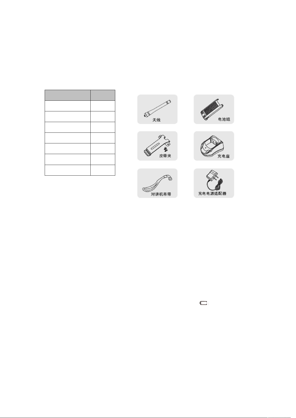
Unpacking and Checking
Unpack the radio carefully. We recommend that you check the radio and the supplied
accessories listed in the following table before discarding the packing material. If any damage or
loss has occurred during shipment, please contact the dealer without delay.
Accessories
Item Quantity
Antenna 1
Battery pack 1
Belt clip 1
Charger base 1
Power adapter 1
Hand strap 1
Instruction manual
1
Preparation
Charging the Battery
The radio is not charged before leaving the factory. Before initial use, please charge the new
battery. Initially charging the battery pack after purchase or extended storage (greater than two
months) will not bring the battery pack to its normal operation capacity, after repeating the
charge/recharge cycle two or three times, the operation capacity will increase to normal. If the
operating time of the battery does not increase after the charging, please change a new battery,
because its life is over.
Type of Charger
Please charge the battery with the charger provided by Kirisun: Charging with unauthorized
charger may cause explosion and personal injury. If the screen displays after the battery is
installed, it indicates that the battery is out of power, please charge the battery.
Attentions
Do not reverse the battery polarity or discard the battery in the fire. Never disassemble the
battery or the cover of the charger. Kirisun does not take the responsibility of any problems
which are caused by any unauthorized modification.
The ambient temperature of charging should be kept within 5~40℃. Charging beyond this
temperature range will affect the performance of the charging and the battery cannot be charged
fully.
Page 5
If you are inserting the radio in the charger to charge, please turn off the radio first, otherwise
it will affect the charging.
During the charging, do not plug off or in the power supply and the battery, otherwise it will
affect the charging program.
If the battery finishes charging, do not reinsert the battery to recharge it, otherwise it will
shorten the battery life and damage the battery.
If the battery or the radio is wet, do not charge the battery immediately. Please wipe off the
liquid first so as to avoid danger.
Warning!
Contacting the conducted metal such as ornament, keys or jewelries with the battery terminal
may cause damage, personal injury. Reversing the terminals will cause large quantity of heat.
When carrying or using the battery, please put it in the insulated container, and never put it in
the metal container.
Steps of Charging
Insert the adapter to the socket of AC output, and then connect the adapter with the charger.
LED indicator lights in orange for one second and then lights off, the charger enters into standby
state.
Insert the battery or the radio into the charger base. Make sure the battery and the charger
terminal is well connected. Then LED indicator flashes in red, and the charger enters into
pre-charge state.
After about 5 minutes, LED indicator stops to flash, and the charging begins.
The battery should be charged for 4 hours. When LED indicator turns to be green, the
charging finishes. And take off the battery or the radio.
Note:
If the radio is inserted into the charger in the power-on state, the LED indicator cannot turn to
be green when the charging is complete. Only when you power off the radio, the indicator will
return to normal. (This is because the radio will consume the battery in the power-on state so
that the battery cannot be charged fully.)
Charging Process
Status
Wait for charging (Self check after inserting in,
orange LED indicator lights for one second.)
Pre-charging (Pre-charging phase)
Start charging (Constant current charging phase)
Finish charging (Constant voltage charging phase)
LED Indicator State
State LED
Self Test Orange (one second)
Indicator state
No display
Red LED indicator lights for 5
minutes.
Red LED indicator lights for 5
minutes.
Greeen Led indicator lights.
Page 6

No battery No display
Pre-charge Red LED indicator lights for 5 minutes.
Charging Red LED indicator lights for 5 minutes.
Complete charge Greeen Led indicator lights.
Error Red LED indicator flashes constantly.
Note: Error includes heat emitting from the radio, short circuit of battery or charger base.
Charging Notice
Self test: When the charger base electrifies, orange LED indicator lights for one second. If the
radio enters pre-charging state, self test passes; if the orange or red LED indicator flashes
constantly, self test fails, and charging cannot be done.
Pre-charge: Insert the battery in; red LED indicator flashes, the battery is in low voltage.
Pre-charge the battery; after the battery voltage arrives to a certain amount (red LED indicator
stops to flash), charge the battery automatically.
Note: T ime for pre-charging cannot exceed 30 minutes. If red LED indicator still flashes after 30
minutes, charging cannot be done. Please check the battery and the charger base.
Battery Storage
Keep the battery in 50% capacity in storage.
Keep the battery in cold and dry environment.
Keep the battery away from the heat source and direct sunlight.
Warning
Do not reverse the battery polarity.
Do not attempt to reassemble the battery cover.
Do not install the battery in the dangerous environment. The sparkle may cause explosion.
Do not discard the battery in the high temperature environment or fire, which may cause
explosion.
Installing/Removing the Battery
Match the three protrusions on the battery pack with the slots at the rear of the radio, and push
forward.
Press the battery down to lock it until a click is heard.
To remove the battery, press down the battery latch, and push backward to separate it from the
radio.
Installing/Removing the Antenna
Installing the antenna:
Hold the base of the antenna, match the antenna with the connector on the top of the radio, and
rotate clockwise until fasten it.
Removing the antenna:
Rotate counterclockwise until the antenna separates from the radio.
Installing/Removing the Belt Clip
Page 7
Installing the belt clip
Match the belt clip with the screw holes at the back of the radio, and fasten it with two screws.
Removing the belt clip
Use screwdriver to take off the screws and remove the belt clip.
Installing the External Earphone
Uncover the cover on the jack; insert the earphone into the jack.
If you do not use the earphone, cover the jack.
Note:
Cover the jack to keep the radio in water resistance state.
Using the earphone will affect the water resistance performance.
Installing the Hand Strap
Cross one end of the hand strap through the ring on the radio; cross the other end through the
strap, and then fasten it.
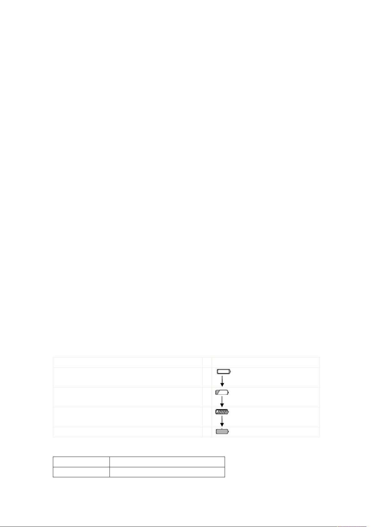
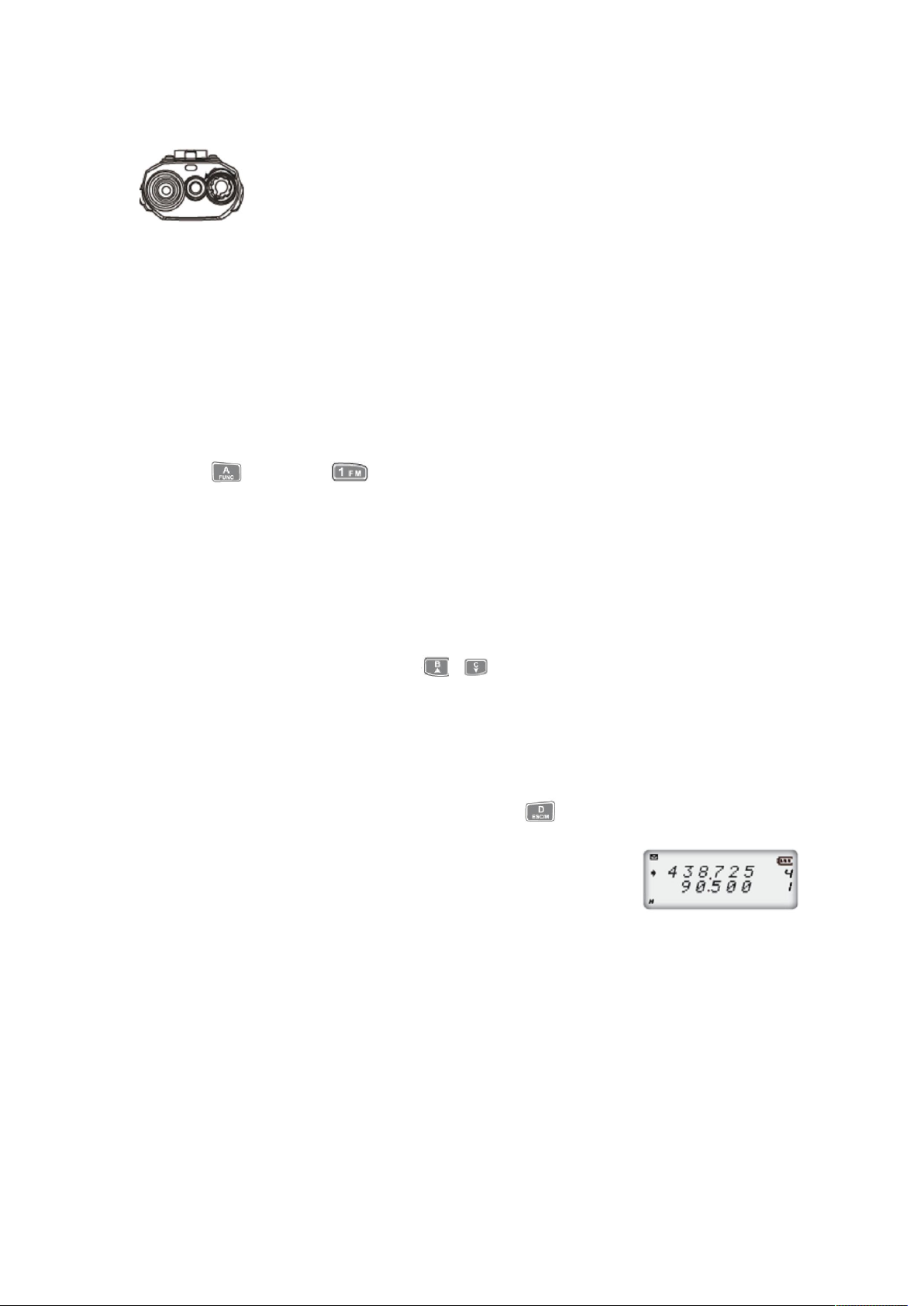
Radio Overview
You can see that there are icons on the screen. The following descriptions help you to know
the meaning of each icon.
Note:
Full voltage
Low battery, Please change or charge the battery.
The remaining battery voltage
Signal strength, voltage
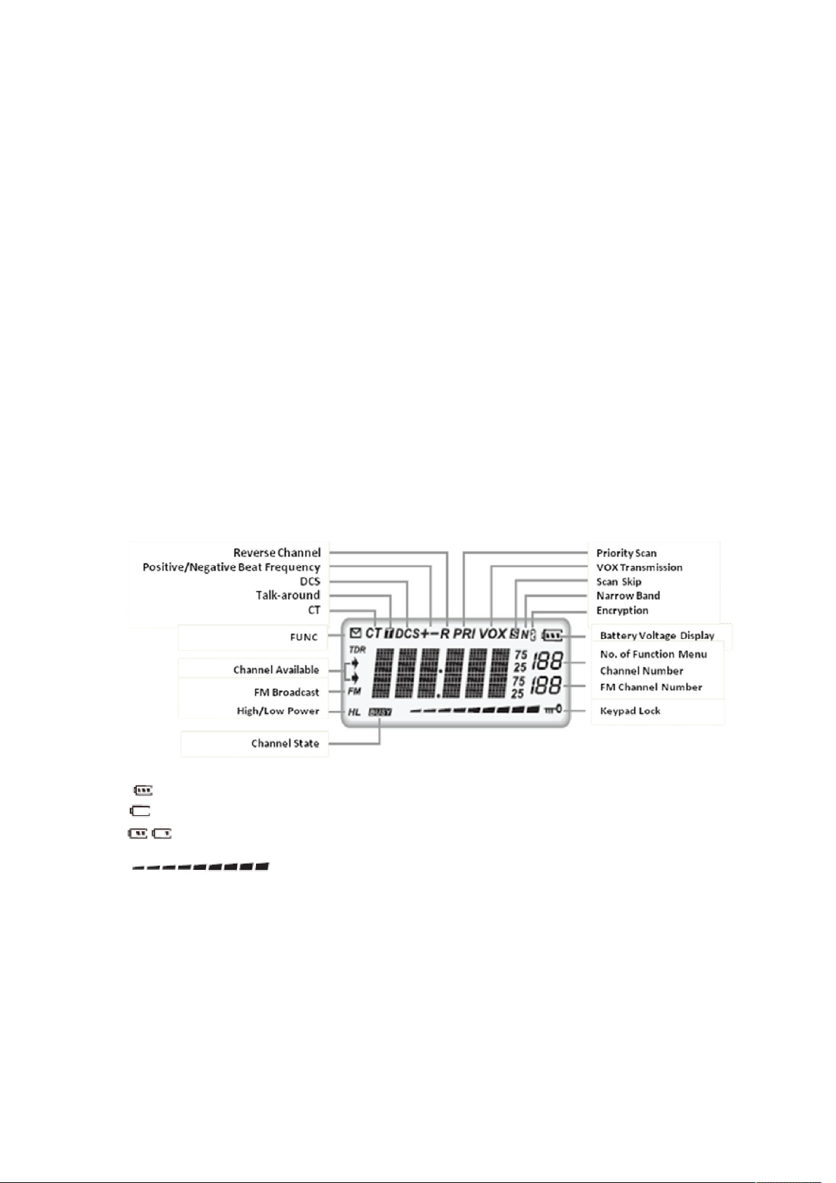
Front View
Page 8
Side View
LED indicator
Microphone
Alarm button
PTT button
Antenna
POWER ON/OFF/VOLUME knob
Speaker
LCD display screen
Keypad
PF1 (programmable button)
PF2 (programmable button)
Powering ON/OFF the radio
Rotate the [POWER]/ [VOLUME] knob clockwise to turn on the radio.
Rotate the [POWER]/ [VOLUME] knob counterclockwise to turn off the radio.
Jack of speaker/microphone/
Programming cable connector
DC connector
Belt clip
Battery
Page 9
Adjust the Volume
Turn on the radio, and rotate the [POWER]/ [VOLUME] knob to adjust the
volume. Rotate clockwise to turn up the volume; rotate counterclockwise to
turn down the volume. During the adjustment, press [PF2] button to monitor
the current background noise. (PF2 can be programmed for different
functions.)
Note: Press the [PF2] programmed as temporary squelch off to monitor the background noise.
Rotate the [POWER]/ [VOLUME] knob to adjust the volume. You can also adjust to the suitable
volume during the communication.
Basic Operation
Switching from Channel Mode to FM Broadcast
Press and then to switch from channel mode to FM broadcast. When
switching to FM broadcast, the radio will turn on FM broadcast and Channel Functions
automatically. The arrows on the display indicate the current available channel.
Note: You can only edit, delete, lock the keypad and On/Off BEEP Tone in FM broadcast, the
rest of the functions are in channel mode.
Searching FM Station
FM broadcast is on, you can press or to search the stations. When a station is
searched, its frequency will display on the screen, and you can listen to this station.
Inputting the Frequency
This function is available in channel frequency mode or FM broadcast frequency mode.
If your radio is in frequency +channel mode, press to switch to temporary channel
mode (VFO).
Note: If the radio is in frequency + channel mode, the current channel
number will display at the right of the screen.
Input the desired frequency with the keypad.
Note: The input frequency should be within the frequency range and conform to step rule. If
this frequency is out of the range or does not conform to the step rule, it is invalid. In the FM
broadcast mode, the step value is 50K.
Inputting the Channel Number
Input 3 digits (e.g. 001~128) of the desired channel number in the frequency + channel mode
or channel name mode, the radio switches to this channel. If this channel is not programmed, the
radio sends out a sound indicating that an error occurs, and returns to the previous channel. 001
refers to channel 1; 030 refers to channel 30; 125 refers to channel 125.
Page 10

Adjusting the Frequency/Channel
In the VFO mode, press / to adjust the current frequency. Press to increase
the frequency; press to decrease it.
Note: Step value available: 5K, 6.25K, 10K, 12.5K, 15K, 20K, 25K, 30K and 50KHz. Please refer
to Step Frequency Settings.
In channel mode, press or to select the desired channel. Press to move to the
next channel; press to back to the previous channel.
Emergency Alarm
Set Side Button [PF1] as Alarm Button. Press it to send out an alarm and transmit the alarm to
the other radio. Press it again to cancel the alarm.
Note: This function must be set by the programming software.
Temporary Squelch/Squelch ON/OFF
Set Side Button [PF2] as Temporary Squelch/Squelch On/Off. Press it to monitor the weak
signal.
Temporary Squelch On/Off: press and hold [PF2] Button, squelch circuit is unmuted; release it
to mute the circuit.
Squelch On/Off: press [PF2] Button, squelch circuit is unmuted; press it again to mute the
circuit.
Note: This function must be set by the programming software.
Receiving a Call
When the working channel is called by the other radio, green LED indicator lights up, and you
can hear the call.
Note: If you have set the squelch to a higher level, you may not be able to receive this call.
If the current channel has set the decoding signaling, the radio can only receive the call from
the radio with the same signaling. (Details please refer to Signaling Relation)
Sending a Call
Press Side button [PF2] programmed as Temporary Squelch/Squelch On/Off to monitor the
signal, and to confirm that the channel you want to transmit is in idle state. Then press [PTT]
button and speak to the microphone.
Please keep your mouth 2.5~5cm to the microphone, and speak in normal tone to transmit
the best voice.
Note: Press [PTT] button, red LED indicator lights up and the call is transmitted; release it to
receive a call.
Side Button [PF1]
Side button [PF1] can be programmed to realize the following functions by short press and
long press:
Page 11

Send a call: in standby state, press [PF1] to send the pre-saved and selected DTMF signaling;
Alarm on: in standby state, press [PF1] to initiate an alarm; the radio will send out an alarm tone
and transmit the alarm to the other radio or the monitor center. Press the button again to end
the alarm. When the alarm sounds for one second, it will automatically turn off and the radio
returns to standby status;
Alarm off: press this button to cancel the alarm when an alarm sounds;
ON/OFF the spotlight: in standby state, press it to turn on the light; press it again to turn off the
spotlight.
To send out the single tone pulse signal (e.g. 1750HZ) in the transmission;
Default setting: short press to turn on the spotlight; long press to initiate the alarm.
Side Button [PF2]
Temporary squelch on/off: in the standby state, press the key to turn on the temporary
squelch; release it to turn off the temporary squelch;
Squelch on/off: in standby state, press this key to turn on the squelch; release it to turn off the
squelch;
Press this key to turn on the radio, and hold it for 3 seconds, the radio enters Radio Function
Settings mode;
Default setting: temporary squelch on/off.
Working Mode Switch (switch from VFO mode to Frequency + Channel Number
mode)
Press to switch from VFO mode to Frequency + Channel Number mode.
Note: If the current channel is not programmed, the operation is invalid.
Shortcut Operation
Editing a Channel
In the VFO mode, input the desired channel frequency, and then press , the icon
displays on the screen. Then press for 2S, a sound of “Du Du” is heard, the screen displays
the signal strength, and you can edit the channel.
Press / to select the desire channel number;
Press and hold for 2S, a sound of “Du Du” is heard, which indicates that the channel is
saved.
Deleting a Channel
In the Channel mode, press , the icon displays at the
Page 12

upper left of the screen. Then press for 2S, a sound of “Du Du” is heard, the radio skips to
the next channel and the previous channel is deleted.
On/OFF FM Broadcast
In the standby state, press , the icon displays on the
upper left of the screen. Then press , the icon “FM” displays on
the screen, which indicates that FM broadcast is on. Repeat the
above operation to turn off the FM broadcast.
ON/OFF Alert Tone
This function is used to alert the input operation, error and malfunction. In the standby state,
press , the icon displays on the upper left of the screen. Then press to turn off
BEEP alert tone. Repeat the above operation to turn on the alert tone. We recommend you to
turn on alert tone.
CTCSS/DCS Scan
Press , the icon displays at the upper left of the screen.
Then press to begin CTCSS/DCS scan. You can press /
to change the direction of the scan. When the CTCSS/DCS matches with
the radio, the scan stops for 15s and then continues. You can press any
keys except , and to exit the scan.
Note: This function is invalid in other mode or the current channel does not set CTCSS/DCS.
If the current channel has set the signaling as CTCSS, the radio scans the CTCSS; if the signaling is
DCS, the radio scans the DCS.
Press / to change the direction of CTCSS/DCS scan.
Setting the Beat Frequency
Press , the icon displays on the upper left of the screen. Then press to
select the direction of the beat frequency. The direction of the beat frequency refers to:
Positive beat frequency
The transmitting frequency is higher than the receiving frequency.
When reverse channel is enabled, the receiving frequency is higher
than the transmitting frequency.
Negative beat frequency
Page 13

The transmitting frequency is lower than the receiving frequency. When the reverse channel
is enabled, the receiving frequency is lower than the transmitting frequency.
No beat frequency
In the VFO mode, frequency + channel mode or channel name mode, press , the icon
displays at the upper left of the screen. Then press to select positive, negative or off
(please refers to Beat Frequency Settings).
Note: This function is invalid in PT280 Professional Radio mode.
Frequency /Channel Scan
In the corresponding mode, press , the icon displays at the upper left of the screen.
Then press to begin frequency or channel scan.
Frequency scan
The scan is available in the VFO mode. This function is used to monitor the signals of each
frequency. Press or digit keys to exit.
Channel scan
In channel mode, this function is used to monitor the signals of each channel. Press or
digit keys to exit.
Note:
Frequency scan will scan all the frequencies. The scan conforms to the preset step rule.
Channel scan will scan all the channels except the skip channel. The direction of the scan is
from small channel number to large channel number. (See Scan Skip)
The direction of Frequency/channel scan can be changed by pressing / . When the
carrier and signaling to be scanned matches with the radio, the radio stays at this
frequency/channel for 15s, and then continues. (See Scan Settings)
Channel Scan Skip
In channel name mode or frequency + channel mode, press ,
the icon displays at the upper left of the screen. Then press
to set the current channel as Channel Scan Skip. Repeat the
above operation to cancel the settings.
When the screen displays “s”, the current channel will not be scanned;
When the screen does not display “s”, the current channel will be scanned.
Page 14

Note: In professional radio mode or frequency mode (VFO), this operation is invalid.
Priority Scan
In channel mode, press , the icon displays at the upper
left of the screen. Then press to enter the priority scan. After
scanning 10 channels, the radio returns to scan the priority channel. When the signal is received
from the priority channel, the radio stays at the channel until the signal disappears. (See Scan
Settings)
Note: This function can only be used when preset by the programming software, or otherwise the
radio just performs the traditional scan. When the radio is in the temporary channel (VFO), this
function is invalid. (See Priority Scan Settings)
High/Low Power
Press , the icon displays at the upper left of the
screen. Then press to select high/intermediate/low
power.
When “H” displays at the down left of the screen, it means
high power transmission.
When “H” or “L” does not display at the screen, it means
intermediate transmission.
When “L” displays, it means low power transmission.
DTMF Encode Check and Settings
Press , the icon displays at the upper left of the screen. Then press to
display the DTMF data of the current group (16 in total).
Press / to select the desired group to check the DTMF data. If DTMF data are not
programmed in the group, the screen displays the current group
number and “_ _ _ _ _ _”.
If the screen displays “_ _ _ _ _ _”, press , the icon
displays at the upper left of the screen. Then press for 2s, a sound of “Du Du” is heard.
You can edit the DTMF data with the keypad now.
After that, press side button [PF2] to dial the DTMF number and save the data.
Sending DTMF Signal Manually
Method 1: press and hold [PTT] button, and then input the desired keys with the keypad.
Page 15

Method 2: press and hold [PTT] button, input the first digit, and then release the button. The
radio will stay at the transmission state for 2S, input other digits within 2S but do not need to
hold [PTT] button. During the transmission of DTMF audio, you can monitor the transmitting
audio by hearing the voice coming from the speaker.
Sending Selected Call, Group Call and All Call with DTMF Encode
This radio can assign different ID to each channel, which can be programmed by the
programming software or manually.
ANI: When the radio receives the matched ANI call, the screen displays the caller’s ID. And you
can identify which radio is sending the call by this ID.
PTT ID: When the working channel is set the PTT ID, this ID will be sent out either by pressing or
releasing the PTT button.
You can assign the different group call codes to different groups (using DTMF characters A, B, C, D,
“*” or “#”). The caller calls different groups by sending out different group codes. The receiver
receives the matched ID from the caller to realize all call, group call or selected call.
For example:
Group code is “C”. And there are four radios, A, B, C, and D.
Their ID codes are 123, 223, 235 and 355.
If the caller has input 123, 223, 235 or 355 when pressing the PTT button, radio A, B, C or D can
receive the call respectively.
If the caller has input “C23” while pressing the PTT button, radio A and B receive the call.
If the caller has input “CC5” while pressing the PTT button, radio C and D receive the call.
If the caller has input “CCC” while pressing the PTT button, all the radios receive the call.
Kill/Waken
By sending out the particular code (code to kill the radio), one
radio can kill the other radio, i.e. disable all the key operations
and functions. When the radio is killed, the screen displays “KILL”.
By sending out the kill code + “#”, one radio can waken the other
radio. E.g. Kill code is “2267”. Thus, send “2267#” to waken the
radio, and the screen displays “WAKEN” when enabled.
Note: Kill code must be edited by the programming software, and cannot exceed 16 digits.
Stun/Waken
By sending out the particular code (code to stun the radio), one
radio can stun the other radio, i.e. temporarily disable all the key
operations and functions except receive the call. When the radio is
stunned, the screen displays “STUN”.
By sending out the stun code + “#”, one radio can waken the other
radio. E.g. Stun code is “2268”. Thus, send “2268#” to waken the
radio, and the screen displays “WAKEN” when enabled.
Note: Stun code must be edited by the programming software, and cannot exceed 16 digits.
When the radio wakens, all the operation and functions enable.
Page 16

Reverse Channel/Talk around
Press , the icon displays at the upper left of the screen. Then press for one
second, Reverse channel or Talk around enables. Repeat the operation above to disable the
function.
Note: When Reverse channel is enabled, perform the operation to turn on or off the function, or
otherwise it is to turn on or off the talk around function.
When “R” appears on the screen, it indicates that reverse channel function is enabled on the
current channel. In this state, the transmitting frequency and
receiving frequency is reversed. If there is CTCSS/DCS signaling, it
will be reversed too.
When “T” appears on the screen, it indicates that talk around
function is enabled on the current channel. In this state, the radio
transmits with the receiving frequency. If there is CTCSS/DCS
signaling, the transmit signal will be encoded by the CTCSS/DCS
decode.
Keypad Lock
In order to avoid of misoperation, you can lock the keypad. In the
standby state, press , the icon displays at the upper left of
the screen. Then press for 2S to lock the keypad. Repeat the operation above to unlock
the keypad.
Note: When keypad is locked, all the keys are useless except [PTT] / [PF1]/ [PF2]/ [A].
Operation and Introduction of Channel Functions
Operations of channel functions temporarily change the function of the current channel. Cut
down the power supply or change the channel function, the settings will not be saved.
In the frequency + channel/channel name or frequency mode, the basic operation is as follows:
* Press , the icon displays at the upper left of the screen. Then press to enter
Function Menu;
* Press / to select the desired function item;
* Press to set this function;
* Press / to select the desired settings;
* Press to return to the previous menu, and press to confirm and exit it.
Note: When the radio is in professional radio mode, operation of pressing and is
Page 17

invalid. In VFO mode, power off or change frequency, the above settings will not be saved.
CTCSS/DCS Decode
When this function is enabled, you can ignore the call from the irrelevant radios which use
the same frequency with you.
Press , the icon displays at the upper left of the screen. Then press to enter
Function Menu;
Press / to select No. 1 Function, the screen displays “R-CDC”;
Press to set this function;
Press to select CTCSS, DCS or OFF. If selecting DCS, you can press
to select DCS normal/inverse code;
Press / to select the desired decoding signaling CTCSS/DCS;
CTCSS: 67Hz-254.1Hz, 50 groups. Default setting is 67Hz;
DCS: 017N-765I, 232 groups. N is the normal code; I is the inverse code. Default setting is 017N.
CTCSS/DCS Encode
Press , the icon displays at the upper left of the screen. Then press to enter
Function Menu;
Press / to select No. 2 Function, the screen displays
“T-CDC”;
Press to set this function;
Press to select CTCSS, DCS or OFF. If selecting DCS, you can
press to select DCS normal/inverse code;
Press / to select the desired encoding signaling
CTCSS/DCS;
CTCSS: 67Hz-254.1Hz, 50 groups. Default setting is 67Hz;
DCS: 017N-765I, 232 groups. N is the normal code; I is the inverse code. Default setting is 017N.
CTCSS/DCS Decode and Encode Synchronization
When this function is enabled, you can synchronize CTCSS/DCS decode and encode.
Press , the icon displays at the upper left of the screen. Then press to enter
Page 18

Function Menu;
Press / to select No. 3 Function, the screen displays
“C-CDC”;
Press to set this function;
Press to select CTCSS, DCS or OFF. If selecting DCS, you can
press to select DCS normal/inverse code;
Press to select the desired encoding signaling CTCSS/DCS;
CTCSS: 67Hz-254.1Hz, 50 groups. Default setting is 67Hz;
DCS: 017N-765I, 232 groups. N is the normal code; I is the inverse code. Default setting is 017N.
Beat Frequency
This function is used to apply the repeater in the communication, i.e. the repeater receives
the signal with one frequency, and transmits the signal with another frequency; the margin
between these two frequencies is the beat frequency.
Press , the icon displays at the upper left of the screen.
Press to enter Function Menu;
Press / to select No. 4 Function, the screen displays “OFFSET”;
Press to set this function;
Press / to select the desired beat frequency;
Frequency range is 00-70MHz. Default setting is 5MHz.
Wide/Narrow Band
You can set the radio to work as wide or narrow band referring to the requirements of
different countries.
Press , the icon displays at the upper left of the screen.
Press to enter Function Menu;
Press / to select No. 5 Function, the screen displays “W/N”;
Press to set this function;
Press / to select the desired settings;
Page 19

Options: 25K (wide band), 20K (intermediate band), 12.5K (narrow band). Default setting is 25K.
Reverse Frequency or Talk around
Press and the icon displays at the upper left of the screen. Then press to
enter Function Menu;
Press / to select No. 6 Function, the screen displays
“REV/TA”;
Press to set this function;
Press / to select the desired settings;
REV: refer to reverse frequency. TA: refer to talk around.
Note: If the current channel is set one of the functions, you can enable the function by pressing
and then in the standby state.
Voice Encryption (prevent from illegal listening)
This function is a special treatment to the voice, which is used to encrypt the communication
so that the radios working with the same frequency cannot hear the communication but only
noises.
Press and the icon displays at the upper left of the screen. Then press to
enter Function Menu;
Press / to select No. 7 Function, the screen displays
“SCREM”;
Press to set this function;
Press / to select the desired settings;
ON: voice encryption is enabled; OFF: voice encryption is disabled. Default setting is OFF.
When this function is enabled, the communication can only continue when the other party also
enables voice encryption function.
Voice Companding (decrease the noise and improve the communication
clearance)
The two communication parties all enable the voice companding function, so that the noise
will be decreased.
Note: The two communication parties must all enable this function so as to use it.
Press and the icon displays at the upper left of the screen. Then press to
enter Function Menu;
Page 20

Press / to select No. 8 Function, the screen displays
“COMP”;
Press to set this function;
Press / to select the desired settings;
ON: voice companding is enabled; OFF: voice companding is disabled. Default setting is OFF.
Busy Channel Lockout
Enabled, the radio cannot transmit on the busy channel. This can avoid of interfering the
other radio which uses the same working frequency as you. When the current channel is busy
and you press the [PTT] button, the radio will send out an alarm. And then the radio returns to
receive signal.
Press and the icon displays at the upper left of the screen. Then press to
enter Function Menu;
Press / to select No. 9 Function, the screen displays “BUSY”;
Press to set this function;
Press / to select the desired settings;
BCL: Carrier busy lockout. The radio prohibits transmitting when receiving the matched carrier on
the current channel.
BTL: Signaling busy lockout. The radio prohibits transmitting when receiving the matched carrier
but different CTCSS/DCS on the current channel.
OFF: disable the function. Default setting is OFF.
Enable/Disable Optional Signaling
The function of the optional signaling is similar to CTCSS/DCS. Besides, selected signaling can also
realize ANI, PTT ID, all call, group call, selected call, stun, kill, waken and etc.
Press and the icon displays at the upper left of the screen. Then press to enter
Function Menu;
Press / to select No. 10 Function, the screen displays
“OPTSIG”;
Press to set this function;
Press / to select the desired settings;
ON: enable this function; OFF: disable this function. Default setting is OFF.
Note: The optional signaling of this radio is DTMF signaling.
Page 21

Signaling Relation
You can set the way of receiving and transmitting in this function.
Press and the icon displays at the upper left of the screen. Then press to
enter Function Menu;
Press / to select No. 11 Function, the screen displays “SIGNAL”;
Press to set this function;
Press / to select the desired settings;
OR: The call can be heard when the radio receives the matched CTCSS/DCS
or the optional signaling.
AND: The call can be heard only when the radio receives the matched CTCSS/DCS and the
optional signaling.
Default setting is OR.
Note: The optional signaling of this radio is DTMF signaling.
PTT ID
Press and the icon displays at the upper left of the screen.
Then press to enter Function Menu;
Press / to select No. 12 Function, the screen displays
“PTT-ID”;
Press to set this function;
Press / to select the desired settings;
OFF: disable the function
BOT: begin, and press [PTT] to send out a string of DTMF encode.
EOT: end, and release [PTT] to send out a string of DTMF encode.
BOTH: from beginning to end, a string of DTMF encode are send out by pressing and releasing
[PTT] button.
Default setting is OFF.
Tx Prohibit
Enabled, the radio cannot transmit but only receive signal on the current channel.
Press and the icon displays at the upper left of the screen. Then press to enter
Function Menu;
Press / to select No. 13 Function, the screen displays “TX-IHB”;
Page 22

Press to set this function;
Press / to select the desired settings;
ON: enable the function; OFF: disable the function. Default setting is OFF.
Whisper
Enabled, you can whisper with the microphone, and the other party can hear a louder voice.
Press and the icon displays at the upper left of the screen. Then press to enter
Function Menu;
Press / to select No. 14 Function, the screen displays
“WHISPE”;
Press to set this function;
Press / to select the desired settings;
ON: enable the function; OFF: disable the function. Default setting is OFF.
Operation and Introduction of Radio Functions
The settings of the radio functions can be adjusted and saved in any mode. The basic
operation is as follows:
Press [PF2] to turn on the radio, and then hold this key for 3S to enter Radio Function Menu;
Press / to select the desired submenu;
Press to enter this submenu;
Press / to select the desired setting;
Press or to confirm and exit.
Voice Annunciation
Enabled, the radio will annunciate the input digits or the state the radio is in when you input
the frequency or channel number with the keypad.
There are two options to be chosen: Chinese annunciation and English annunciation.
Press [PF2] to turn on the radio, and then hold this key for 3S to enter
Radio Function Menu;
Press / to select No.1 Function and the screen displays
“VOICE”;
Page 23

Press to enter this function;
Press / to select the desired setting;
OFF: disable this function; CHN: Chinese annunciation; ENG: English annunciation. Default setting
is CHN.
Timeout Timer
This function is used to prevent the radio from continuously transmitting so as to cause the
overheating of the rear side of the radio. When the time of the radio transmits exceeds the preset
time, the radio will be stopped to transmit forcibly, and an alarm is heard.
Press [PF2] to turn on the radio, and then hold this key for 3S to enter Radio Function Menu;
Press / to select No.2 Function and the screen displays “TOT”;
Press to enter this function;
Press / to select the desired setting;
Options: 15~240S, 4 minutes in total. The interval between each level is
15S.
OFF: disable this function. Default setting is OFF.
VOX
Enabled, the radio can transmit the signal by VOX but not by pressing [PTT] button. You must
first connect the suitable earphone to the radio before applying this function.
Press [PF2] to turn on the radio, and then hold this key for 3S to enter Radio Function Menu;
Press / to select No.3 Function and the screen displays “VOX”;
Press to enter this function;
Press / to select the desired setting;
Options: Level 1~3. The higher the level, the louder the voice is needed.
OFF: disable this function. Default setting is OFF.
VOX Hold Time
In VOX state, if the radio returns instantly to the receiving mode after sending out a call, the
end of the call would not be able to be correctly transmitted due to such a short time. To avoid
this, you can preset a VOX hold time to prolong the transmitting time.
Press [PF2] to turn on the radio, and then hold this key for 3S to enter Radio Function Menu;
Press / to select No.4 Function and the screen displays
“VOXDEY”;
Page 24

Press to enter this function;
Press / to select the desired setting;
Options: 0.5S~5S, 10 levels in total. The interval between each level is 0.5S.
Default setting is 2S.
VOX Alert Tone
Enabled, an alert tone is heard when using VOX to transmit.
Press [PF2] to turn on the radio, and then hold this key for 3s to enter Radio Function Menu;
Press / to select No.5 Function and the screen displays “VOXTON”;
Press to enter this function;
Press / to select the desired setting;
OFF: disable this function; ON: enable the function.
Default setting is OFF.
Step Frequency
In the frequency mode, the input frequency or frequency scan will be limited by the step
frequency.
Press [PF2] to turn on the radio, and then hold this key for 3S to enter Radio Function Menu;
Press / to select No.6 Function and the screen displays “STEP”;
Press to enter this function;
Press / to select the desired setting;
Options: 5K, 6.25K, 10K, 12.5K, 15K, 20K, 25K, 30K, 50K.
Default setting is 5K.
Note: This submenu will disappear in the channel mode.
Squelch Level
This function is used to set the signal strength. When the signal strength arrives to the certain
level, you can hear the other party, or otherwise the radio keeps mute.
Press [PF2] to turn on the radio, and then hold this key for 3S to enter Radio Function Menu;
Press / to select No.7 Function and the screen displays “SQL”;
Press to enter this function;
Press / to select the desired setting;
Options: 10 levels. “0” is the lowest level (means always ON).
Page 25

Default setting is 04.
Battery Save
This radio has battery save function, which helps to prolong the working time. When the radio
receives carrier or the keys are pressed, the radio exits this mode immediately and return back to
the normal state.
Press [PF2] to turn on the radio, and then hold this key for 3S to enter Radio Function Menu;
Press / to select No.8 Function and the screen displays “SAVE”;
Press to enter this function;
Press / to select the desired setting;
OFF: disable this function
1:1 the ratio between normal working state and battery save working state is 1:1
1:2 the ratio between normal working state and battery save working state is 1:2
1:4 the ratio between normal working state and battery save working state is 1:4
Default setting is 1:2
Note: The higher the ratio, the lower power consumption in the standby state is. But it may cause
that the radio misses the small part of the signal sent by the other party at the beginning.
Backlight
The backlight can be set as Always ON, Always OFF and Auto.
Press [PF2] to turn on the radio, and then hold this key for 3S to enter Radio Function Menu;
Press / to select No.9 Function and the screen displays “LIGHT”;
Press to enter this function;
Press / to select the desired setting;
AUTO: automatically on. The backlight turns on automatically and turns off
after a short while automatically.
ON: always on; OFF: always off.
Default setting is AUTO.
Color of Backlight
There are three colors to be chosen.
Press [PF2] to turn on the radio, and then hold this key for 3S to enter
Radio Function Menu;
Press / to select No.10 Function and the screen displays
“COLOR”;
Press to enter this function;
Page 26

Press / to select the desired setting;
ORG: orange backlight
BLUE: blue backlight
PUR: purple backlight
Default setting is PUR.
Scan Temporary Stay Time
This function has three options.
Press [PF2] to turn on the radio, and then hold this key for 3S to enter Radio Function Menu;
Press / to select No.11 Function and the screen displays
“SCANTM”;
Press to enter this function;
Press / to select the desired setting;
5ST: When receiving the matched signal, the radio stays at this channel for 5s and then continues
scanning.
10ST: When receiving the matched signal, the radio stays at this channel for 10s and then
continues scanning.
15ST: When receiving the matched signal, the radio stays at this channel for 15s and then
continues scanning.
Default setting is 15ST.
Display Mode
There are Channel No. mode, Channel frequency + channel No. mode and Channel name +
Channel No. mode to be chosen.
Press [PF2] to turn on the radio, and then hold this key for 3S to enter Radio Function Menu;
Press / to select No.12 Function and the screen displays “DSP”;
Press to enter this function;
Press / to select the desired setting;
FREQ: display channel frequency + channel No. (Non-professional radio
mode, press the specific key to switch to VFO mode)
CH: display channel number (Professional radio mode. Note: If the radio is programmed to
professional radio mode and selected to be locked by the programming software, the radio
cannot return to the non-professional mode by pressing the key manually.)
NAME: display channel name + channel No. (Non-professional mode, press the specific key to
switch to VFO mode)
Default setting is FREQ.
Page 27

Single Tone Pulse Frequency
This function is used to waken the repeater activated by the single tone pulse with certain
volume. If the repeater is ON, single tone pulse is not needed.
There are four frequency options. During transmission, press [PF1] to hear the pulse signal you
have chosen.
Press [PF2] to turn on the radio, and then hold this key for 3S to enter Radio Function Menu;
Press / to select No.13 Function and the screen displays “TBST”;
Press to enter this function;
Press / to select the desired setting;
Four frequency options: 1000Hz, 1450Hz, 1750Hz, 2100Hz.
Default setting is 1750Hz.
DTMF Transmitting Time
Press [PF2] to turn on the radio, and then hold this key for 3S to enter Radio Function Menu;
Press / to select No.14 Function and the screen displays “DTMFSD”;
Press to enter this function;
Press / to select the desired setting;
50MS: every audio signal of DTMF transmits for 50MS and then stops 50MS
100MS: every audio signal of DTMF transmits for 100MS and then stops 100MS
150MS: every audio signal of DTMF transmits for 150MS and then stops 150MS
200MS: every audio signal of DTMF transmits for 200MS and then stops 200MS
250MS: every audio signal of DTMF transmits for 250MS and then stops 250MS
300MS: every audio signal of DTMF transmits for 300MS and then stops 300MS
350MS: every audio signal of DTMF transmits for 350MS and then stops 350MS
400MS: every audio signal of DTMF transmits for 400MS and then stops 400MS
450MS: every audio signal of DTMF transmits for 450MS and then stops 450MS
500MS: every audio signal of DTMF transmits for 500MS and then stops 500MS
Default setting is 100MS.
BEEP Tone Volume
Press [PF2] to turn on the radio, and then hold this key for 3S to enter Radio Function Menu;
Press / to select No.15 Function and the screen displays “VOL-BP”;
Press to enter this function;
Press / to select the desired setting;
Options: 1~5, 5 levels in total.
Page 28

Default setting is level 2.
Priority Channel
During the priority scan, if there is a priority channel, the radio will scan back to this channel
after scanning every 10 channels. When this priority channel appears carrier, the scan stays at
this channel until the carrier disappears.
Press [PF2] to turn on the radio, and then hold this key for 3S to enter Radio Function Menu;
Press / to select No.16 Function and the screen displays “PRI-CH”;
Press to enter this function;
Press / to select the desired setting;
Options: 1~128 channels.
OFF: disable this function
Default setting is OFF.
Note: The priority channel can only be the programmed channel; channels which are skipped in
the scan or unprogrammed cannot be selected.
Battery Voltage Check
Press [PF2] to turn on the radio, and then hold this key for 3S to enter Radio Function Menu;
Press / to select No.17 Function and the screen displays “V-BATT”
and the current battery voltage.
Restore Factory Settings
This function is used to restore the factory settings due to the misoperation of the radio so
that cause the radio unable to use it.
Press [PF2] to turn on the radio, and then hold this key for 3S to enter Radio Function Menu;
Press / to select No.18 Function and the screen displays “RESET”;
Press to enter this function;
Press / to select the desired channel;
FACT? : restore the factory settings (restore the frequency, signaling and functions settings to the
factory settings)
INIT? : restore the radio function settings (the radio function settings (see the above) restores to
factory settings, and the frequency, signaling, channel function settings are unchanged.)
Press to confirm it.
Programming Software Installation
Page 29

(The installation in this manual is set up on WINDOWS XP system.)
1. Double click “QPS280 setup.exe” and install the software step by step.
2. After installation, click the “Start” icon→select “All programs” →find “QPS280” →find and
click “USB to COM Port”. Then install the USB driver step by step.
3. Connect one end of programming cable to PC USB port, another end to the radio.
4. Double click “QPS280”icon on the desktop or click “Start” →“All programs” →“QPS280” →
“QPS280” to start the software. (See figure 1)
5. Select the suitable “COM Port” (See figure 2), click “OK”, then you can start to use it.
Figure 1 Figure 2
Note 1:
On one PC, if the USB programming cable connects to the different USB port, the number of
the COM port will be different.
Please power on the radio before connecting it to PC. Do not turn on or off the radio when
connecting with PC, otherwise the program software cannot be used. Then please close the
software, plug off the programming cable, and then plug in the cable again and start the software.
The software can be used it again. Thus, you’d better connect the radio to the PC after powering
on the radio.
Note 2:
This program software can identify its corresponding radio. Therefore, during the first run of
this software, PT280 must be connected; otherwise this software cannot be used.
Specifications
Frequency range
General specification
VHF: 136-174MHz UHF: 350-390MHz
UHF: 400-480MHz UHF: 450-520MHz
Page 30

No. of channels 128
Channel spacing 25KHz (Broadband), 20KHz (intermediate band), 12.5 (Narrow band)
Step rule 5KHz, 6.25KHz
Voltage 7.4V DC ±20%
Battery
More than 14 hours (1500mAH) (5-5-90)
endurance
Frequency
±2.5ppm
stability
Working
-20-+55℃
temperature
Dimension 195*56*30mm (with battery and antenna)
Weight 185g (with battery and antenna)
Rx part (ETSI EN 300 086 Standard Test)
Broad band Narrow band
Sensitivity (12dB SINAD) ≤0.25μV ≤0.35μV
Adjacent channel selectivity ≥70dB ≥60dB
Intermodulation ≥65dB ≥60dB
Fake signal response ≥70dB ≥70dB
Audio response +1~-3dB (0.3~3KHz) +1~-3dB (0.3~2.55KHz)
SINAD ≥45dB ≥40dB
Audio distortion ≤5%
Audio output power 1000mW/(10%)
Tx part (ETSI EN 300 086 Standard Test)
Broad band Narrow band
Output power 5W/2W/0.5W
Modulation
Adjacent channel selectivity ≥70dB ≥62dB
SINAD ≥40dB ≥36dB
Tx clusters and harmonics ≤-36dB ≤-36dB
Audio response +1~-3dB (0.3~3KHz) +1~-3dB (0.3~2.55KHz)
Audio distortion ≤5%
Page 31

Troubleshooting
Problem Causes and Solutions
The radio cannot be switched
on or no display after being
switched on.
The battery power consumes
quickly after charging.
The radio cannot scan. The channels are not added to the scan list when the radio
Only noise is heard on all
channels after programming.
* The battery power may be insufficient. Please recharge
or replace the battery pack.
* The battery pack may not be installed properly. Please
remove the battery pack and install again.
* The power switch may be broken. Please contact the
authorized local dealer for servicing.
* The battery touch sheet may be broken. Please contact
the authorized local dealer for servicing.
* The battery life is finished. Please replace it with a new
battery pack.
is programmed. (only operated by professional
technicians)
The squelch is ON during the programming. (only operated
by professional technicians)
Cannot hear any voice after
using the earphone for a
period of time.
The communication distance
shortens and the sensitivity
decreases.
Cannot talk to or hear other
group members.
The radio cannot switch on or
always turn off automatically.
The earphone jack is broken. (Please contact the
authorized local dealer for servicing.)
* Make sure the antenna is OK, and the antenna is well
connected with the radio.
* The antenna connector may be broken. The radio may
be in low power state. (Otherwise please contact the
authorized local dealer for servicing.)
* Make sure the frequency/channel is the same as that of
your group members.
* Make sure the CTCSS/DCS/DTMF signal is the same as
that of your group members.
* The radio is out of effective communication range.
The battery touch sheet may be distorted or split.
The receiving voice is small or
intermittent.
Make sure the small hole of MIC is not blocked.
(Otherwise please contact the authorized local dealer for
Page 32

servicing.)
The signal is intermittent and
carries very loud noise.
The voice from the speaker is
smaller after using for a period
of time or there are noises
from the speaker.
The radio can receive the call
but cannot transmit.
The LED indicator lights green
during receiving, but no voice
is heard.
* The communication is out of the range or the signal is
blocked by the high buildings.
* Intermediate filter (450) may be broken. Please contact
the authorized local dealer for servicing.
Make sure that the speaker net is OK, and there is no iron
powder or other things on the speaker diaphragm. (Please
contact the authorized local dealer for servicing.)
Check [PPT] button.
* Check out the volume is loud enough.
* The speaker may be broken. Please contact the
authorized local dealer for servicing.
* The earphone jack may be broken. Please contact the
authorized local dealer for servicing.
* The volume switch may be broken.
Appendix 1 DCS Frequency List
1 017 18 073 35 165 52 261 69 356 86 464 103 632
2 023 19 074 36 172 53 263 70 364 87 465 104 645
3 025 20 114 37 174 54 265 71 365 88 466 105 654
4 026 21 115 38 205 55 266 72 371 89 503 106 662
5 031 22 116 39 212 56 271 73 411 90 506 107 664
6 032 23 122 40 217 57 274 74 412 91 516 108 703
7 036 24 125 41 223 58 305 75 413 92 523 109 712
8 043 25 131 42 225 59 306 76 423 93 526 110 723
9 047 26 132 43 226 60 311 77 425 94 532 111 731
10 050 27 134 44 243 61 315 78 431 95 534 112 732
11 051 28 135 45 244 62 325 79 432 96 546 113 734
12 053 29 143 46 245 63 331 80 445 97 565 114 743
13 054 30 145 47 246 64 332 81 446 98 606 115 754
14 055 31 152 48 251 65 343 82 452 99 612 116 765
15 065 32 155 49 252 66 345 83 454 100 624
16 071 33 156 50 254 67 346 84 455 101 627
17 072 34 162 51 255 68 351 85 462 102 631
Note:
Page 33

1. N refers to normal code, I refers to inverse code. There are 232 groups in total.
2. The digits in bold is non-standard sub-audio frequency.
Appendix 2 CTCSS Frequency List
 Loading...