

Page 1
FM540 Mobile Radio Instruction Manual
II
Page 2

Page 3

FM540 Mobile Radio Instruction Manual
Instruction Manual
FM540
Mobile Radio
We are very grateful for your purchasing KIRISUN brand two-way radios produced
by Kirisun Communications Co., Ltd.
We believe KIRISUN two-way radio, which always incorporates the latest
technology, can bring great convenience to your life and work.
We also believe that the quality and functions of KIRISUN two-way radio can meet your
demands on reliable communication.
II
Page 4

FM540 Mobile Radio Instruction Manual
6.2 Emergency Alarm ...................................................................... 错误!未定义书签。
III
Page 5

FM540 Mobile Radio Instruction Manual
Important Information
◆Copyright
Kirisun and our authorized partners own the intellectual property of all the parts of this product
(include accessories). Any design and materials may not be modified, copied, extracted or
translated without the authorization of Kirisun or its authorized parities.
Due to the update or modification of the product, Kirisun owns the right to change the specifications
of software and hardware described in this manual without further notice. Specifications and
information contained in this manual are for reference only.
◆Safety Notice
The unauthorized operation of wireless transmitting radios is prohibited by local government
regulations. Unauthorized operating will be fined and captured by local government. The
maintenance can only be operated by professional technicians.
Safety: The acknowledge of general dangers is very important for user to operate radio
Warning:
Please turn off the radios when you are in explosive environment (flammable gas, dust and particles
etc.).
II
Page 6

FM540 Mobile Radio Instruction Manual
Notice for User
To avoid fire accidents, personal injury and radio damage, please comply with the following notice:
◆ 1 minute for transmitting and 4 minutes for receiving is recommended. Long period of
transmitting and operating in high power mode will cause high temperature in the bottom of the
radio.
◆ Please do not disassemble and assemble the radio in any situation.
◆ Keep the radio away from long period of sunlight radiation and heating device.
◆ Keep the radio away from dusty, damp and splashy environment. Make sure the radio is not
placed on uneven surface.
◆ The power supply should be cut off once abnormal smell and smoke occur from the radio. And
then please contact the local distributor of KIRISUN.
◆ As the radio is designed to use 13.8V DC, do not connect it to 24V battery.
III
Page 7

FM540 Mobile Radio Instruction Manual
Contents
1 Unpacking and Checking ......................................................................................... 1
2 Preparation .............................................................................................................. 3
2.1 Mobile Radio Installation .......................................................................................... 3
2.2 Attaching the DC Power Cable ................................................................................ 4
2.3 Attaching the Antenna.............................................................................................. 6
2.4 Attaching the Accessories ........................................................................................ 7
3 Product Overview .................................................................................................... 8
3.1 Front Panel .............................................................................................................. 8
3.2 ICON ...................................................................................................................... 10
3.3 Rear Panel ............................................................................................................. 11
3.4 Microphone(Hand-held) ......................................................................................... 12
4 Basic Operation ..................................................................................................... 14
4.1 Switch Power ......................................................................................................... 14
4.2 Adjusting the Volume ............................................................................................. 14
4.3 Selecting a Channel ............................................................................................... 14
4.4 Making a call .......................................................................................................... 14
4.5 Receiving ............................................................................................................... 15
5 Menu Operation ..................................................................................................... 16
5.1 Digital Mode Menu ................................................................................................. 16
5.2 Analog Mode Menu ................................................................................................ 22
6.1 Time Out Timer ...................................................................................................... 23
6.2 Emergency Alarm .................................................................................................. 23
6.3 Voice Encryption .................................................................................................... 25
7 Troubleshooting ..................................................................................................... 26
IV
Page 8
FM540 Mobile Radio Instruction Manual
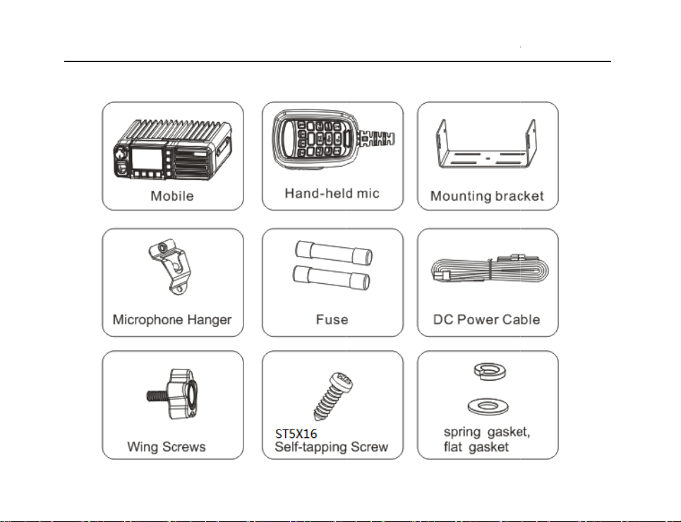
1 Unpacking and Checking
Unpack the mobile carefully. We recommend that you check the mobile and the supplied
accessories listed in the following table before discarding the packing material. If any damage or
loss has occurred during shipment, please contact the delivery man or the dealer without delay.
ITEM QUANTITY
Mobile 1
Microphone (hand-held) 1
Mounting Bracket 1
Micphone Hanger 1
Fuse 5
DC Power Cable 1
Wing Screws 4
Self-tapping Screws (ST5*16) 4
Spring Gasket, Flat Gasket 4+4
Instruction Manual 1
1
Page 9
FM540 Mobile R
a
r
dio
Inst
uction Manual
2
Page 10
FM540 Mobile Radio Instruction Manual
2 Preparation
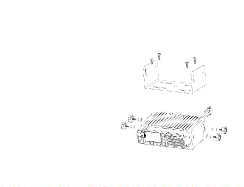
2.1 Mobile Radio Installation
When installing, please choose a safe and convenient
place and try to avoid the danger which may occur
during driving. When selecting the installation location,
please take into consideration that the knee or leg may
hit the mobile during an emergency brake. The best
location choice is a well-ventilated place where
sunshine can’t reach.
1. Use the supplied self-tapping screws to
install the mounting bracket in the car.
2. Insert and tighten the screws and washers
supplied with the mobile. Carefully check and
make sure all screws are tightened to avoid
the loose bracket or loose mobile caused by
the vibrations of vehicles.
3
Page 11
FM540 Mobile R
a
h
V
u
f
b
y
a
e
r
b
d
u
e
s
2
r
y
s
l
r
a
dio
Inst
uction Manual
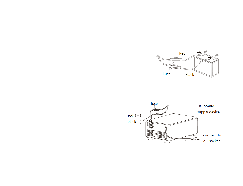
2.2 Attaching t
◆
ehicle Power S
The rated voltage o
not connect the mo
12V vehicle batter
otherwise the displ
output power dropp
1. Confirm the pola
(+), Black: negative
●Use the whole ca
than it is required,
particular, be caref
from the cable.
●It is recommend
lighter socket so a
drop.
e DC Power Cable
pply Connection
the vehicle battery must be 1
ile to a 24V battery. Make su
of sufficient current capacit
y may darken during transmis
d significantly.
ity and connect the power cab
(-).
le, even if the cable is longer
o not cut off the excess. In
l not to remove the fuse box
d not to use the cigarette
to prevent possible voltage
V, and do
e that the
is used,
ion or TX
e to the vehicle battery termin
ls. Red: positive
4
Page 12

FM540 Mobile Radio Instruction Manual
2. Connecting the mobile to the power supply.
● Pressing two connectors until the locking tab clicks .
Note: If you use the mobile for a long time in the case of the vehicle battery is not fully charged, the
engine flameout may consume battery power net, and the remainder of the charge is insufficient to
start the vehicle. So please avoid using mobile in the above case.
◆Connecting the Mobile to the Power Supply
The machine can be installed as a mobile radio or as a base station.
To install the mobile as a base station, the voltage regulated DC power supply of 13.8V voltage and
15A current is required.
1.Connect the DC power cable to the voltage regulated DC power supply, and check if the polarity is
correct (red: positive, Black: negative).
● Do not directly connect the mobile to an AC socket.
● Use the supplied DC power cable to connect the mobile to the voltage regulated DC power supply.
● Do not use a smaller gauge electric wire to replace the cable.
2.Connect the mobile radio DC power connector to the DC power cable connector. Press two joints
until the lock click is heard.
● Before connecting the DC power supply with the mobile radio, turn off the power of the mobile and
the DC power supply
5
Page 13

FM540 Mobile Radio Instruction Manual
● Please connect all the wires before connecting the DC power supply to an AC socket.
◆Replacing the fuse
If the fuse is broken, first identify the cause, and then
solve the problem. Replace the fuse after the problem is
solved. If the new fuse is continuously broken,
disconnect the power cable and contact your dealer or
service center for help.
● Use only the specified type and rating of fuse ,
otherwise the mobile radio may be damaged.
● fuse rating : 15A/32V.
2.3 Attaching the Antenna
Before the operation, please attach the antenna
with high efficiency which is precisely tuned. The
successful attaching depends on the antenna
type and the correct method of attaching it. If the
antenna is carefully chosen and attached, the
mobile radio can achieve its optimum
performance.
6
Page 14

FM540 Mobile R
a
n
e
t
a
e
h
p
e
d
c
o
a
a
w
h
e
a
k
w
l
r
c
dio
Inst
uction Manual
Please use the a
low-loss coaxial fe
input impedance of
Note: Make sure th
proper antenna or it
stations shall be
reduce the possibil
damage.
2.4 Attaching t
◆External Speaker
Please select the s
connect it to the sp
jack accommodates
◆Microphone (Han
For voice communi
standard 8-pin cryst
connector of the m
until a click is heard.
7
tenna of 50Ω impedance
der of 50Ω impedance to m
he mobile radio.
t the mobile radio is attached
may damage the mobile. All t
quipped with lightning prot
ity of fire, electric shock, an
e Accessories
eaker with impedance of 8Ω
aker jack. The external spea
3.5mm mono (double wire) plu
-held Mic)
ation, please plug the mic
al head to the mic / programm
bile front panel. Press the p
Use screws to fix the hand-he
nd the
tch the
ith the
e base
ctor to
d radio
nd
er
g.
ith
ing
lug
d mic hanger to the proper pla
e.
Page 15

FM540 Mobile Radio Instruction Manual
◆PC Connection
Please use a specialized programming cable to connect the mobile radio to your PC computer
(through speaker/programming connector)
3 Product Overview
3.1 Front Panel
8
Page 16

FM540 Mobile Radio Instruction Manual
① Microphone/Programming Interface
② Volume Control Knob
*Adjusting the volume.
LCD Screen③
*See “LCD display” section for details
④ P1 key (programmable key)
⑤ P2 key (programmable key)
⑥ LED Indicator
*Glows red when transmitting and glows green when receiving carrier wave.
⑦ Speaker
⑧ P3 key (programmable key)
⑨ Power Switch Key
*Long press (at least 1.5 seconds) power switch key to turn on/off the mobile.
⑩ [BACK/CANCEL] Key
⑾ Down Key
⑿ Up Key
⒀ [MENU/OK] Key
9
Page 17

FM540 Mobile Radio Instruction Manual
3.2 ICON
Icon Indication
Signal strength indication. The signal gets stronger with more bars.
Unread message.
Speaker is on
Indicates emergency alarm and it appears when receiving
10
Full inbox
Scanning
High power on the current channel
Middle power on the current channel
Low power on the current channel
Keypad is locked.
emergency alarm.
Private call contact
Group call contact
All call contact
Page 18

FM540 Mobile Radio Instruction Manual
401.12500 Channel frequency
CH 8 Channel number or channel alias
3.3 Rear Panel
① Antenna Connector
② Power Connector
③ External Speaker Connector
11
Transmitting signal
Receiving signal
Call holding
Page 19

FM540 Mobile Radio Instruction Manual
3.4 Microphone(Hand-held)
12
Page 20

FM540 Mobile Radio Instruction Manual
1. [PTT] Key
Press the key to transmit signal and release it to receive.
2. [*] Key
Switch between English upper case and lower case in the edit interface.
3. [#] Key
Switch typewriting in the edit interface
4. Numeric Keypad(1,2,3,~9,0):
10 Keys in total. Enter the dialing number or edit messages/new contacts with pressing these keys.
5. Mic Hole
Press the PTT key and speaker to the mic hole.
6. [BACK/CANCEL] Key
7. [DOWN] Key
Press the key to change the channel downwards.
8. [UP] Key
Press the key to change the channel upwards.
9. [MENU/OK] Key
Press this key during the stand-by status to enter the menu, and press this key to confirm the current
selection in the menu.
13
Page 21

FM540 Mobile Radio Instruction Manual
4 Basic Operation
4.1 Switch Power
During the power-off status, long press the Power Switch Key to turn on the mobile, and the LCD
screen will be enabled with automatic back light on and alert tone ringing.
During the power-off status, long press the Power Switch Key and power off the mobile.
4.2 Adjusting the Volume
Rotate the volume knob clockwise to increase mobile volume or counter-clockwise to decrease the
volume.
4.3 Selecting a Channel
Press [▲]or [▼] key on the radio to select channel, or go to the menu to select a channel you need.
4.4 Making a call
◆Selecting the TX power:
1.Enter “Menu”, and select “Power Select”.
2. Press [OK] key,and enter “Power Select”. You can select high power (H), Middle power (M) and
Low power (L).
14
Page 22

FM540 Mobile Radio Instruction Manual
3. Select high power for long communication distance; select low power for short communication
distance in order to save battery power.
Analog Channel◆
1. Press [PTT] key to transmit signal and speak to the microphone.
2. Press [PTT] key and go back to the RX status.
Digital Channel◆
Use one of the following ways to select a contact and initiate a call,
1. Enter the “Contact” menu to select a contact, then press [PTT] key and speak to the microphone.
2. Enter the “Call Log” and select the contact, then press [PTT] key and speak to the microphone.
3. On the home screen, press [PTT] and speak to the microphone, and the calling number is the
default contact. The contact number can be programmed by dealer.
4.5 Receiving
When the mobile receives the RF signal, LCD will show the signal strength.
When using digital channel, the mobile will output all the individual calls, group calls and all calls’
audio.
When using analog channel, the received signal’s CTCSS/DCS matches with the CTCSS/DCS
setting in the mobile, or mobile does not set any CTCSS/DCS, the mobile will output the audio on the
channel.
15
Page 23

FM540 Mobile Radio Instruction Manual
5 Menu Operation
The menu will be different between analog channel and digital channel. Besides, users can decide
whether some partial menu should be displayed in the menu through programming the CPS
software.
Menu Operation:
1.Press [MENU] key to enter menu item.
2.Press [▲]/ [▼] key in the front panel or [UP]/ [DWN] key in the handheld speaker to select menu
item.
3.Press [OK] key in the front panel or handheld speaker to enter the menu item.
4.Press [BACK] key in the front panel or handheld speaker and go back to the last menu.
6.Repeat 1-5 step to enter different menu operation.
Note:During the menu operation, press [PTT] key to transmit and go back to the home screen.
5.1 Digital Mode Menu
If using digital channel, the following items are available in the main menu,
Main Menu
|---Contact
|---Call log
16
Page 24

FM540 Mobile Radio Instruction Manual
|---Message
|---Zone
|---Scan
|---Power Select
|---Digital Signaling
|---Encryption
|---Setting
Contact◆ :
Press [MENU] key to enter the main menu, and select “Contact”, the sub-menu of which includes:
“Contact List”, “Add Contact”,” Make a Call”.
1.You can press [OK] key to enter “Contact List”, “Add Contact” and “Make a Call”. Contact can be
added through programming by dealer or added manually, but only private contact can be added by
manual operation.
2.Enter the “Contact List” to select a certain contact and operate as follows:
*Press [PTT] key to call the contact (mobile radio).
*Press [OK] key to enter “Contact List” menu, then press [▲]/ [▼] key in the front panel or the [UP]/
[DWN] key in the handheld speaker to select the menu.
Call Log◆
Press [MENU] key to enter the main menu, and select “Call Log”. The sub-menu includes, “Dialed
17
Page 25

FM540 Mobile Radio Instruction Manual
Calls” and “Delete All”. The mobile can record the dialed calls and answered calls. While the call log
is full, and a new call occurs, the earliest record will be covered automatically.
Call Logs
|---1 Dialed Calls
|---2 Delete All
1. Enter “Dialed Calls” to select a call record, and press [PTT] key to transmit and call the contact.
2. Select “Delete All’ to delete all the call records, including dialed calls and received calls.
3.Enter “Dialed Calls” to select a record. Press [OK] key could delete the record.
Short Message◆
In this menu, you can edit, send, receive message and send out a quick message. Press [MENU]
key to select “Short Message”. The sub-menus are as follows:
Short Message
|---1 New Message
|---2 Inbox
|---3 Quick Message
New Message:
* Edit a new message through the keypad on the hand-held microphone.
* Press [BACK] key to re-type.
2.Inbox:
18
Page 26

FM540 Mobile Radio Instruction Manual
If a new message is received, the icon will be displayed. If the inbox is full, the icon will be
displayed, and in this condition, the earliest message will be covered by the new message.
3.Quick Message:
There are some pre-saved quick messages set by the dealer in this menu, and you can select any of
them and send it to any contact in your individual call, group call and all call contacts.
Zone Setting◆
A zone can be composed of several channels. You can select any zone you need in this menu.
Scan◆
Press [MENU] key to enter the main menu and select “Scan”. The sub-menus are as follows:
Scan
|---1 Scan on/off
|---2 Delete Channel
|---3 Scan List
* Scan on/off
The scan feature searches for signals from other channels. You can turn on/off scan through this
menu.
* Scan List
Enter “Scan List” and press [OK] key, and then the channels available for scanning can be
displayed.
19
Page 27

FM540 Mobile Radio Instruction Manual
* Delete Channels:
During scanning, when the mobile stops on an unwanted channel, such as interference channel,
“Nuisance Del” can be selected to delete the unwanted channel, and the scanning continues.
Power◆ select
You can set the power through the Menu. High power setting enables a long distance
communication and it requires stronger power supply. “H” indicates high power, “M” indicates middle
power, and “L” indicates low power. The power level of each channel can be set separately.
Digital Signaling◆
*Kill:
You can send “Kill” command to a certain contact to disable the mobile radio.
*Revive:
You can send “Revive” command to a certain contact to re-enable the mobile radio.
*Radio Check:
You can send “Radio Check” command to check a certain mobile without interference to check
whether the mobile is powered-on or whether it is active on the current channel.
*Call Alert
You can send “Call Alert” command to a certain contact (only private contact) to alert the user to call
back.
*Remote Monitor
20
Page 28

FM540 Mobile Radio Instruction Manual
You can send “Remote Monitor” command to a certain contact (only private contact) and monitor the
mobile.
Encryption◆
You can enable/disable the encryption feature.
Setting◆
The operation parameters can be set according to the habits and requirement of users, which
includes back light, keypad lock, LED indication, language and other information.
Setting
|---1 Back Light
|---2 Keypad Lock
|---3 LED Indication
|---4 Key Tone
|---5 Language
|---6 Mobile Radio Information
* Back Light:
Always on :The back light is on at all time.
Always off:The back light is off at all time.
Delay powered-off: Delay the Powering-off the back light according to the selected time.
* Keypad Lock
21
Page 29

FM540 Mobile Radio Instruction Manual
No lock: The keypad will not be locked at all time.
Delay lock: Delay the lock according to the predefined time.
* LED Indication
On:LED indication is enabled.
Off:No LED indication
* Key Tone
On:Key tone is enabled.
Off:No key tone
* Language
The specified language can be selected.
* Mobile Radio Information
The basic mobile information will be displayed, including mobile radio ID, hardware version,
firmware version, data version and serial number.
5.2 Analog Mode Menu
If the analog channel is used, the available menus are as follows:
Main Menu
|---Zone
|---Scan
22
Page 30

FM540 Mobile Radio Instruction Manual
|---Power
|---Squelch Level
|---Setting
The zone, scan, power and setting is the same with the digital menu.
* Squelch Level
The squelch level of the current channel can be set.
6 Feature and Operation
6.1 Time Out Timer
This feature prevents the user from occupying the channel for a long time. If the TX time exceeds the
predefined time set by the dealer, the mobile will stop transmitting with a sound alert. Please release
PTT key in this condition. For a second transmitting, please press PTT key after a certain period(set
by the dealer). If the dealer programs a pre-alert feature, then there will be an alert when it is near
the time out time to indicate that the transmitting will be interrupted soon.
6.2 Emergency Alarm
During emergency, press the emergency key (pre-programmed programmable key) to call for help.
To disable the emergency alarm, please press the emergency key or restart the mobile.
23
Page 31

FM540 Mobile Radio Instruction Manual
The alarm method is made of two parts as follows:
*Alarm type: Specifies the acousto-optic reaction for emergency alarm.
* Alarm mode:Specifies the TX information sent to other mobiles during the alarm. The parameters
can be set by the dealer to meet your requirement.
Alarm Type◆ :
*None:No alarm feature (by default). The alarm cannot be enabled by pressing the key.
*Only siren:Only siren is available.
*Conventional:The acousto-optic alert is available and the mobile can receive replies from other
mobiles.
*Secret:No alarm acousto-optic alert and the mobile will not receive replies from other mobiles.
*Secret with voice: No acousto-optic reaction and the mobile can receive replies from other mobiles.
Alarm Mode◆ :
*Emergency alarm:After the alarm is enabled, the mobile will send out emergency alarm and exit
the alarm status afterwards.
* Emergency alarm +emergency call:The mobile sends out the emergency alarm and press [PTT]
key to send out emergency call.
* Emergency alarm +Auto background tone sending: The mobile will send out emergency alarm and
then send out auto background tone regularly in the way of emergency call.
24
Page 32

FM540 Mobile Radio Instruction Manual
6.3 Voice Encryption
This mobile has voice encryption feature to ensure the privacy of the communication.
Password Setting◆
1. Select “Voice Encryption” in “Menu Setting” menu of PC programming software.
2. To add encryption key at “Voice Encryption Key List” in “Voice Encryption” of PC programming
software, it is secure with more bits. Several encryption key lists can be set.
3. The encryption lists can be selected to use in different channel through PC programming software.
Write the encryption data into the mobile.
◆ Encryption Switch
1. Select “Encryption” in the menu.
2. After pressing [OK] key to enter the encryption interface, you can enable or disable the feature.
The voice will be encrypted when the feature is enabled or not encrypted when disabled.
25
Page 33

FM540 Mobile Radio Instruction Manual
7 Trouble shooting
The following table shows some FAQ of operations. These problems are caused by improper
operation instead of circuit failure. Before identifying the mobile problems, please check the
following table or contact your local distributor.
Trouble Analysis Solution
After connecting to
13.8V power supply
and when the
power-on button is
pressed, the mobile
cannot be switched on
or no screen display.
After selecting high
brightness, the screen
is still dim.
The power cable is
reversely connected.
One or more fuse of
the power cable
is/are blown off.
Power supply voltage
is too low.
Connect the DC power supply cables
properly: Red is positive polarity(+),black is
negative polarity(-).。
Figure out the reason of the blowout. After
checking and solving the problem, replace a
new fuse of the same rating for the cable.
Power supply voltage is required to be
13.8V DC (from 11.7V to 15.8V),If the input
voltage exceeds this range, adjust the
regulated power supply device and make
sure all the power supply cables are well
connected.
26
Page 34

FM540 Mobile Radio Instruction Manual
Most of the keys of
hand-held microphone
does not work.
No signal sent after
pressing the PTT
button.
27
the keypad of the
hand-held
Unlock the keypad.
microphone is locked
The microphone plug
is not completely
connected to the jack
of the front panel.
Channel parameter
setting is incorrect.
Switch off the mobile and connect the
microphone plug into the jack till a “Click” is
heard.
Re-set the parameters.
Incorrect ID Re-enter the correct user ID
Page 35

FM540 Mobile Radio Instruction Manual
28
Page 36

FM540 Mobile Radio Instruction Manual
29
 Loading...