

Kirchner und Tochter RA 65, FA 65 Installation And Operating Instructions Manual
VA Flow Meters
RA 65 / FA 65
Installation and Operating Instructions
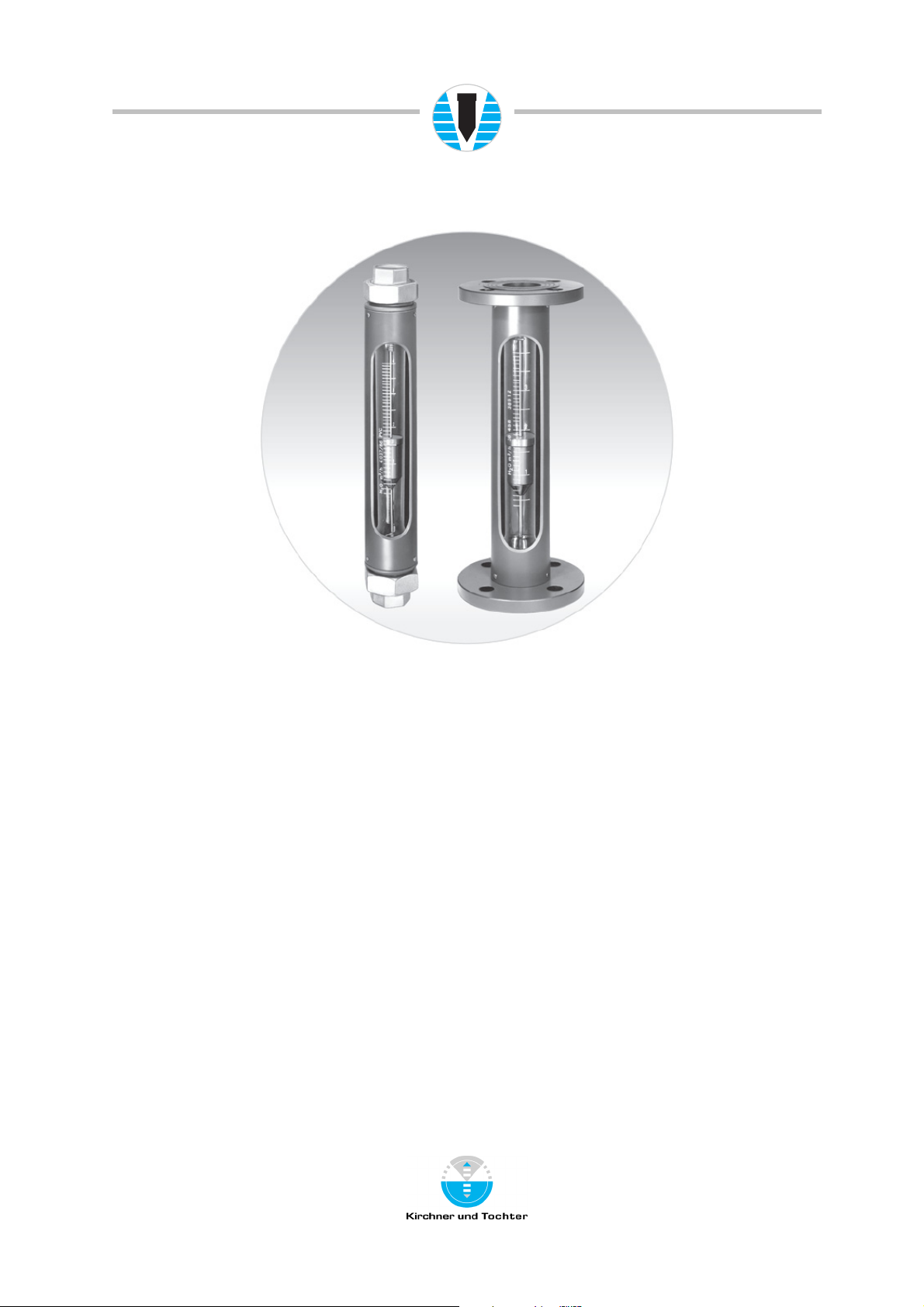
Variable area flow meter
RA 65 / FA 65
A. Kirchner & Tochter GmbH Dieselstraße 17 · D-47228 Duisburg
Fon: +49 2065 9609-0 · Fax: +49 2065 9609-22 Internet: www.kt-web.de · e-mail: info@kt-web.de
Version 1.1

VA Flow Meters
2
RA 65 / FA 65
Contents
1. Foreword.................................................................................................................................................................. 3
2. Safety......................................................................................................................................................................... 3
2.1. Symbol and meaning................................................................................................................................3
2.2. General safety directions and exemption from liability ............................................................ 3
2.3. Intended use ................................................................................................................................................3
2.4. Special safety instructions concerning glass devices.............................................................. 4
2.5. Operator and operating personnel ................................................................................................... 4
2.6. Regulations and guidelines ...................................................................................................................4
2.7. Notice as required by the hazardous materials directive ...................................................... 4
3. Transport and storage......................................................................................................................................4
4. Installation ............................................................................................................................................................... 5
4.1. Installation RA 65...................................................................................................................................... 6
4.2. Installation FA 65 ......................................................................................................................................6
5. Start-up..................................................................................................................................................................... 6
6. Readings in operation........................................................................................................................................ 6
7. Limit contacts MSK-1, MSK-12, MSK-W................................................................................................. 7
7.1. Connection of limit contacts................................................................................................................. 7
7.2. Setting the limit contacts....................................................................................................................... 7
8. Maintenance and cleaning of the flow meter.........................................................................................8
8.1. Dismantling and installation .................................................................................................................8
8.2. Replacement of measuring glass ...................................................................................................... 8
9. Service ...................................................................................................................................................................... 9
9.1. Disposal.......................................................................................................................................................... 9
10. Technical data...............................................................................................................................................10
10.1. Materials ...............................................................................................................................................10
10.2. Dimensions........................................................................................................................................... 11
10.3. Technical data of limit contacts.................................................................................................. 13
10.3.1. Low-Voltage Directive............................................................................................................ 13
A. Kirchner & Tochter GmbH Dieselstraße 17 · D-47228 Duisburg
Fon: +49 2065 9609-0 · Fax: +49 2065 9609-22 Internet: www.kt-web.de · e-mail: info@kt-web.de
Version 1.1

VA Flow Meters
3
RA 65 / FA 65
1. Foreword
These Installation and Operating Instructions are applicable to devices of Series RA 65 and
FA 65. Please follow all instructions and information given for installation, operation,
inspection and maintenance. The Instructions form a component part of the device, and
should be kept in an appropriate place accessible to the personnel in the vicinity of the
location. Where various plant components are operated together, the operating instructions
pertaining to the other devices should also be observed.
2. Safety
2.1. Symbol and meaning
Safety notice
This symbol is placed against all directions/information relating to occupational health and
safety in these Installation and Operating Instructions, and draws attention to danger to life
and limb. Such notices should be strictly observed.
2.2. General safety directions and exemption from liability
This document contains basic instructions for the installation, operation, inspection and
maintenance of the variable-area flow meter. Failure to comply with these instructions can
lead to hazardous situations for Man and Beast and also to damage to property, for which
Kirchner und Tochter disclaims all liability.
The Operator is required to rule out potentially hazardous situations through voltage and
released media energy.
2.3. Intended use
The RA 65/FA 65 Series device is a variable-area flow meter for liquids and gases. It is
designed for installation in vertical pipe runs. Installation in the pipeline should be carried out
solely in accordance with these Instructions. The required version of the variable-area
flowmeter should be selected on the basis of the pipe diameter at the installation location of
the device. The limit values pertaining to the device are specified in Section 10 and must be
complied with. Any modifications or other alterations to the measuring device may be
carried out solely by Kirchner und Tochter. Installation in horizontal pipe runs is possible
using appropriate pipe bends. The direction of flow must always be from bottom to top.
Details of the process product together with the operating conditions are marked on the
measuring glass.
A. Kirchner & Tochter GmbH Dieselstraße 17 · D-47228 Duisburg
Fon: +49 2065 9609-0 · Fax: +49 2065 9609-22 Internet: www.kt-web.de · e-mail: info@kt-web.de
Version 1.1
VA Flow Meters
t
t
4
RA 65 / FA 65
2.4. Special safety instructions concerning glass devices
For safety reasons, we recommend fitting a protective shield in front of the
measuring tube when starting up flow meters fitted with glass measuring tubes.
The devices should not be operated where there is a risk of pressure surges (water
hammer)!
To avoid glass breakage, all fitting work between measuring glass and heads inside the
glass should be carried out by twisting and simultaneously pressing after having wetted the
packing rings/gaskets.
2.5. Operator and operating personnel
Authorized installation, operating, inspection and maintenance personnel should be suitably
qualified for the jobs assigned to them, and should receive appropriate training and
instruction.
2.6. Regulations and guidelines
In addition to the directions given in these Installation and Operating Instructions, observe
he regulations, guidelines and standards, such as DIN EN, and, for specific applications,
he codes of practice issued by DVGW (gas and water) and VdS (underwriters), or the
equivalent national codes, and applicable national accident prevention regulations.
2.7. Notice as required by the hazardous materials directive
In accordance with the law concerning handling of waste (critical waste) and the hazardous
materials directive (general duty to protect), we would point out that all flow meters
returned to Kirchner und Tochter for repair are required to be free from any and all
hazardous substances (alkaline solutions, acids, solvents, etc.).
Make sure that devices are thoroughly rinsed out to neutralize hazardous
substances.
3. Transport and storage
Always use the original packing for transport, handling and storage. Protect the device
against rough handling, impact, jolts, etc.
A. Kirchner & Tochter GmbH Dieselstraße 17 · D-47228 Duisburg
Fon: +49 2065 9609-0 · Fax: +49 2065 9609-22 Internet: www.kt-web.de · e-mail: info@kt-web.de
Version 1.1
VA Flow Meters
5
RA 65 / FA 65
4. Installation
Variable-area flow meters are suitable only for vertical installation, with the direction of flow
being from bottom to top . For all other installation situations, appropriate pipe bends need
to be fitted in the existing pipeline in order to ensure upward vertical flow through the device.
Before installing, remove all protective caps, transport locks and any foreign bodies found.
Make sure the pipes are correctly spaced and in true alignment at the installation location of
the flow meter. For Type RA 65, additionally fit pipe unions to both open ends of the pipeline
before installing the flow meter.
Straight unimpeded pipe runs upstream and downstream of the meter’s installation location
should each have a length equal to 5 x DN (= meter size). Any control equipment, particularly
in the case of gaseous media, should always be located downstream of the flow meter.
The type FA 65 flow meter is sealed off from the pipeline by gaskets. After it has been
installed, the flow meter should not be turned any more. Avoid drawing the ends of the
pipelines together and do not tighten down the device excessively.
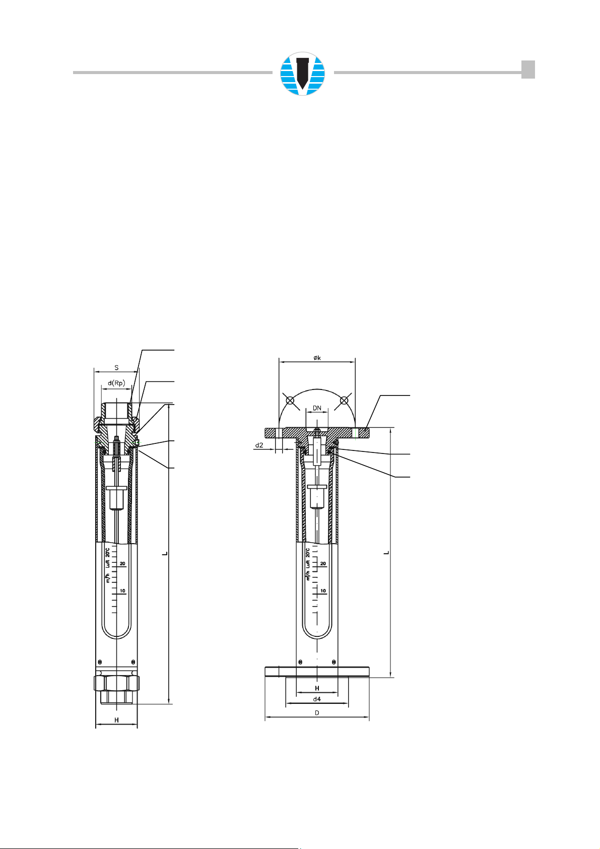
Insert with internal
thread
Union nut
Device head with
external thread
Gasket
O-ring
Device head with
flanged connection
Gasket
O-ring
RA 65 FA 65
A. Kirchner & Tochter GmbH Dieselstraße 17 · D-47228 Duisburg
Fon: +49 2065 9609-0 · Fax: +49 2065 9609-22 Internet: www.kt-web.de · e-mail: info@kt-web.de
Version 1.1
 Loading...