

Kirby Morgan KMB-18 A/B, KMB-28B Operation And Maintenance Manual
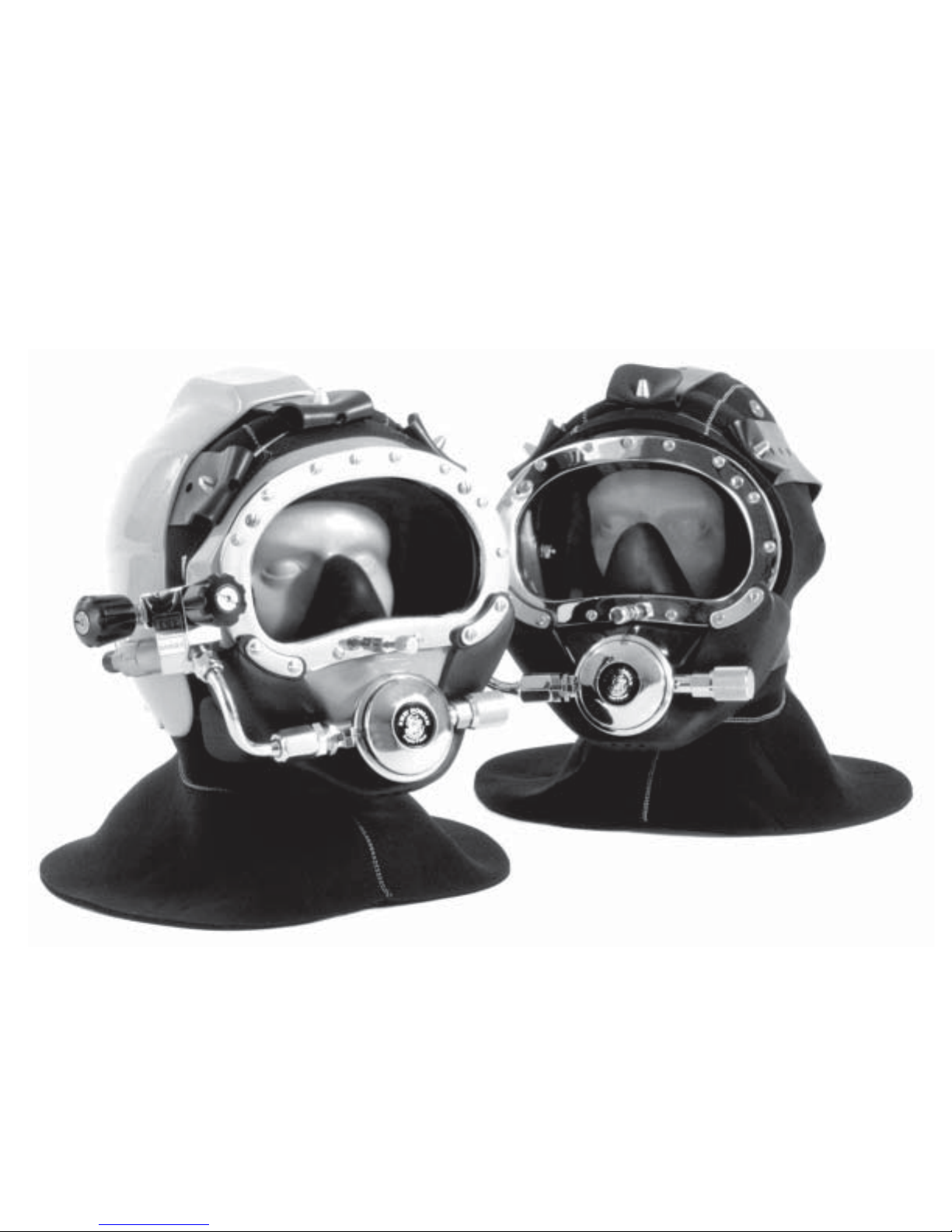
Kirby Morgan Band Mask
KMB-18 A/B and KMB-28B
Operations and Maintenance Manual

KMB 18 & 28 MANUAL
© Copyright 1970-2003 Kirby Morgan Dive Systems, Inc. All rights reserved. Document # 010518001
This page not used at this time.
KMB 18 & 28 MANUAL
Kirby Morgan Band Mask
KMB 18A/B and KMB 28
Operations and Maintenance Manual
KMDSI Part # 100-002
Kirby Morgan Dive Systems, Inc.
425 Garden Street
Santa Barbara, CA 93101, USA
Telephone (805) 965-8538
FAX (805) 966-5761
E-Mail: Info@KMDSI.com
Web Site:www.KMDSI.com
DANGER: Diving with compressed breathing gas is a hazardous activity. Even
if you do everything right there is always the potential for serious injury or death.No one
piece of diving equipment can prevent the possibility that you may be injured or killed
any time you enter the water. We do not herein make any effort to teach the principles
of diving. It is our assumption the reader is a qualified diver.
Manual prepared by Marine Marketing and Consulting & Kirby Morgan Dive Systems, Inc.
SuperLite-17, SuperLite-27, SuperLite-17C, SuperLite-17K, Band Mask, Kirby Morgan, DCS-2A and KMB
are all registered trademarks of Kirby Morgan Dive Systems, Inc. Use of these terms to describe products that
are not manufactured by KMDSI is not permitted.
© Copyright 1970-2003 Kirby Morgan Dive Systems, Inc. All rights reserved. This manual is made available for
the express use of owner of this Kirby Morgan product. No part of this manual may be reproduced, stored in any
retrieval system, or transmitted, or used in any form or by any means, whether graphic, electronic, mechanical,
photocopy , or otherwise by technology known or unknown, without the prior written permission of Kirby Morgan Dive Systems, Inc.
Document # 010518001 © Copyright 1970-2003 Kirby Morgan Dive Systems, Inc. All rights reserved.
Document # 010518001

KMB 18 & 28 MANUAL
© Copyright 1970-2003 Kirby Morgan Dive Systems, Inc. All rights reserved. Document # 010518001
This page not used at this time.

KMB 18 & 28 MANUAL
Contents
DEFINITION OF SIGNAL WORDS .................................................................................................. 1
IMPORTANT SAFETY INFORMATION ........................................................................................... 2
WARRANTY INFORMATION ........................................................................................................... 4
Chapter 1 GENERAL INFORMATION......................................................................................... 7
1.1 INTRODUCTION ....................................................................................................................... 7
1.2 KMB 18A, KMB 18 B and KMB 28 BAND MASK CONFIGURATIONS ............................ 10
1.3 DESIGN PURPOSE ..................................................................................................................10
1.4 CONSTRUCTION SPECIFICATIONS .................................................................................... 11
1.5 GENERAL DESCRIPTION...................................................................................................... 11
1.5.1 Gas Flow Systems .................................................................................................................. 11
1.5.2 Auxiliary Gas Supply System................................................................................................. 13
1.5.3 Reducing Carbon Dioxide ...................................................................................................... 14
1.5.4 Main Exhaust System .............................................................................................................14
1.5.5 Communications..................................................................................................................... 15
1.5.6 Hood and Face Seal ................................................................................................................ 15
1.5.7 Hood and Face Seal Retainer Band ........................................................................................ 15
1.5.8 Head Harness or Spider ..........................................................................................................15
1.6 IMPORTANCE OF PROPER MAINTENANCE ..................................................................... 15
1.6.1 Special T ools........................................................................................................................... 15
Chapter 2 OPERATING INSTRUCTIONS.................................................................................. 17
2.1 INTRODUCTION ..................................................................................................................... 17
2.1.1 First Use of Kirby Morgan 18A/B & 28................................................................................. 17
2.2 PRE DRESS-IN PROCEDURE ................................................................................................ 18
2.2.1 Pre-dive Inspection ................................................................................................................. 18
2.2.2 Clean Face Port....................................................................................................................... 19
2.2.3 Check Moving Parts ............................................................................................................... 19
2.2.4 One Way V alve Check ............................................................................................................ 19
2.2.5 Connecting the Band Mask to the Diver’s Umbilical............................................................. 20
2.2.6 Gas Flow Systems Check ....................................................................................................... 21
2.2.7 Sealing Integrity Check .......................................................................................................... 22
2.2.8 Check Communications.......................................................................................................... 22
Document # 010518001 © Copyright 1970-2003 Kirby Morgan Dive Systems, Inc. All rights reserved.

KMB 18 & 28 MANUAL
2.3 DIVING PROCEDURES .......................................................................................................... 22
2.3.1 Fogging Prevention ................................................................................................................ 22
2.3.2 Bleeding the Umbilical........................................................................................................... 23
2.3.3 Auxiliary Gas System ............................................................................................................. 23
2.3.4 Securing the Band Mask on the Diver.................................................................................... 26
2.3.5 Attaching the Umbilical to the Harness.................................................................................. 27
2.3.6 Diver Check Gas Flow Systems ............................................................................................. 28
2.3.7 Communications Check.......................................................................................................... 28
2.3.8 Diver Ready............................................................................................................................ 28
2.3.9 Water Entry and Descent ........................................................................................................ 28
2.4 EMERGENCY PROCEDURES ............................................................................................... 29
2.4.1 Flooding.................................................................................................................................. 29
2.4.2 Inhalation Resistance.............................................................................................................. 29
2.4.3 Gas Flow Stops....................................................................................................................... 29
2.4.4 Demand Regulator Free Flow................................................................................................. 30
2.5 POST DIVE PROCEDURES .................................................................................................... 30
2.5.1 Removing the Equipment ....................................................................................................... 30
Chapter 3 TROUBLESHOOTING................................................................................................ 31
3.1 GENERAL ................................................................................................................................ 31
3.2 COMMUNICATIONS MALFUNCTIONS .............................................................................. 31
3.3 ONE-WA Y VAL VE MALFUNCTION ..................................................................................... 32
3.4 SIDEBLOCK MALFUNCTION............................................................................................... 32
3.5 DEMAND REGULATOR MALFUNCTION........................................................................... 33
3.6 WATER LEAKAGE INTO BAND MASK............................................................................... 34
3.7 AUXILIAR Y VALVE MALFUNCTION.................................................................................. 34
Chapter 4 INSPECTION/MAINTENANCE TIMETABLE ....................................................... 35
4.1 DAILY MAINTENANCE ......................................................................................................... 35
4.2 MONTHLY MAINTENANCE ................................................................................................. 35
4.3 EVERY SIX MONTHS OR 200 OPERATING HOURS.......................................................... 35
4.4 YEARLY OR EVERY 400 OPERATING HOURS .................................................................. 36
Chapter 5 PREVENTATIVE MAINTENANCE .......................................................................... 37
5.1 INTRODUCTION ..................................................................................................................... 37
© Copyright 1970-2003 Kirby Morgan Dive Systems, Inc. All rights reserved. Document # 010518001

KMB 18 & 28 MANUAL
5.2 REQUIRED TOOLS, CLEANING AGENTS, AND LUBRICATING AGENTS.................... 37
5.2.1 Component and Parts Cleaning ............................................................................................. 38
5.2.2 Component and Parts Lubrication .......................................................................................... 38
5.2.3 Teflon Tape ............................................................................................................................. 38
5.2.4 RTV Sealant............................................................................................................................ 38
5.3 GENERAL ................................................................................................................................ 39
5.4 DAILY MAINTENANCE ......................................................................................................... 39
5.5 MONTHLY MAINTENANCE (OR BETWEEN JOBS).......................................................... 41
5.5.1 Communications Inspection ................................................................................................... 41
5.5.2 Lubricate Nose Block O-Rings............................................................................................... 41
5.5.3 ONE-WA Y VALVE ................................................................................................................ 42
5.5.3.1 Disassembly of the One-Way Valve .................................................................................... 42
5.5.3.2 Reassembly of the One-Way Valve ..................................................................................... 43
5.5.4 DEMAND REGULATOR ...................................................................................................... 44
5.5.4.1 Demand Regulator Test for Correct Adjustment, Fully Assembled .................................... 44
5.5.4.2 Inspection of Regulator Body Interior................................................................................. 45
5.5.5.1 Adjustment System Lubrication .......................................................................................... 45
5.5.5.2 Reassembly of Adjustment System .................................................................................... 47
5.6 DEMAND REGULATOR INTERNAL ADJUSTMENT ......................................................... 48
5.7 HOOD AND FACE SEAL ........................................................................................................ 50
Chapter 6 CORRECTIVE MAINTENANCE .............................................................................. 53
6.1 GENERAL ................................................................................................................................ 53
6.2 PORT RETAINER ..................................................................................................................... 53
6.3 FACE PORT .............................................................................................................................. 53
6.3.1 General.................................................................................................................................... 53
6.3.2 Face Port and Nose Block Device Removal........................................................................... 54
6.3.3 Face Port and Nose Block Replacement................................................................................. 55
6.4 COMMUNICATIONS SYSTEM............................................................................................. 57
6.4.1 General.................................................................................................................................... 57
6.4.2 Earphone Inspection ............................................................................................................... 57
6.4.3 Microphone Removal and Replacement................................................................................. 58
Document # 010518001 © Copyright 1970-2003 Kirby Morgan Dive Systems, Inc. All rights reserved.

KMB 18 & 28 MANUAL
6.4.4 Earphone Removal and Replacement..................................................................................... 59
6.4.5 Waterproof Connector ............................................................................................................59
6.4.5.1 Waterproof Connector Removal .......................................................................................... 59
6.4.5.2 Connector Replacement....................................................................................................... 60
6.4.6 Communications Posts ........................................................................................................... 60
6.4.6.1 Communications Post Removal .......................................................................................... 60
6.4.6.2 Communications Post Replacement .................................................................................... 61
6.5 SIDEBLOCK ASSEMBL Y....................................................................................................... 61
6.5.1 General.................................................................................................................................... 61
6.5.2 Sideblock Assembly Removal ................................................................................................ 62
6.5.2.1 KMB 18A ............................................................................................................................ 62
6.5.2.2 KMB 18B & 28 ................................................................................................................... 62
6.5.2.3 Separating the Sideblock Assembly from the Band Mask Frame ....................................... 63
6.5.3 Sideblock Assembly Replacement.......................................................................................... 64
6.6 DEFOGGER VALVE ................................................................................................................ 66
6.6.1 Disassembly of the Defogger Valve ....................................................................................... 66
6.6.2 Cleaning and Lubricating ....................................................................................................... 67
6.6.3 Reassembly of the Defogger Valve ........................................................................................ 67
6.7 AUXILIARY GAS SUPPLY VALVE ASSEMBLY.................................................................. 68
6.7.1 Disassembly of the Auxiliary Valve Assembly....................................................................... 68
6.7.2 Cleaning and Lubricating ....................................................................................................... 68
6.7.3 Reassembly of Auxiliary Valve .............................................................................................. 69
6.8 MODEL "A" REGULATOR HOSE ASSEMBLY .................................................................... 70
6.8.1 Hose Removal ........................................................................................................................ 70
6.8.2 Inspection, Cleaning, and Lubricating.................................................................................... 70
6.8.3 Hose Replacement .................................................................................................................. 71
6.9 "B" BENT TUBE ASSEMBLY................................................................................................. 72
6.9.1 General.................................................................................................................................... 72
6.9.2 Removal of the Bent Tube Assembly ..................................................................................... 72
6.9.3 Inspection of Bent Tube Assembly ......................................................................................... 72
6.9.4 Replacement of the Bent Tube Assembly............................................................................... 73
6.10 NOSE BLOCK ASSEMBLY................................................................................................... 74
© Copyright 1970-2003 Kirby Morgan Dive Systems, Inc. All rights reserved. Document # 010518001

KMB 18 & 28 MANUAL
6.10.1 Nose Block Assembly Removal ........................................................................................... 74
6.10.2 Nose Block Device Replacement ......................................................................................... 74
6.11 BAND MASK FRAME KMB 18A/B..................................................................................... 74
6.12 RUBBER WHISKER .............................................................................................................. 75
6.12.1 Whisker Removal .................................................................................................................75
6.12.2 Whisker Replacement........................................................................................................... 76
6.13 MAIN EXHAUST ASSEMBLY ............................................................................................. 77
6.13.1 Exhaust Valve Removal........................................................................................................ 77
6.13.2 Main Exhaust Body Replacement ........................................................................................ 77
6.14 DEMAND REGULATOR ASSEMBLY ................................................................................. 78
6.14.1 General.................................................................................................................................. 78
6.14.2 Demand Regulator Assembly Removal................................................................................ 78
6.14.3 Disassembly of the Demand Regulator ................................................................................ 79
6.14.4 Inspection of Demand Regulator Parts................................................................................. 80
6.14.5 Reassembly of the Demand Regulator ................................................................................. 81
6.14.6 Unexplained Demand Regulator Steady Flow When Underwater....................................... 83
6.15 ORAL NASAL MASK............................................................................................................ 84
6.15.1 Oral Nasal Mask Removal.................................................................................................... 84
6.15.2 Inspection of Oral Nasal Mask ............................................................................................. 84
6.15.3 Oral Nasal Mask Replacement ............................................................................................. 84
6.15.4 Oral Nasal Valve Replacement ............................................................................................. 84
Chapter 7 ACCESSORIES ............................................................................................................. 85
7.1 INTRODUCTION ..................................................................................................................... 85
7.2 HOT WATER SHROUD INSTALLATION PROCEDURES ................................................... 85
7.3 LOW PRESSURE INFLATOR HOSE INSTALLATION ON THE “B” SIDEBLOCK ........ 87
7.4 WELD LENS ASSEMBLY INSTALLATION INSTRUCTIONS ........................................... 87
7.5 USE OF QUICK-DISCONNECT ............................................................................................. 88
7.6 MASK CARRYING BAG ........................................................................................................ 88
Appendix I Torque Specifictions ..................................................................................................... 89
Appendix 2 Maintenance Log.......................................................................................................... 90
Table of Equivalents ......................................................................................................................... 91
Document # 010518001 © Copyright 1970-2003 Kirby Morgan Dive Systems, Inc. All rights reserved.

KMB 18 & 28 MANUAL
This page not used at this time
© Copyright 1970-2003 Kirby Morgan Dive Systems, Inc. All rights reserved. Document # 010518001

KMB 18 & 28 MANUAL
Definitions of Signal Words Used in this Manual
For your protection, pay particular attention to items identified by signal words in this manual. These
terms are identified as, CAUTION, WARNING AND DANGER. It is especially important for you to
read and understand these signal words.
CAUTION: This word indicates a potentially hazardous situation which, if not
avoided, may result in minor or moderate injury. It may also be used to alert against
unsafe practices.
WARNING: This word indicates a potentially hazardous situation which, if not
avoided, could result in death or serious injury.
DANGER: This word indicates an imminently hazardous situation, which if not
avoided, will result in death or serious injury.
If English is not your native language and you have any difficulty understanding the language of any
warnings as they appear in the manual, please have them translated.
WARNING: Este é um aviso importante. Queira mandá-lo traduzir.
WARNING: Este es un aviso importante. Sirvase mandario traducir.
WARNING: Quest è un avviso importante. Tradurlo.
WARNING: Ceci est important. Veuillez traduire.
WARNING: Diese Mitteilung ist wichtig. Bitte übersetzen lassen.
If you have any questions regarding the information in this manual, or the operation of your mask,
call Kirby Morgan Dive Systems, Inc. at (805) 965-8538 or E-Mail: Info@KMDSI.com
Document # 010518001 © Copyright 1970-2003 Kirby Morgan Dive Systems, Inc. All rights reserved.
page 1

KMB 18 & 28 MANUAL
IMPORTANT SAFETY INFORMATION
This Kirby Morgan Band Mask (KMB 18 A/B & 28) diving mask is intended for use only by trained
divers who have successfully completed a recognized training course in surface supplied diving.
WARNING: Follow all the instructions in this manual carefully and heed all safety
precautions. Improper use of this diving mask could result in serious injury or death.
DANGER: Kirby Morgan Dive Systems, Inc. (KMDSI) warns all divers who use the
Kirby Morgan Band Mask (KMB 18A/B & 28) to be sure to use only KMDSI original spare
parts from a KMDSI authorized dealer. Although other parts, O-rings and fittings may
appear to fit on the Kirby Morgan Band Mask (KMB 18A/B & 28), they may not to be
manufactured to the same standards maintained by KMDSI. The use of any parts other
than KMDSI original parts may lead to equipment failure and accidents.
DANGER: Diving in an environment that is chemically, biologically, or radiologically contaminated is extremely hazardous. Although the Kirby Morgan Band Mask
(KMB 18A/B & 28) may be adapted for use in some contaminated environments, special
training, equipment, and procedures are necessary. Do not dive in a contaminated
environment unless you have been thoroughly trained and equipped for this type of
diving.
Read this manual before using or maintaining the mask, even if you have experience with other
diving masks. If you have purchased the mask new from a dealer, be sure to send in the warranty
registration card so we may keep you informed regarding any safety notices that affect this
product. If you resell or loan this mask to another diver, be sure this manual accompanies the mask
and that the person reads and understands the manual.
DANGER: Diving is a life threatening occupation. Even if you do everything right
there is still the potential for serious injury or death. Diving a Kirby Morgan band mask
or helmet cannot prevent accidents, injuries, or death.
WARNING: This mask was completely checked and should be ready to dive as it
was shipped from the factory. However, it is always the diver's responsibility to check
all the components of the mask prior to diving.
page 2
© Copyright 1970-2003 Kirby Morgan Dive Systems, Inc. All rights reserved. Document # 010518001

KMB 18 & 28 MANUAL
This manual is supplied to the original purchaser of this mask. If you have any questions about the use,
maintenance, or operation of this mask, or you need another copy of this manual, Part Number 100-002,
contact your nearest KMDSI dealer or Kirby Morgan Dive Systems, Inc. (KMDSI). Telephone:(805)
965-8538, Fax: (805) 966-5761, E-Mail: Info@KMDSI.com
DANGER: Kirby Morgan masks and helmets are not cleaned or lubricated for
oxygen service. Using this mask with oxygen percentages above 50% by volume may
lead to fire or explosions that can result in serious injury or death.
All Kirby Morgan helmets and masks must not be used with oxygen breathing mixtures in excess of 50%
by volume without first insuring all gas transporting components have been cleaned and lubricated for
oxygen service. Only oxygen compatible lubricants such as Krytox® and Christo lube® should be used.
Lubricants must be used sparingly.
The information contained in this manual is intended to aid the user in optimizing the performance of
this helmet. Some of the information will depend on the diving situation and the use of associated
equipment. Many countries have specific laws and rules regarding commercial diving. The operating
and performance specifications listed in this manual on page 8 is separated into two charts. These
charts demonstrate different operation requirements, which are required or imposed by countries or
regulating bodies. It is important for the user to understand the rules, regulations, and philosophy
imposed by the governing regulating bodies whenever using commercial diving equipment. These
charts show the basic operating pressures, depths, and umbilical configurations as required by some
regulating bodies. Whenever Kirby Morgan helmets or masks are used in European Countries, which
have adopted the C.E. certification programs they must only be used with C.E. certified components.
Diving operations should only be conducted within the limits of the operational specifications, and in
accordance with the rules and regulations established by the governing authority in the specific country
or geographical location where the diving operations are being conducted. Please call Kirby Morgan Dive
Systems, Inc. (KMDSI) regarding any operational or performance questions.
Document # 010518001 © Copyright 1970-2003 Kirby Morgan Dive Systems, Inc. All rights reserved.
page 3

KMB 18 & 28 MANUAL
Warranty Information
Kirby Morgan Dive Systems, Inc. (KMDSI) warrants every new mask, helmet, or Dive Control System (DCS) to be free
from defects in workmanship for a period of ninety (90) days from date of purchase. This warranty does not cover rubber
parts or communications components.
Should any part become defective due to materials or workmanship during the warranty period, contact your nearest
authorized KMDSI dealer. If there is no dealer in your area, contact KMDSI directly at (805) 965-8538, E-Mail:
Info@KMDSI.com or Fax (805) 966-5761. You must have a return authorization number (RMA#) from KMDSI prior to
the return of any item. Upon approval from KMDSI, return the defective part, freight prepaid, to KMDSI, 425 Garden
Street, Santa Barbara, CA, 93101. The part will be repaired or replaced at no charge as deemed necessary by KMDSI.
This warranty becomes null and void if:
1. The product is not registered with KMDSI within ten (10) days of purchase.
2. The product has not been properly serviced and maintained according to the appr opriate KMDSI manual.
3. Unauthorized modifications have been made to the product.
4. The product has been abused or subjected to conditions which are unusual or exceed the product's
intended service.
page 4
© Copyright 1970-2003 Kirby Morgan Dive Systems, Inc. All rights reserved. Document # 010518001

This page not used at this time
KMB 18 & 28 MANUAL
Document # 010518001 © Copyright 1970-2003 Kirby Morgan Dive Systems, Inc. All rights reserved.
page 5
KMB 18 & 28 MANUAL
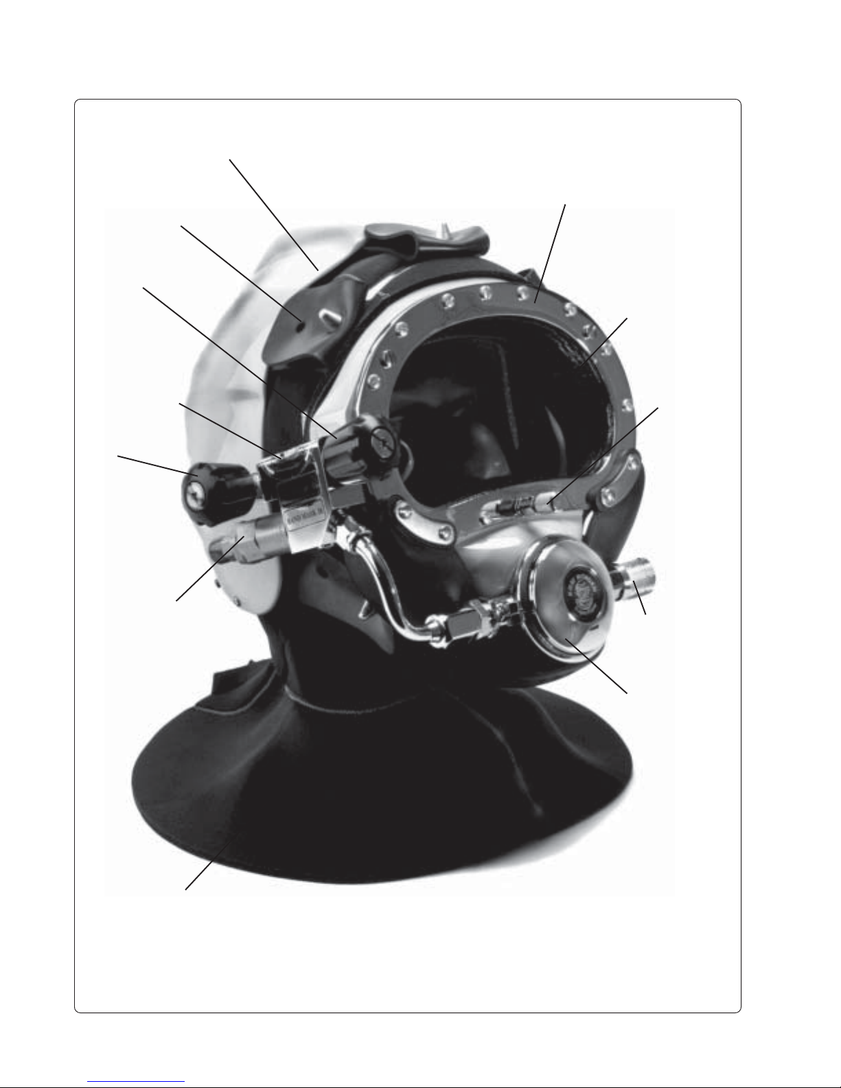
Head protector
Spider
Free flow knob
Sideblock
Auxiliary valve
knob
Port retainer
Port
Equalizing
device
One-way valve
Hood
Regulator
adjustment knob
Regulator
The KMB 18B Band Mask
(shown with optional Hard Shell)
page 6
© Copyright 1970-2003 Kirby Morgan Dive Systems, Inc. All rights reserved. Document # 010518001

STOP!
KMB 18 & 28 MANUAL
BEFORE GOING FURTHER-
Locate the exploded view at the back of this manual. Fold it out and follow the numbers as you read. All
the numbers in parentheses in the text refer to the numbers on the exploded drawing. These numbers are
called “location” numbers on the parts list. They are used to find the referred to parts on the exploded
drawing only. They are not the part number. Always check the part number when ordering to make
sure it is correct. Always specify the mask model number as well. There is only one exploded view
drawing which includes both the Kirby Morgan Band Mask (KMB 18A) and Kirby Morgan Band Mask
(KMB 18B), as well as the Kirby Morgan KMB 28 Band Mask.
CHAPTER 1
GENERAL INFORMATION
1.1 INTRODUCTION
Kirby Morgan Dive Systems, Inc. (KMDSI) started
as the Kirby Morgan Corporation in 1965. Kirby
Morgan is a registered trademark for our products.
William Bev Morgan started designing
and making diving equipment shortly
after becoming a breath-hold diver while
working as a beach lifeguard in the late
1940's. There was very little equipment
available in those early days so it was
necessary to make much of his own gear.
During the early 1950's he originated the Los
Angeles (California) Underwater Instructor
Program for teaching SCUBA divers/instructors, then started Dive 'N Surf, one of the first
diving equipment suppliers that integrated Scuba
diving instruction into the same operation as sales
and service of equipment. He, along with his
partners, Bill and Bob Meistrell, designed and
manufactured diving equipment that remains a
standard in the diving industry today.
In 1957 Morgan sold Dive 'N Surf to his partners.
In 1960 he started commercial diving along with
designing and making diving equipment for the
commercial market.
The Kirby Morgan Corporation was formed to
manufacture commercial diving helmets. The
copper and brass "heavy gear" or " Standard Dress"
helmets were the first manufactured by the com-
Bev Morgan, Chairman of the board,
Kirby Morgan Dive Systems, Inc.
pany. Over the years Kirby Morgan designed,
manufactured, and sold many different helmets
and masks for commercial divers.
Staying active in commercial diving has
contributed to the successful design innovations
of KMDSI products. This may be the primary reason for the acceptance of our designs by professional divers. Over the years,
Morgan has designed more than forty diving
helmets and forty five diving masks.
Document # 010518001 © Copyright 1970-2003 Kirby Morgan Dive Systems, Inc. All rights reserved.
page 7

KMB 18 & 28 MANUAL
All members of the KMDSI staff participate as part of the Kirby Morgan design
team. It would not be possible for us to
supply the commercial, military, scientific,
and public service diving industries with our
equipment without the team of people that
make up Kirby Morgan Dive Systems, Inc.
(KMDSI)
We feel it is important for the reader to
understand that we at KMDSI consider ourselves as only part of the process along the
path in diving equipment design. We welcome all input from our customers. The
thinking of many good divers, diving equipment engineers, diving medical specialists, diving organization administrators and
their supporting personnel has contributed
to the current state of the art of diving.
Each piece of gear we manufacture has in it some
of the thinking of those who have gone before us.
To all the people who give something of themselves to the men and women who work underwater, we express a thank you.
Our extensive dealer network makes it easy to
obtain genuine Kirby Morgan replacement parts
as well as technical assistance world wide. We
have a strong commitment to providing the best
diving equipment and service possible.
Kirby Morgan has always concentrated on designing and manufacturing diving equipment that
allows most repairs and routine maintenance to
be performed by the user. The KMB 18/28 full
face mask is no exception. Most routine preventative and corrective maintenance can be accomplished by the user utilizing this manual, the
KMDSI Tool Kit and common hand tools.
The side block and regulator are of a U.S. Navy
approved design, engineered to provide an optimum flow of breathing gas even under heavy
work conditions.
The mask has been tested and conforms to the
performance requirements as set forth in Annex
II of Directive 89/686/EEC and as far as applicable, the EN250 (edition Jan 2000) and the E
DIN 58 642 (edition Feb 1998). When the mask
is used for air diving in countries that conform to
C.E. regulations it may be used to a maximum
depth of 164fsw (50 msw). I.A.W. EN250.
Only equipment certified and tested according
to EN 250/E DIN 58 642 may be used with the
KMB 18/28 when conducting diving operations
in European EC compliant countries.
Performance of the mask is dependant on many
factors including type of breathing gas used, work
rate, delivery pressure, umbilical internal diameter, length and number of connections, diving
depth and capability of the gas delivery system
to provide breathing media at the required CFM
or LPM to maintain the optimum static over bottom pressure. Performance of this helmet is measured in volume averaged pressure, resistive effort, formally called work of breathing. Volume
averaged pressure is the measurement of average pressures contributed by resistive components within the UBA. This value is normally expressed in Joules/liter. The performance of this
mask can be expected to be less than 3.0 J/L when
used within the following guidelines.
Operational Specifications and Limitations:
- Maximum depth on air - 220 fsw (67 msw) with
the standard exhaust whisker assembly.
- Maximum depth on air - 100 fsw (30 msw) when
equipped with the double exhaust whisker
assembly*.
Work rate - moderately heavy - 62.5 lpm rmv.
-Umbilical minimum I.D. 3/8” (9.5 mm) of one
continuous length (no splice), total length not to
exceed 600 feet (182m).
-Required over-bottom supply pressure,
0-l00 fsw (0-30 msw), 1 15-135 psig (8-9.3 bar).
100-150 fsw (30-50 msw),135-225 psig (9.3-15.5 bar).
100-220 fsw (30-67 msw),175-225 psig (12.0-15.5
bar).
page 8
© Copyright 1970-2003 Kirby Morgan Dive Systems, Inc. All rights reserved. Document # 010518001

-Gas supply system capable of supplying 4.5
acfm (127.4 BL/min) to the side block assembly
at depth.
-T emperature limitations: Use at water temperatures below 36
o
F (2oC) requires use of hot water
shroud and hot water.
The umbilical assembly should be composed of
good quality diving hose that meets industry standards. Generally , gas hose will be married to the
communications wire, pneumofathometer hose,
and strength member in a manner that will allow
the strength member to receive all the strain.
There are also good quality umbilicals available
that are assembled at the factory using a twisted
method which does not require marrying. Regardless of the system used, the umbilical is the divers
life line and should always be of excellent quality and maintained carefully.
* This assembly has not been tested for CE
compliance. Hooded face masks should NOT be
used for diving in contaminated water situations.
The double exhaust is provided for the masks for
use during jetting operations. It has been found
that the use of a double exhaust assembly can
help in the prevention of inversion of the exhaust
valve during heavy jetting operations.
KMB 18 & 28 MANUAL
WARNING: High pressure regulators and associated piping systems for
surface supplied diving with Kirby Morgan helmets and masks must be capable
of delivering a minimum of 4.5 acfm to the
diver at depth. Only systems that can
deliver this required gas flow should be
used. The use of standard SCUBA style
regulators stationed top side is unacceptable as there is no provision for adjusting the intermediate pressure supplied to the diver. This can create a dangerous situation where the diver may not
receive an adequate supply of air. Only
regulators which allow a variable setting
for intermediate pressure should be used
for umbilical diving.
Many of the parts on the Kirby Morgan Band
Mask (KMB 18A/B) are interchangeable with
our SuperLite Helmets, and the Kirby-Morgan
Band Mask 28. This helps keep inventory costs
low for diving companies and independent divers.
The KMB 28 has a durable injection molded
plastic frame (17) rather than a fiberglass frame
as found in the KMB 18A/B.
The diving control station can be at the surface, in
a diving bell, or out of a submerged habitat. The
diving control station is the center of the air/gas
The KMB 28 uses the SuperFlow regulator, the
KMB 18 uses the large tube SuperFlow 350
regulator.
supply, communications with the diver, and diving procedures.
DANGER: Decompression diving
always involves the risk of decompression sickness. Omitted decompression
due to loss of gas supply or other accidents can cause serious injury or death.
Use of a KMB 18/28 mask cannot prevent
this type of injury.
Document # 010518001 © Copyright 1970-2003 Kirby Morgan Dive Systems, Inc. All rights reserved.
page 9

KMB 18 & 28 MANUAL
Additional differences between the Kirby Morgan Band Mask KMB 18A/B and the Kirby
Morgan Band Mask KMB 28 are as follows:
1) The face port (27) in the KMB 28 is a slightly
different size than the KMB 18A/B.
2) The main exhaust body (67) is molded into the
mask frame in the KMB 28.
3) The exhaust covers on the two masks are
slightly different.
4) There is a vacuum formed comfort insert (14)
in the KMB 18A/B.
5) The air train in the KMB 28 requires a special
standoff (24) for proper mounting of the side
block.
It is our hope that the Kirby Morgan Band Mask
(KMB 18A/B or KMB 28), will provide comfort
and safety to your diving. This manual is our
effort to explain the operation, maintenance and
use of the Kirby Morgan Band Mask (KMB 18A/
B & 28).
WARNING: We do not herein make
any effort to teach the principles of diving. It is our assumption the reader is a
qualified diver.
inlet nipple (61b) and jam nut (61c), the two
models are identical. The configuration of the
KMB 28 is almost identical to the KMB 18B.
The Kirby Morgan Band Mask A (KMB 18A)
side block assembly (120a) receives the main and
auxiliary gas supplies from hoses that run down
in front of the diver. The Kirby Morgan Band
Mask 18B (KMB 18B) side block assembly (120b)
receives the hoses from over the diver’s shoulder.
All “location” numbers that are for the “A’ model
will have a small “a” and all “location” numbers
for the “B” only will have a small “b”.
Some divers prefer the hoses to go over their
shoulder to clear their front when working. Others prefer the hoses to go down their front to
prevent fouling. It depends on the type of work
and what the diver finds comfortable.
1.3 DESIGN PURPOSE
The Kirby Morgan Band Masks 18A/B & 28 are
designed for use with an umbilical.
WARNING: Only under very con-
trolled conditions, i.e., non-moving water
(such as swimming pools or calm lakes),
can this mask be used with a self contained gas supply. There is no provision
for surface swimming once the SCUBA
air supply is depleted.
If there is any information in this manual that is
not clear, contact Kirby Morgan Dive Systems,
Inc. at (805) 965-8538 for clarification.
1.2 KIRBY MORGAN BAND MASK A (KMB
18A), KIRBY MORGAN BAND MASK B
(KMB 18B), AND KIRBY MORGAN BAND
MASK 28 (KMB 28) CONFIGURATIONS
The Kirby Morgan Band Mask 18 (KMB 18) is
manufactured in two configurations. With the
exception of the side block assembly (120a/b),
the hose assembly (117a) with its inlet nipple
(61a), and the bent tube assembly (117b) with its
page 10
© Copyright 1970-2003 Kirby Morgan Dive Systems, Inc. All rights reserved. Document # 010518001
The umbilical is usually composed of at least a
gas or air supply hose and communication wire,
assembled with waterproof tape to form a single
unit. Some umbilicals also have included a hose
for hot water, a pneumofathometer hose, and a
strength member, such as a cable or strong line. It
is imperative that air/gas umbilicals be married to
a strength member in a manner that allows the
strength member to receive the strain. This will
help reduce the possibility of umbilical and umbilical fitting fatigue and possible failure. The
umbilical is the diver’s lifeline to the diving
control station.

KMB 18 & 28 MANUAL
The diving control station can be at the surface, in
a diving bell, or out of a submerged habitat. The
diving control station is the center of the air/gas
supply, communications with the diver, and diving procedures.
DANGER: Decompression diving
always involves the risk of decompression sickness. Omitted decompression
due to loss of gas supply or other accidents can cause serious injury or death.
Use of a KMB 18/28 mask cannot prevent
this type of injury.
WARNING: High pressure regulators for surface supplied diving with the
Kirby Morgan Band Mask 18A/B and KMB
28 mask must be capable of supplying an
over bottom pressure of between 115 and
225 PSI. The use of standard SCUBA style
regulators stationed top side is unacceptable as there is no provision for adjusting the intermediate pressure supplied to the diver. This can create a dangerous situation where the diver may not
receive an adequate supply of air. Only
regulators which allow a variable setting
for intermediate pressure should be used
for umbilical diving.
The surface supplied diver’s mask must provide
life support breathing systems, communications
components, viewing lens, and many other less
important, but vital systems. The Kirby Morgan
Band Masks 18A/B and 28 provides these systems in a convenient and comfortable way.
1.4 CONSTRUCTION SPECIFICATIONS
KIRBY MORGAN BAND MASK
KMB 18A/B & 28
Weight: 11 pounds
CONSTRUCTION:
Mask Frame KMB 18A/B, Fiberglass
Mask Frame KMB 28, Xenoy/Polycarbonate mix
HARDWARE:
Stainless Steel, Chromed Brass, Polished Brass
CONTROL KNOBS: ABS Plastic
LENS: Polycarbonate plastic
O-RINGS: Buna-N
HOOD: Foam, Open Cell Neoprene
RECOMMENDED LUBRICANTS:
Dow Corning #55 O-ring silicone lubricant.
Krytox, and Crysto Lube are also acceptable.
OPERATING PRESSURE: 115-225 PSI over
ambient.
Optimum 150 PSI over ambient
FLOW REQUIREMENTS: 3.2 CFM
COMMUNICATIONS:
Earphones - Mylar Cone 8 OHM
Oral Nasal Microphone - 8 OHM
1.5 GENERAL DESCRIPTION
1.5.1 Gas Flow Systems
The main gas supply flow from the umbilical
enters the system at the adapter (105) and flows
through the automatic one-way valve (104) to the
interior of the side block assembly (120a/b). The
one-way valve (104) or “non-return” is a very
important component. It must prevent the flow of
gas out of the mask to the umbilical in the event
of a sudden lowering of pressure in the supply
hose. This can happen due to an accidental break
in the hose or a fitting near the surface. Not only
would the auxiliary gas be lost if the one way
valve failed (concurrent with a hose or fitting
break on deck), but the diver would be “squeezed”,
a very serious accident. Although we have se-
Document # 010518001 © Copyright 1970-2003 Kirby Morgan Dive Systems, Inc. All rights reserved.
page 11
KMB 18 & 28 MANUAL
lected the valve for its reliability and quality,
inspection and maintenance of this valve must be
done regularly. It is very easy to disassemble and
inspect. (A rebuild kit for this valve is available,
KMDSI Part #525-330).
WARNING: The one way valve must
be tested daily, prior to the commencement of diving operations. Failure of the
one way valve could cause serious injury
or death. Follow the procedures for testing the valve in chapter 2 (sec. 2.2.4) of
this manual.
The auxiliary gas comes from a tank of compressed gas worn by the diver. It enters the system
through the auxiliary valve (103) when the diver
turns the control knob (100) on. The flow then
enters the side block, (94a/b).
diver’s warmth and moisture. The flow continues
out through the mask main exhaust (66), or into
the oral nasal (9) by means of the valve (5), then
into the regulator and out through the regulator
exhaust (62). The diver can breathe from this
flow of gas if the demand regulator malfunctions.
Returning to the side block assembly (120a/b):
the other passage for gas is to the regulator (63a/
b). It goes to a hose assembly (117a) on the “A”
model or a bent tube assembly (117b) on the “B”
model. The flow of gas in the demand regulator
assembly (63a/b) is controlled by an automatic
valve that supplies gas to the diver on inhalation
“demand” only, and shuts off during the exhalation cycle.
The SuperFlow demand regulator (63a/b) senses
WARNING: Never connect the main
gas supply hose from the diving station
to the auxiliary valve (103). There is no
one way valve in the auxiliary valve. If this
mistake is made, any break in the supply
hose could possibly result in a “squeeze”.
The KMB 18A/B and KMB 28 use a stud (93) and
a machine screw (25) to mount the side block
assembly (120a/b).
The nut (20), lock washer (19), and flat washer
(18) bed solidly on the interior of the mask frame
(17) wall securing the side block assembly (120a/
b). Both sources of gas flow through the same
passage in the side block body (94a/b) to two
exits. One exit is always open to supply gas to the
demand regulator assembly (63a/b). The other
exit is to the defogger valve (free-flow valve)
assembly (83 through 92).
The diver controls the flow of gas through the
defogger system with the control knob (85). The
flow enters the mask and flows through the air
train (21) which directs the gas onto the face port
(27) to prevent fogging that forms there from the
Inflator hose connects here.
The “B” sideblock allows you to connect a low pressure
hose to your dry suit.
the start of the divers inhalation and opens the
flow valve, matching the diver’s need. The regulator continues to match the diver’s inhalation as
the rate increases, peaks, then ebbs and stops.
When the diver exhales, the supply gas stays off
as the exhalation gas flows through the regulator
body (39), out the regulator exhaust valve (62),
through the whisker (35), and out into the water.
The whisker (35) deflects the exhaust bubbles
away from the face port (27) to keep the diver’s
view clear.
page 12
© Copyright 1970-2003 Kirby Morgan Dive Systems, Inc. All rights reserved. Document # 010518001

All Kirby Morgan Helmets and Bandmasks are
equipped with a multi turn demand regulator
adjustment knob. The purpose of this adjustment
knob is to allow the diver the ability to compensate for variations in umbilical supply pressure.
This adjustment device operates by simply increasing or decreasing the amount of spring bias
tension on the demand regulator inlet valve. The
adjustment knob has a range of approximately 13
turns from full in to full out. The intent of this bias
adjustment device is strictly to allow the diver to
make adjustments for variations in umbilical supply pressure. This adjustment device is not intended as a minimum-maximum device. Minimum and maximum applies to supply pressure
only. The adjustment knob should be adjusted by
the diver to be at the easiest breathing setting at all
times. The exact number of turns required is
dependent on the supply pressure. Diving a
KMDSI helmet or bandmask with a bias setting
greater than that just necessary to keep the demand valve from free flowing increases the work
of breathing and reduces the diver's ability to
perform heavy work.
The adjustment knob (47) allows the diver to
control the regulator for a wide range of incoming
gas pressures. Normally, this would be from 115
P.S.I. to 225 P.S.I. over ambient (diver) pressure.
It is important to have this control at the diver for
the least breathing resistance.
The Kirby Morgan Band Mask 18B and KMB 28
side block is drilled and tapped to accept low
pressure inflator hoses. This allows the diver the
capability to inflate variable volume dry suits or
buoyancy compensators. It is tapped with a 3/8"24 thread orifice, standard for American first
stage scuba regulator low pressure auxiliary fittings. The port is shipped plugged at delivery.
KMB 18 & 28 MANUAL
WARNING: When using the side
block low pressure inflator port. The Operator should only use high quality hoses
with an integrated flow restrictor or a
KMDSI flow restrictor PN# 555-720. All
hoses must have an in-line restrictor to
reduce the gas flow in the event of hose
failure. Do not use fitting adapters, standard adapters do not provide an adequate
flow restriction. The use of many off the
shelf adapters on the side block assembly could expose the low pressure hose
fittings to excessive stress. Any failure of
an inflation hose will subject the diver to
a decreased supply pressure.
1.5.2 Auxiliary Gas Supply System
All divers using Kirby Morgan surface supplied
helmets and masks must always have a diver
worn auxiliary gas cylinder fitted with a first stage
regulator and hose that is connected to the inlet
of the auxiliary supply valve (103). The size of
the cylinder should be such that will allow the
diver to safely ascend to the surface or to a point
where the normal gas supply can be restored. The
first stage regulator should always be fitted with
the KMDSI overpressure relief valve.
WARNING: Be sure the auxiliary
air/gas first stage regulator is fitted with
an overpressure relief valve. A leaky first
stage can overpressure the hose, bursting it and causing a loss of the entire
auxiliary air/gas supply and possible
physical injury to the diver as the hose
whips about. Do not use a high pressure
hose as the system on the helmet is not
designed for high pressure.
Document # 010518001 © Copyright 1970-2003 Kirby Morgan Dive Systems, Inc. All rights reserved.
page 13
KMB 18 & 28 MANUAL
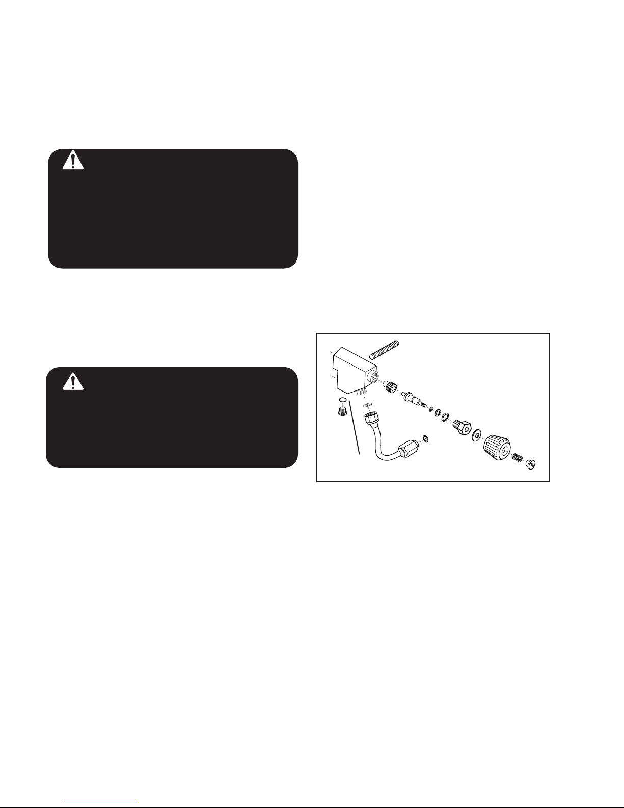
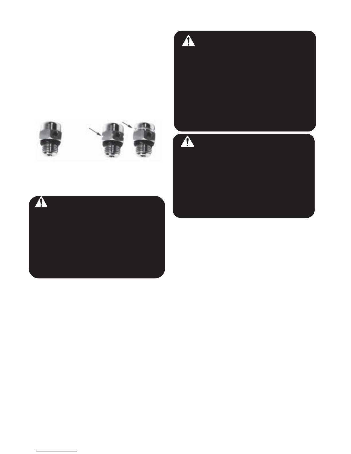
The KMDSI Overpressure relief valve, part
number 200-017, has been manufactured in two
different flow rates. The original valve had a
lower flow rate that the current valve. The current
valve has been marked in two ways, the first
being a groove around the flats of the hex. Currently the valve is marked with a groove around
the top of the body. These are the same valve, just
different marks.
Shown are the three versions of the over pressure relief
valve
DANGER: Your auxiliary air/gas
supply on a deep mixed-gas dive is extremely limited. All divers must be aware
of exactly how long their bailout bottle
will last at depth. For example, a diver
breathing one cubic foot of air a minute at
the surface will use a 50 cubic foot bailout
bottle in approximately 7 minutes at 198
FSW while at rest.
1.5.3 Reducing Carbon Dioxide
It is important to reduce the internal volume of the
mask that the diver is breathing through. Carbon
dioxide (CO2) can build up if proper flushing does
not occur. A rubber oral nasal mask (9) is located
inside the mask to fit over the diver’s nose and
mouth. The oral nasal (9) attaches to the regulator
mount nut (8). This separates the breathing gas
flow from the larger gas space on the interior of
the mask, and this in turn reduces carbon dioxide
buildup.
WARNING: Always be sure the oral/
nasal valve is properly mounted in the
oral nasal mask. If the valve is mounted
improperly or absent this can lead to a
higher CO2 level inside the mask. A higher
CO2 level can cause dizziness, nausea,
headaches, shortness of breath, or blackout. This can also increase the probability
of decompression sickness. The correct
flow of gas is from the mask into the oral
nasal.
DANGER: Do not confuse the oral/
nasal valve with the main exhaust valve.
They are not the same thickness. The
main exhaust valve is much thicker. Using the main exhaust valve in the oral
nasal valve body will restrict the air flow
to the diver. Using the oral nasal valve in
the main exhaust could cause water to
leak into the mask.
1.5.4 Main Exhaust System
The main exhaust system (64,65,66,67) is located
at the bottom of the mask frame (17). Breathing
gas exiting through this valve automatically purges
water from the interior of the mask. This happens
naturally because the valve (66) is the lowest part
of the mask during normal working or swimming
conditions. The cover (65) may be removed by
unscrewing the two screws (64) . Removal of the
cover (65) permits access to the rubber mushroom valve (66). The main exhaust body (67) on
the KMB 18 is held in place by three screws (69).
(Note: The main exhaust body is molded directly
into the mask frame on the KMB 28.)
The rubber mushroom valve (66) is designed to
present a resistance to the flow of exhaust gasses.
This is necessary to prevent the demand regulator
(63a/b) from turning on a steady flow when the
diaphragm (52) is positioned lower than the main
exhaust (66) during a dive. The diver does not
encounter this resistance as he exhausts out of the
regulator exhaust.
page 14
© Copyright 1970-2003 Kirby Morgan Dive Systems, Inc. All rights reserved. Document # 010518001

KMB 18 & 28 MANUAL
1.5.5 Communications
The Kirby Morgan Band Mask (KMB 18A/B and
28) communications system is very simple. For
two wire (push to talk) communications systems,
the left earphone (11) with the longer wire, and
the right earphone (10) with the shorter wire, are
wired in parallel with the microphone (12) to the
communications posts (73). These posts (73) are
also known as “bare wire” connectors. The wire
that is part of the umbilical bundle is connected to
these connectors.
The KMB 18A/B & 28 may also be fitted with a
waterproof connector (80). This system comes
standard with a terminal block (82) that is used
with four wire communications, also known as
“round-robin” systems. The terminal block can
also be wired for two wire systems if preferred.
Electrical signals are sent to, and received from,
the surface through the umbilical wires. An amplifier boosts the signals to the desired volume for
the surface and the diver. The diver is always
“on” in a two wire system, except when the
tender pushes a switch to talk to the diver. In a
four wire system, both top side and the diver can
speak at the same time, just as you would on a
telephone.
1.5.7 Hood and Face Seal Retainer Bands
(15, 16, 68)
The top band (16) and the bottom band (68) fit
around the hood and face seal combination (2)
and clamp it firmly to the mask frame (17). Two
screws (15) hold these bands in place. Five spider
“hooks” consisting of stainless steel posts welded
to the retainer bands (16,68) are located on the top
and bottom bands. The top band (16) has three
stainless steel posts. The bottom band (68) has
two stainless steel posts.
DANGER: The bands must be tightened properly or the mask frame may
separate from the hood and face seal. If
this happens the diver can drown and
death may result.
1.5.8 Head Harness or “Spider”
The five legged head harness or “spider” (1) is a
simple and convenient method of keeping the
mask in place against the diver’s face. The multiple holes punched in each leg allow adjustment
to fit any size head. It will be more comfortable if
the lower rear or neck area is as low as possible on
the diver’s neck. If this lower portion of the spider
(1) is too high, it will cause the face seal to push
up on the chin causing discomfort.
1.5.6 Hood and Face Seal
The hood and face seal (2) is fabricated from
foam neoprene and open cell foam. The open cell
foam forms a comfortable cushion that pushes the
sealing surface of the foam neoprene against the
diver’s face.
1.6 IMPORTANCE OF PROPER
MAINTENANCE
Although the Kirby Morgan Band Mask KMB
18A/B is a rugged piece of equipment, proper
care and maintenance is essential. The demand
breathing system is simple in design but subject
to malfunction if not properly maintained. Nor-
The hood incorporates built-in pockets that are
open to the interior of the mask frame (17). These
pockets retain the earphones (10,11). It is very
mal wear requires periodic internal adjustment to
the regulator. This will assure the diver of easy
breathing.
easy to remove the earphones for maintenance.
1.6.1 Special Tools
If the standard hood does not fit your head comfortably, other sizes are available from your
KMDSI dealer.
A Regulator Adjustment Tool Kit (KMDSI Part
#525-620) containing four special adjustment
tools is available for internal adjustment of the
demand regulator assembly (63a/b). These tools
make regulator adjustment much easier. The tool
kit comes in a convenient, wallet sized pouch
with instructions.
Document # 010518001 © Copyright 1970-2003 Kirby Morgan Dive Systems, Inc. All rights reserved.
page 15
KMB 18 & 28 MANUAL
DANGER: Without correct, regular
maintenance, your mask will not function
properly. A poorly functioning mask can
cause a fatal accident.
WARNING: When purchasing
spare parts, always insist on Kirby Morgan Genuine Parts. Although other parts
may look the same, they may not be
manufactured to the same standards of
quality. Improperly manufactured parts
can cause accidents.
page 16
© Copyright 1970-2003 Kirby Morgan Dive Systems, Inc. All rights reserved. Document # 010518001

CHAPTER 2
OPERATING INSTRUCTIONS
2.1 INTRODUCTION
This section provides the manufacturer’s advice
on how to use the Kirby Morgan 18A/B and 28
Band Masks. The use of these diving Band Masks
will vary with the type of work and environmental conditions.
DANGER: The basic procedures of
donning and removing the Kirby Morgan
18A/B or 28 will be similar for every job. A
proper training program in a calm, clear
body of water must be undertaken. If the
diver has not used the Kirby Morgan 18A/
B or KMB 28 before, he must not go on a
job without proper training. Death could
result due to a lack of familiarity with the
mask.
KMB 18 & 28 MANUAL
Be sure to complete the enclosed warranty card
and return it to KMDSI immediately. No warranty claims will be honored without a satisfactorily completed warranty card on file at KMDSI.
The card enables KMDSI to know what unit you
have so we can contact you in the event of a safety
notice being issued for this product. It is your
responsibility to keep the factory notified of any
change of address you may experience.
CAUTION: It is the responsibility
of the end user to register their ownership
of this mask with Kirby Morgan. If the
mask is not registered KMDSI has no way
to contact you regarding product upgrades.
Divers that are familiar and trained in the use of
WARRANTY INFORMATION
previous mask designs of Kirby and Morgan
(Models 8, 9, 10, the Navy MK. 1, the SuperLite17A/B, or the SuperLite-27) will find the Kirby
Morgan 18A/B and 28 to have the breathing
system controls located in the same position and
the operation of the Band Mask will be similar.
Kirby Morgan Dive Systems, Inc. warrants every
new mask, helmet, or Dive Control System (DCS),
to be free of defects in workmanship for a period
of ninety (90) days from date of purchase. This
warranty covers all metal, fiberglass, and plastic
parts. This warranty does not cover rubber parts,
communications components, or Band Mask
The numbers appearing in parentheses are “loca-
hoods.
tion” numbers on the parts list, which appear on
the “blowapart” illustration at the end of this
manual. You should fold out the blowapart illustration to view while you read this section.
Should any part become defective, contact your
nearest authorized KMDSI dealer for a replacement.
This warranty becomes null and void if:
2.1.1 First Use of Kirby Morgan 18A/B & 28
1) The product is not registered with KMDSI
within ten (10) days of purchase.
When you first receive your Kirby Morgan KMB
18A/B or KMB 28, carefully unpack it and examine it for any damage that may have occurred
during shipment. Use the inspection sheet provided to ensure that no damage has occurred
during shipment. The purchaser must contact the
freight carrier and/or the KMDSI dealer if the
2) The product has not been properly serviced and
maintained according to the appropriate KMDSI
manual.
3) Unauthorized modifications have been made
4) The product has been abused or subjected to
conditions which are outside normal diving conditions or exceed the product’s intended service.
Band Mask has been damaged in shipment.
Document # 010518001 © Copyright 1970-2003 Kirby Morgan Dive Systems, Inc. All rights reserved.
page 17

KMB 18 & 28 MANUAL
2.2 PRE DRESS-IN PROCEDURE
Before dressing in for a dive, inspection of the
Band Mask system must be made to be sure it is
in proper working order. This must be done well
in advance of the dive, so any problems can be
fixed without delaying the dive. The following
steps are part of the recommended daily maintenance which is also in Section 4.1.
DANGER: All parts on the Kirby
Morgan 18A/B must be adjusted to their
proper torque specifications. See Appendix 1 for a complete listing of torque
specifications for each part. Failure to
adjust parts to the recommended specifications could lead to Band Mask failure
and accidents. This could be fatal.
2.2.1 Pre-Dive Inspection
Inspect the exterior and interior of the Band
Mask.
1) The demand regulator cover assembly (51)
must not be dented.
2) Inspect the regulator hose assembly (117a) on
the “A” model, and the bent tube assembly (117b)
on the “B” model. There must be no dents or kinks
in the bent tube assembly. The hose assembly
must be in good shape.
3) Inspect the face port (27). It must be in good
condition.
4) Check the inside of the Band Mask. Be sure the
communications wires are hooked up and there
are no loose nuts. Check the wire lugs to make
sure they are not touching each other. This would
cause a short (no communications).
5) Inspect the oral nasal mask (9). Make sure it is
on the regulator mount nut (8) properly.
6) Check the screws (29) on the port retainer (28).
They must be adjusted to the proper torque setting
(12 inch pounds (13 kg cm)) per the specifications in Appendix 1 of this manual. Binder head
screws are used in this application for their self
locking characteristics. Overtightening will strip
out the threaded inserts in the Band Mask frame
(17).
page 18
© Copyright 1970-2003 Kirby Morgan Dive Systems, Inc. All rights reserved. Document # 010518001
DANGER: Never use RTV to glue
on the port retainer or to hold the threaded
inserts in the mask if they are loose. If the
RTV fails it could cause the mask to flood
and lead to drowning. This can be fatal.
7) Check the spider (1) to ensure there are no tears
or cracks in the material. If the spider is worn or
cracked it must be replaced. All five “legs” of the
spider must be present.
DANGER: The spider must be in
good condition. If it is worn or cracked it
could fail during the dive. This could cause
the mask to flood or come off the diver’s
head. This could lead to drowning.
8) Check the hood and face seal (2). The hood
must be in good condition with no tears or rips.
The face seal must be properly glued to the hood.
If it is not, or there are tears in the face seal this
will cause the regulator to free flow.
CAUTION: A torn face seal will
cause the regulator to free flow. This could
lead to a rapid consumption of the diver’s
air supply if bottled breathing gas is being used.
9) Check the screws (15) that hold the bands (16
& 68) in position. They must be adjusted to the
proper torque setting (see torque specs pg. 89)
When the screw are adjusted properly, the hood
and face seal cannot be moved from under the
bands.
10) Be sure to inspect the bands themselves (16 &
68). The welds must show no signs of cracking or
parting.
DANGER: If the bands become
loose the hood and face seal could separate from the mask. This would cause the
mask to flood which could cause drowning.
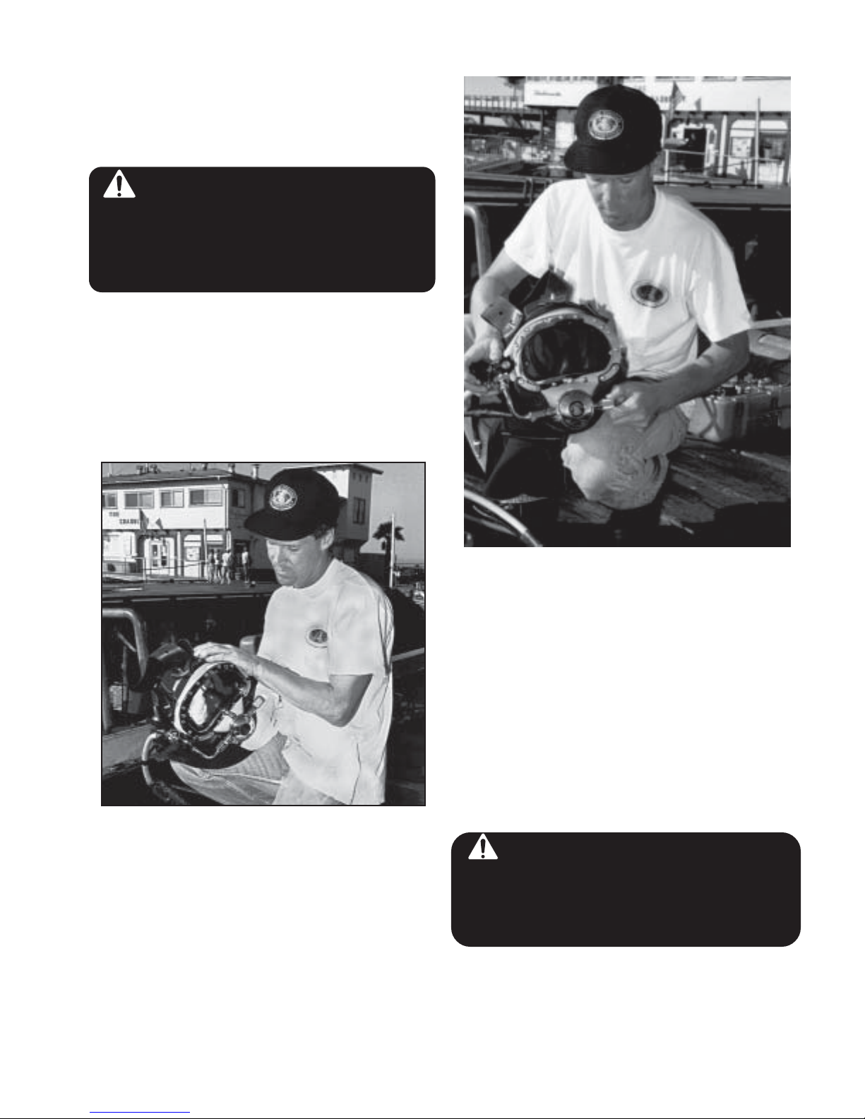
2.2.2 Clean Face Port (27)
Remove any sand or dirt on the interior of the face
port (27) which might cause scratches when antifogging solution is applied prior to the next dive.
KMB 18 & 28 MANUAL
Fig. 2.1 Clean the face port prior to use.
2.2.3 Check Moving Parts
Check all moving parts, such as the regulator
adjustment knob (47), the defogger control knob
(85), auxiliary knob (100), and the nose block
device knob (34) to ensure smooth and proper
operation.
Fig.2.2 Moving parts, such as the regulator adjustment
knob must be checked before the Band Mask is put on
line.
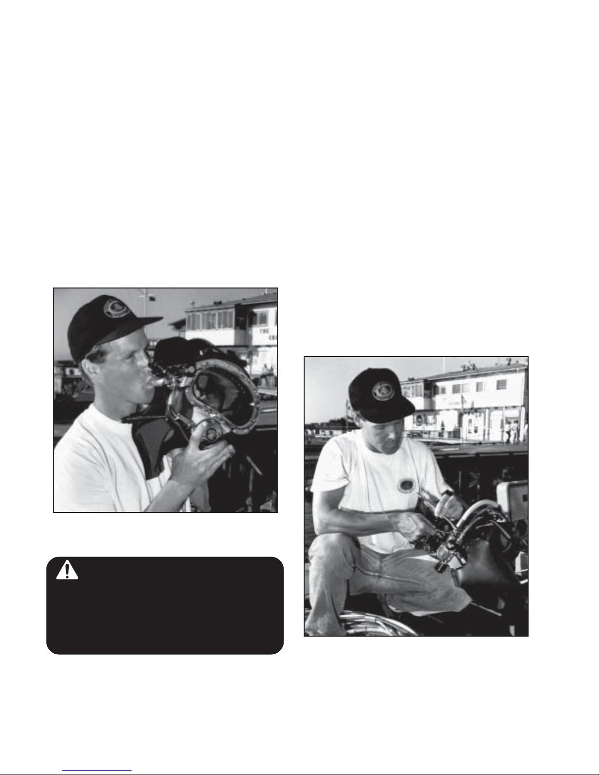
2.2.4 One-Way Valve (104) Check
There are two ways to check the one-way valve
(104). Check both ways if possible.
1) Leaving the auxiliary knob (100) open (on) and
not hooked up to the supply hose, try to suck air
out of the adapter (105). If any air comes out, the
one-way valve must be replaced.
WARNING: The one way valve must
be tested dailly, prior to commencement
of diving operations. Failure of the one
way valve could cause serious injury or
death.
Document # 010518001 © Copyright 1970-2003 Kirby Morgan Dive Systems, Inc. All rights reserved.
page 19
KMB 18 & 28 MANUAL
2) Prior to attaching (or pressuring up) the umbilical, close the auxiliary valve (103), and attach and
pressure up the auxiliary hose. Shut off the defogger control knob (85) and screw in the adjustment
knob (47) on the regulator all the way. With the
auxiliary hose pressurized, turn on the auxiliary
valve knob (100). If any gas escapes out the
adapter (105) or (if attached) into the unpressurized umbilical hose, the one-way valve (104) is
faulty and must be replaced. Flow into the unpressurized umbilical hose can be heard. A
one-way valve repair kit is available for rebuilding these valves (KMDSI Part # 525-330). Contact KMDSI at (805) 865-8538 if you have any
questions regarding rebuilding your one-way
valve.
2.2.5 Connecting the Band Mask to the Diver’s
Umbilical
When you connect the hose to the Band Mask, be
sure to use a wrench to hold the adapter, or inlet
fitting, (105), and a second wrench to turn the
fitting on the hose. If this is not done, the adapter
(105) will turn inside the one-way valve (104). If
this happens repeatedly the threads will wear and
the valve will need to be replaced. The connection between the hose and the Band Mask must
only be made up “snug”. Excessive force will
deform and ruin the adapter (105). A second
wrench must be used when the Band Mask is
disconnected as well, otherwise the adapter (105)
and/or the one-way valve assembly (104) may
become loose and fail to make a seal. If this
happens it is necessary to remove the adapter,
clean off all the thread tape, and reseal it using
Teflon tape.
Fig. 2.3 Always check the one-way valve prior to diving.
WARNING: Never dive if the oneway valve is not operating properly. If the
hose breaks near the surface a serious
injury could result to the diver’s lungs
and/or eyes. In extreme cases this could
be fatal.
page 20
© Copyright 1970-2003 Kirby Morgan Dive Systems, Inc. All rights reserved. Document # 010518001
Fig. 2.4 Always use two wrenches to connect the umbilical
to the KMB 18A/B or 28.
 Loading...