

Kirby Morgan KM 97 Installation Instructions Manual
O
M
R
Y
B
R
I
K
G
A
N
Kirby Morgan Dive Systems, Inc.
1430 Jason Way Santa Maria, California 93455
®
Phone: 805/928-7772 Fax: 805/928-0342
D
I
V
E
S
Y
S
E
T
.
c
n
I
,
S
M
www.KirbyMorgan.com email: kmdsi@KirbyMorgan.com
Part #525-761
KM 97 Water Shroud Kit
Installation Instructions
Part # Description Qty.
510-723 Regulator Shroud, 455 1
510-733 Access Cover 1
510-734 Side Block Shroud 1
510-736 Water Tube A 1
510-737 Water Tube B 1
520-039 Tie Wrap 6
Tools Required:
Part # Description Qty.
520-049 Tie Wrap 4
550-074 Bishop Pin 2
550-572 Adapter Sleeve 1
550-580 Adapter Sleeve, Long 1
550-644 Pin 1
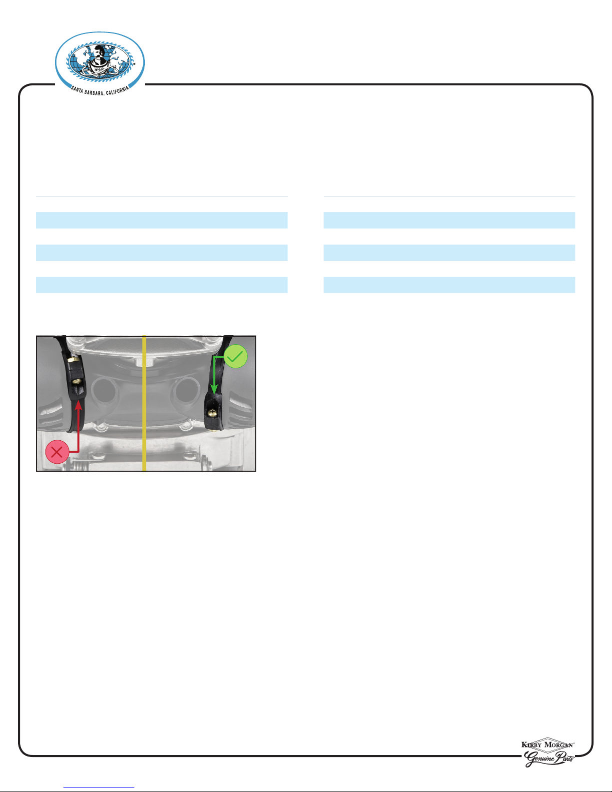
Rotating the clamps will allow more clearance when
installing the regulator shroud, making the installation easier.
• Torque Wrench
• , ⅞ and 1 inch Open End Attachments
• , ⅞ and 1 inch Open Ended Wrench
• ¼ inch Flat Blade Screwdriver
• Small Phillips Screwdriver
• Small Cutting Pliers
• Dow Corning® Molykote® 111 Lubricant or Equivalent
© ⅯⅯⅩⅧ Kirby Morgan Dive Systems, Inc. All Rights Reserved Document # 180117001 Page 1 of 8
Kirby Morgan Dive Systems, Inc.
1430 Jason Way Santa Maria, California 93455
Phone: 805/928-7772 Fax: 805/928-0342
www.KirbyMorgan.com email: kmdsi@KirbyMorgan.com
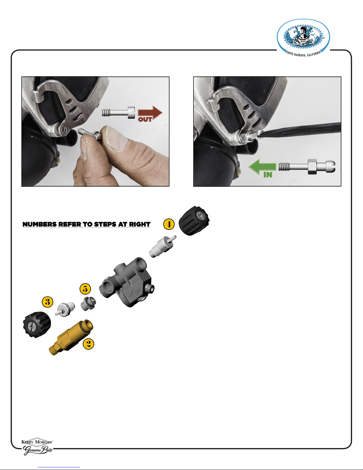
1) Remove and replace the lower two screws with the bishop pins.
®
O
M
R
Y
B
R
I
K
D
I
V
E
S
G
A
N
.
c
n
I
,
S
Y
M
S
E
T
Side Block
2) Remove the one way valve assembly
from the side block.
3) Remove the emergency valve control
knob and all parts down to the seat assembly.
4) Remove the steady ow control knob
and all parts down to the seat assembly.
5) Remove the bailout hose tting.
6) Remove the bent tube assembly. Refer to “1.3.1 Removal of the Bent Tube Assembly” on page BNT-4 in the
KMDSI modular manual.
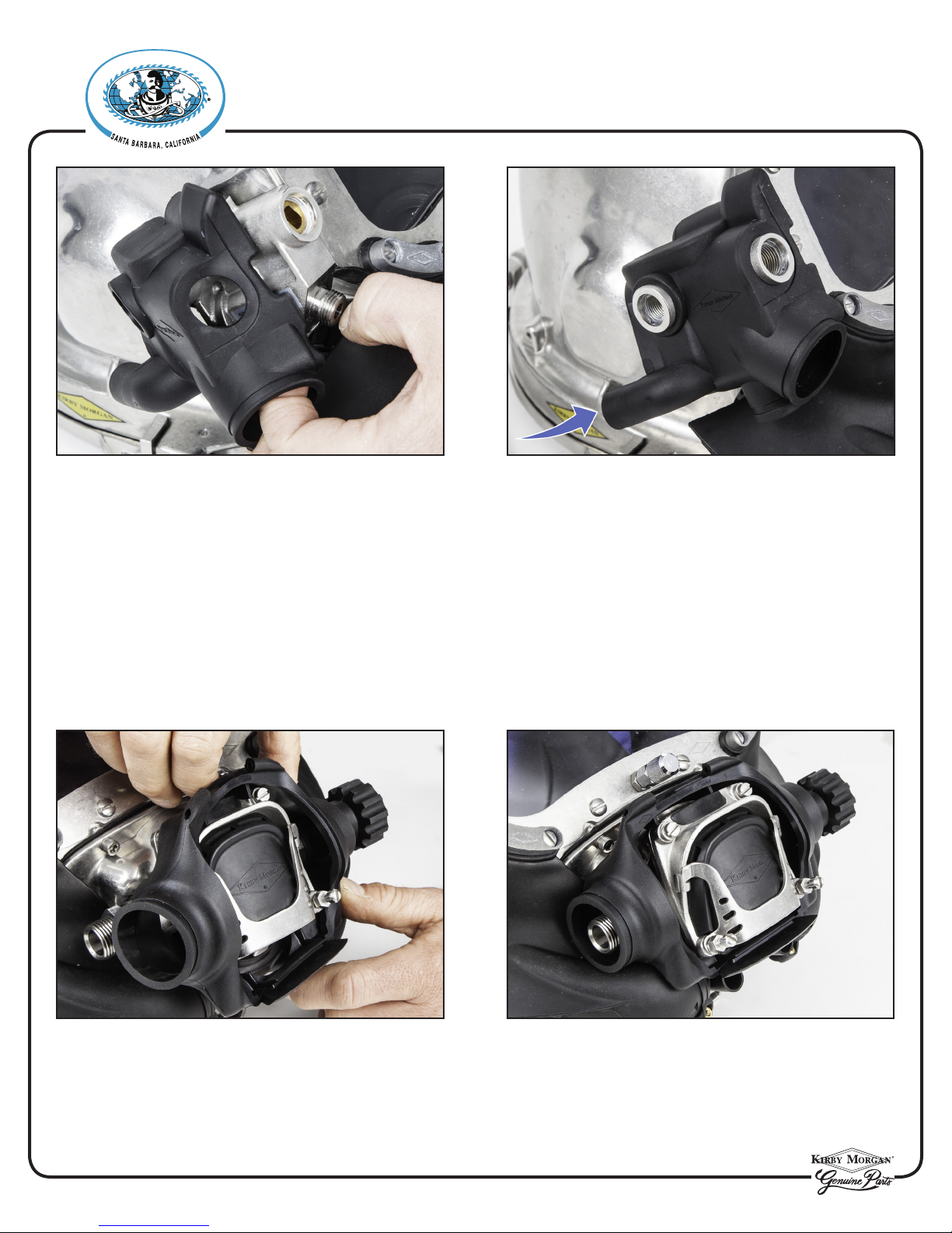
7) Install the side block shroud starting at the bailout end.
Fit the shroud onto the block while progressing towards the front of the block. Make certain the shroud is
positioned properly. The t should be snug and everything should align.
© ⅯⅯⅩⅧ Kirby Morgan Dive Systems, Inc. All Rights Reserved Document # 180117001 Page 2 of 8
O
M
R
Y
B
R
I
K
G
A
N
Kirby Morgan Dive Systems, Inc.
1430 Jason Way Santa Maria, California 93455
Phone: 805/928-7772 Fax: 805/928-0342
D
I
V
E
S
Y
S
E
T
8) Reinstall all of the side block parts that were removed except the bent tube assembly.
.
c
n
I
,
S
M
www.KirbyMorgan.com email: kmdsi@KirbyMorgan.com
®
Regulator Shroud
9) Lightly lubricate the opening of the regulator shroud, 455 P/N 510-723, where the adjustment knob of
the regulator will pass through.
Notice the opening is surrounded by many ne slices to allow the shroud in that area, to eas ily spread over
the large end of the adjustment knob.
10) Starting at the adjustment knob end of the regulator, slip the regulator shroud over the adjustment
knob.
© ⅯⅯⅩⅧ Kirby Morgan Dive Systems, Inc. All Rights Reserved Document # 180117001 Page 3 of 8
 Loading...