

Kirby Morgan 77 User Manual
Kirby Morgan 77
WARNING
WARNING
Chapter 3.0
Operating Instructions
This manual is our effort to explain the operation, maintenance and use of the Kirby Morgan helmet. We do not herein make any effort to teach the principles of diving. It is our assumption the
reader is a qualified diver. We highly recommend that all divers should train, under controlled
conditions, in the use of any model of commercial diving helmet that they have not previously
used or trained in, prior to use on the job.
3.1 Introduction
This section provides advice on how to use your Kirby
Morgan helmet. The use of these diving helmets will
vary with the type of work and environmental conditions. The basic procedures of donning and removing
these helmets will be similar for every job.
A proper training program in a calm, clear body of
water should be undertaken. If the diver has not used
a particular Kirby Morgan helmet before, he must not
dive with the helmet without proper training.
However, divers that are familiar and trained in the
use of previous Kirby Morgan masks; i.e., KMB 8,
9, 10, 18, 28, the Navy MK. 1 Mask, Navy MK. 21
helmet, or the Navy MK. 22 mask or the SuperLite
helmets, will find that all Kirby Morgan diving helmets and masks have the breathing system controls
located in the same position. The operation of this
helmet will also be similar. The diver must be tended
at the surface at all times by a trained, qualified commercial diving tender.
The umbilical is the diver’s lifeline to the diving
control station.
Kirby Morgan diving helmets are not intended for use with a self contained gas
supply (scuba). There is no provision
for surface swimming once the scuba
air supply is depleted. This could lead
to suffocation or drowning, which could
be fatal.
3.2 Design Purpose
All Kirby Morgan diving helmets are designed for
use with an umbilical.
The umbilical is usually composed of at least a gas or
air supply hose and communication wire, assembled
with waterproof tape (and in some umbilicals wound
similar to strands in a rope) to form a single unit.
Some umbilicals also include a hose for hot water, a
pneumofathometer hose, and a strength member, such
as a cable or strong line.
It is strongly recommended that the air/gas umbilical
be married to a strength member in a manner that
allows the strength member to receive the strain.
This will help reduce the possibility of umbilical and
umbilical fitting fatigue and possible failure.
© Copyright 1970-2008 Kirby Morgan Dive Systems, Inc. All rights reserved. Document #080626002
The diver must be tended at the surface at all times by a
trained, qualified commercial diving tender.
41

Kirby Morgan 77
WARNING
WARNING
The diver must be tended at the surface at all times
by a trained, qualified commercial diving tender.
Never dive without a qualified tender holding your
diving hose.
The diving control station can be at the surface, in
a diving bell, or in a submerged habitat. The diving
control station is the center of the air/gas supply, communications with the diver, and diving procedures.
The station can be as simple as a tender with a set of
“phones” (communication amplifier), or as complex
as a control van in the midst of a saturation system.
All diving always involves the risk of
decompression sickness. Omitted decompression due to loss of gas supply or
other accidents can cause serious injury
or death. The use of the Kirby Morgan
helmets or masks cannot prevent this
type of injury.
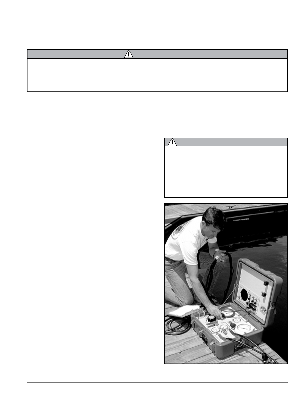
KMDSI manufactures a complete Air Control System,
the KMACS 5™ with integrated communications
and pneumofathometer. This portable system can be
operated on either a high pressure air supply or on a
low pressure compr essor. The Ai r Control System ha s
a specially designed high pressure regulator that reduces high pressure air and provides an adequate flow
to support divers to a depth of 130 fsw (40 msw)
The helmet demand regulator and side block assemblies have been designed to operate with a supply
pressure from 130 p.s.i.g. (8.8 bar) to 225 p.s.i.g.
(16 bar) over ambient pressure. This wide operating
range allows flexibility when using various gas supply systems.
For maximum breathing performance it is desirable
to maintain an over bottom supply pressure in accordance with the low-pressure and high-pressure
supply tables found in Chapter 2 of this manual. With
the many different gas supply console configurations
in use, it is important to ensure that the gas supply
system used, is capable of supplying the helmet with
the necessary pressure and flow of gas to allow the
diver to work safely and efficiently.
There are also detailed checklists for the set-up and
maintenance of your helmet on the Dive Lab web site
at www.divelab.com.
3.3 First Use of Your Kirby Morgan
Diving Helmet
When you first receive your Kirby Morgan diving
helmet, carefully unpack it and examine it for any
damage that may have occurred during shipment.
Use the inspection sheet provided to ensure that no
damage has occurred. The purchaser must contact
the freight carrier and/or the KMDSI dealer if the
helmet has been damaged in shipment.
Early production of the REX 77 helmet had a much
different surface finish than what is found on current
production runs.
Earlier helmets shells and components were finished
using a combination of glass and Stainless Steel
beads; this gave a dull or flat looking surface finish.
Later shipments have a surface finish with a much
smoother and almost shiny appearance. Although the
parts are not shiny, the surface finish is very smooth.
A Scotch-Brite
pad will remove buildup of unwanted surface deposits on both older, and newer REX 77 helmets. It can
also be used to give the main helmet components on
newer helmets, a satin (brushed ) finish.
®
, (or similar non metallic), scouring
High pressure supply regulators and associated piping systems for surface supplied diving with Kirby Morgan helmets
and masks must be capable of delivering
a minimum of 3.2 acfm to the diver at
depth. Only systems that can deliver the
required gas flow should be used.
42
© Copyright 1970-2008 Kirby Morgan Dive Systems, Inc. All rights reserved. Document #080626002
Be sure to complete the enclosed warranty card
and return it to KMDSI immediately. No warranty
claims will be honored without a correctly completed warranty card on file at KMDSI.
WARNING
3.4 Initial Adjustments to
WARNING
O-ring
Split
Ring
Neck
dam
Stepped
Ring
Pull
Strap
Screw
Your Helmet
Before using the helmet for the first time, it must be
checked and adjusted for proper fit. There are several
adjustments that must be made to provide a more
comfortable fit when wearing the helmet.
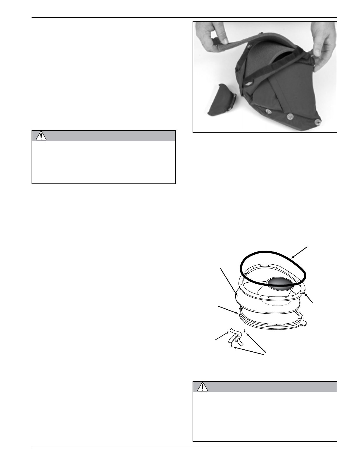
3.4.1 Head Cushion
The fit of the helmet is primarily determined by the
layers of open cell foam that fill the head cushion
bag.
The center top/rear foam is very dense to reduce
KMDSI must have your current address to
ensure that you receive all safety notices
and other important information concerning the helmet. Please notify KMDSI of
any change of address.
compression and spring-back. This reduces the tendency of the helmet to ride up when underwater. Do
not replace this rigid foam with a soft foam. A softer
foam is used on the sides and around the bottom of
the head cushion.
Kirby Morgan 77
The head cushion should be adjusted for best fit.
dam opening so that the two “edges” of the neck
dam are parallel. The neck dam must be under slight
tension but must not be stretched beyond its normal
length. Trim the neck dam with the largest, sharpest
scissors available, in order to make as few cuts as
possible. There must be no jagged edges on the neck
dam or it may tear.
Trim only 1/4 inch off the neck dam at a time. When
you are done, the neck dam must be just tight enough
The diver’s head can be moved forward into the oral
nasal mask by adding layers of additional foam at the
rear of the head cushion. Do not add to much foam to
the rear of the head cushion, as this may position the
diver’s chin too far into the oral/nasal mask and create
an uncomfortable fit. The diver’s head can be moved
up or down in the helmet by decreasing or increasing
the foam pads at the top of the head cushion.
Usually, a diver with a small head will use all the foam
that comes with a new hat. A diver with a larger head
will need to remove a layer of foam in the center top
and back of the head cushion. The foam may be cut
with scissors to provide a better fit, or more foam can
be added to give a tighter fit.
The chin cushion can also be adjusted if necessary.
3.4.2 Trimming the Neck Dam
If your helmet is new, or any time you replace the
neck dam, it must be adjusted to fit you. New neck
dams are cone shaped and will probably be too tight
if not properly trimmed.
The neck dam must be trimmed to fit your neck. To
trim the neck dam, have your tender hold the neck
© Copyright 1970-2008 Kirby Morgan Dive Systems, Inc. All rights reserved. Document #080626002
Neck Dam components.
Never dive with a neck dam that is too
tight. A neck dam that is too tight could
cause the diver to pass out due to pressure on the carotid artery in the neck.
This could lead to severe personal injury
or death.
43
Kirby Morgan 77
CAUTION
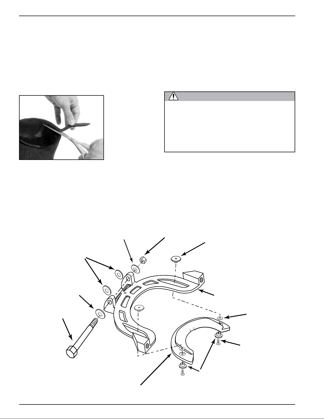
Hinge bolt
Nut
Locking collar
Neck pad
Adjustment nut
Washer
Screw
Washer
T-washer
Teflon
Washer
Washer
so that it does not leak. This may feel a bit snug out of
the water, but should be comfortable underwater.
If you have a neoprene neck dam, it may also need to
be stretched for it to fit properly. Trim the neck dam
until it is still snug, then stretch it by sliding it over
a scuba tank and allowing it to sit overnight. If you
still cannot get the proper fit by stretching the neck
dam, it must be trimmed further. Do not trim more
than 1/4 inch at a time.
Trimming the
neck dam.
As the neoprene
neck dam ages, it will become looser, due to a natural
breakdown of the cells. This is particularly true if
the helmet is locked in and out of a bell or saturation
system. As the neck dam becomes worn it will need
replacement to ensure that it seals properly.
3.4.3 Adjusting the Neck Pad
Another component that controls the fit of the Kirby
Morgan helmet is the adjustable neck pad. The neck
pad, which is mounted on the locking collar, slides
back and forth along the locking collar body for
adjustment to fit different divers. Two screws and
adjustment nuts lock the neck pad plate to the locking
collar. Loosening these screws from the mount nuts
allows the neck pad to be adjusted.
Avoid trimming neoprene neck dams too
much. Neoprene neck dams will loosen
over time as they are used and the cells of
the foam neoprene break down. If you trim
the neck dam too much it will be too loose
and will leak. Trim the neck dam until it is
snug, then stretch it before use.
The following procedure requires a diver and tender.
You do not need to have the air on to the helmet if
you do not use the neck dam ring assembly. If the
neck dam assembly is used, the diver must have air
to the helmet to breathe.
With the helmet face down on a suitable surface, pull
and turn each of the sealed pull pins until they are
locked open. Swing the locking collar/neck pad as-
Locking Collar components.
44
© Copyright 1970-2008 Kirby Morgan Dive Systems, Inc. All rights reserved. Document #080626002

Kirby Morgan 77
WARNING
WARNING
sembly out away from the base of the helmet. Slightly
loosen the screws until the neck pad can slide back
and forth. Be sure each of the head cushion snaps
are attached to their corresponding fitting inside the
helmet.
Pick up the helmet and pull the nose block device
knob out fully. Position the helmet on your head so
the oral nasal is in the proper position on your face,
covering your nose and mouth. Turn the sealed pull
pins to the locking position with the ridge on the pins
engaging the notch in the sleeve and the pins fully
retracted.
Tilt your head forward so the lock i ng colla r/neck pad
assembly may be swung forward and locked up into
its closed position. The sealed pull pins must snap
into place on the locking collar.
Lift your head back up and slide the neck pad forward
until it is snug but comfortable. Mark the position of
the neck pad on the locking collar using an indelible
marker. Pull the sealed pull pins out to their unlocked
position and let the locking collar open.
3.5.1 Pre-Dive Visual Inspection
Visually inspect the exterior and interior of the helmet.
1) Inspect the regulator cover for any damage. The
purge button must work.
2) The neck dam must not be torn or punctured, and
properly trimmed to fit.
There must be no holes in the neck dam.
If there are any holes in the neck dam the
helmet could leak or flood. In addition,
the demand regulator will not operate
properly. Drowning could result.
3) Inspect the O-ring on the neck dam ring assembly. The O-ring must be in place, undamaged, and
lubricated.
Remove the helmet. Position the neck pad plate on the
locking collar at the marked position and tighten the
screws on each side. After the adjustment screws are
tightened, don the helmet again, tilt your head forward
and lock the locking collar/neck pad assembly. Move
your head in various positions to make sure the pad
is adjusted for comfort.
The helmet is now adjusted for your head. It should
need no further adjustment unless another diver uses
the helmet.
3.5 Pre Dress-In Procedure
Before dressing in for a dive, inspection of the helmet
systems must be made to be sure it is in proper working order. This must be done well in advance of the
dive so any problems can be fixed without delaying
the dive. The following steps are part of the recommended daily maintenance.
The O-ring on the neck dam ring assembly on the Kirby Morgan helmet must be
in place and in good condition. It must
be properly lubricated for smooth operation. Without a proper functioning O-ring
the helmet will leak and possibly flood.
Drowning could result.
4) Inspect the bent tube that supplies breathing gas
to the regulator. There must be no dents or kinks in
the assembly.
5) Inspect the face port. It must be in good condition.
6) Be sure the communications wires are hooked up
and tested.
7) Inspect the oral/nasal mask. Make sure it is on
the regulator mount nut properly and the valve is
installed properly.
8) Inspect the sealed pull pin on each side of the helmet. They must engage and disengage properly.
9) Make sure the head cushion and chin cushion are
properly fastened inside the helmet. The chin strap
should be open as wide as possible.
© Copyright 1970-2008 Kirby Morgan Dive Systems, Inc. All rights reserved. Document #080626002
45
Kirby Morgan 77
WARNING
10) Check the screws on the port retainer . They must
be adjusted to the proper torque setting specifications
noted in Appendix 1 of this manual. Binder head
screws are used in this application for their self locking characteristics.
All parts on Kirby Morgan diving helmets
must be adjusted to their proper torque
specifications. See Appendix 1 for a
complete listing of torque specifications
for each part. Failure to adjust parts to
the recommended specifications could
lead to helmet failure and accidents. This
could be fatal.
3.6 Preparing the Helmet for Diving
3.6.1 Clean Face Port
Thoroughly clean the face port with a soft cloth and
a mild liquid soap solution. DO NOT USE ANY
AEROSOL SPRAYS ON THE POLYCARBONATE
PORT!
3.6.2 Check Moving Parts
Check all moving parts, such as the regulator adjustment knob, the defogger control knob, emergency
(EGS) knob, and the nose block device knob and
all locking collar parts to ensure smooth and proper
operation.
3.6.3 Check Communications
Check the communications system for proper operation. Put the helmet on and talk to an assistant on the
amplifier. If you are by yourself, with the helmet off
take the helmet near the amplifier and tap on each
earphone and the microphone, listening to the taps
on the amplifier/speaker. Talk into the amplifier/
speaker feeling the vibration on each earphone and
the microphone with your fingertips. Check the fit
and tightness of the comm module mount nut.
3.6.4 One Way Valve Check
The one way valve must be tested daily, prior to
commencement of diving operations.
1) Prior to attaching (or pressuring up) the umbilical,
close the emergency valve knob, attach and pressure
up the emergency hose. Shut off the defogger control
knob and screw in the adjustment knob on the regulator all the way.
2) With the emergency hose pressurized, turn on the
emergency valve knob. If any gas escapes out the end
of the adapter, the one way valve is faulty and must
be rebuilt or replaced. A one way valve repair kit is
available to rebuild these valves (Part # 525-330).
You can test the one way valve by connecting the bailout bottle to the emergency valve and pressurizing the
sideblock. There must be no gas leakage through the one way valve.
46
© Copyright 1970-2008 Kirby Morgan Dive Systems, Inc. All rights reserved. Document #080626002
WARNING
WARNING
The one way valve must be tested daily,
WARNING
prior to commencement of diving operations. Failure of the one way valve could
cause serious injury or death.
Kirby Morgan 77
3.7 Emergency Gas System (EGS)
If the diver’s main gas supply fails, the diver must
have another source of gas that will enable him to
return to the dive station or to a point where a normal gas supply can be reestablished. For this reason,
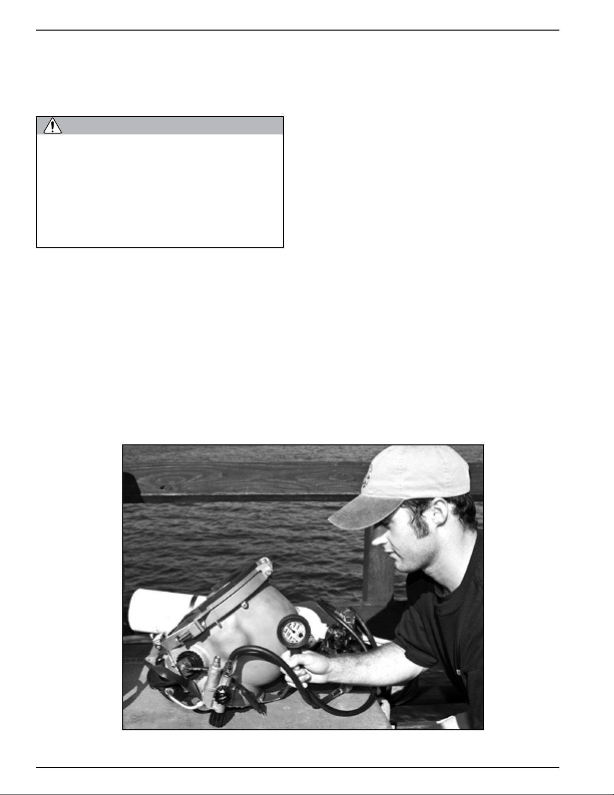
an emergency gas supply (bailout) cylinder must be
used on all dives. The bailout cylinder is normally
worn on the back using a combination backpack and
lifting harness.
Do not dive without a diver worn Emergency Gas System. If the main gas supply
is lost, you will have nothing to breathe
and may drown.
You can also test the one way valve by attempting
to suck air through the valve. The emergency valve
must be open for this test to work properly. If you
are able to suck any air through the valve it is not
working properly.
Never dive if the one way valve is not operating properly. If the hose or breathing
gas/air fitting breaks near the surface a
serious injury could result to the diver’s
lungs and/or eyes. In extreme cases this
could be fatal. The one way valve must be
tested daily prior to the commencement
of diving operations.
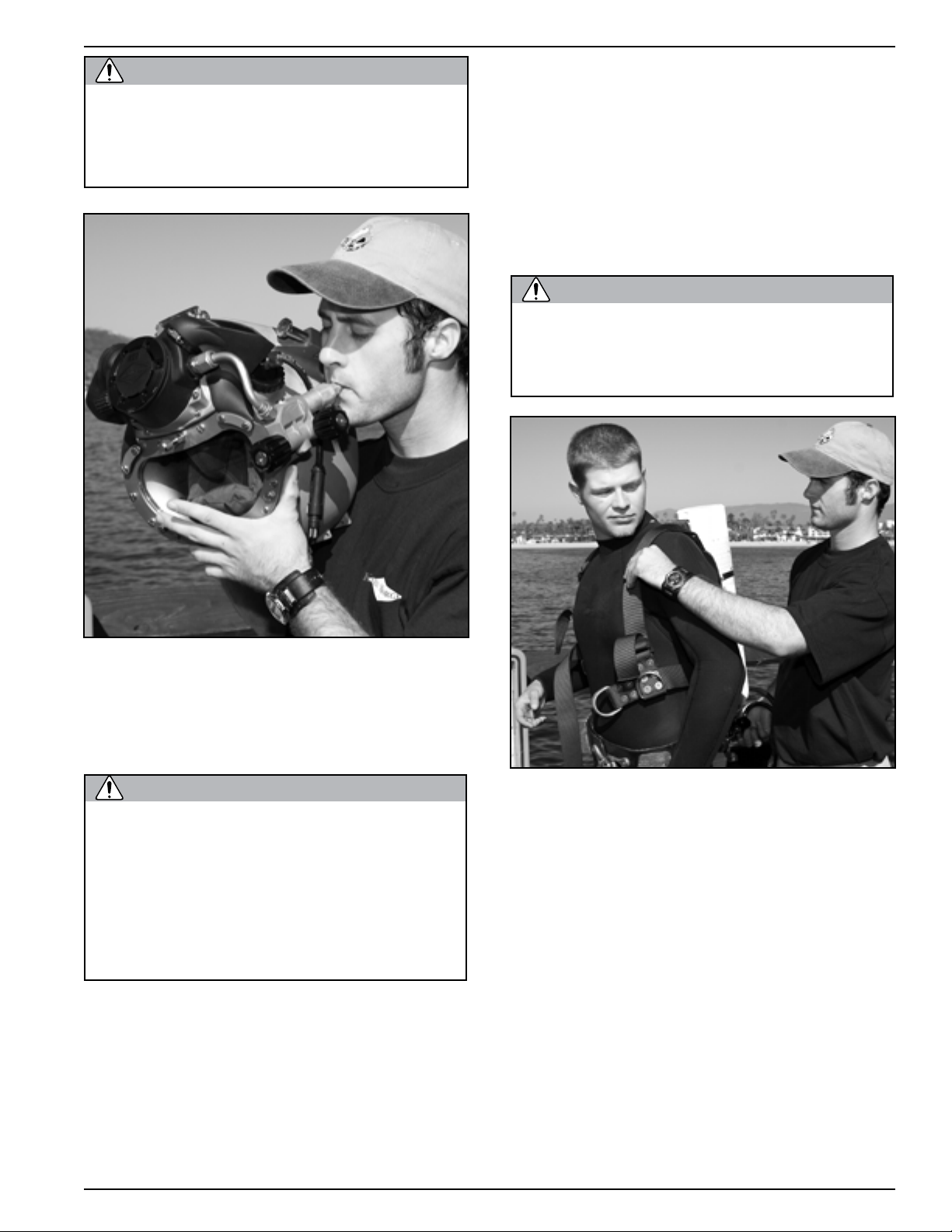
Diver donning a complete bail-out system.
Most commercial divers wear a harness (separate
from the weight belt) that is used for several purposes. The harness is fitted with large metal rings
(usually brass or stainless steel). The umbilical is
hooked into one of these rings to keep any strain off
the helmet. In addition, the rings on the harness are
used to hang tools and other equipment. Usually the
harness is also designed to provide a means of lifting
an unconscious diver from the water. This harness is
the best method of securing the emergency breathing
gas to the diver.
© Copyright 1970-2008 Kirby Morgan Dive Systems, Inc. All rights reserved. Document #080626002
47
 Loading...